Article Contents:
- Five furniture tasks that require different profiles
- Where the decorative ends and the structural begins
- The free space around the frame also matters
- Do you need to rout the rebate yourself
- When a decorative profile should not cover the seam
- The gap between fronts is not equal to the free space for decor
- How to leave a comfortable grip zone
- Three verticals instead of one wide one
- When a butt joint is needed instead of a miter joint
- Another case where linear meters are misleading
- Carved moulding requires a separate ornament alignment map
- Can the same item code be used for both the furniture front and the edge?
- If the catalog lists a profile size of 25 × 12 mm, can the profile be installed on a 12 mm thick panel?
- What should I do if the suitable profile is only available in a length that is too short for the cabinet?
- Do I need to replace the entire frame if one damaged slat is being replaced?
- Can solid oak be replaced with MDF if everything will be covered with enamel?
- How can I be sure that the ordered slat will not change the external dimensions of the furniture?
- Can I first buy only a short sample?
- What determines the cost of a finished decorative assembly?
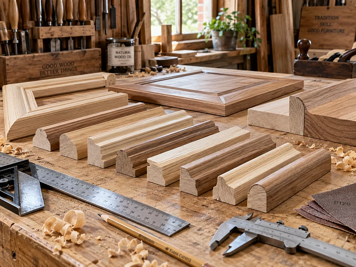
On a facade drawing, two decorative strips 17 mm wide may look identical. But place them against a finished door, and the difference becomes obvious. One protrudes 10 mm above the surface, the other has a cross-section 12 mm high. The first does not interfere with the hand near the handle, the second ends up too close to the grip zone. And if the strip needs to be installed not on a flat surface but on an edge or a transition between panels, both may turn out to be unsuitable: they simply do not have the required shape on the back side.
That is why a decorative wooden profile is chosen based on the design of the furniture assembly, and only then by the pattern, wood species, and photograph. For an overlay frame, the visible width and precision of the corners matter. For an edge, the cross-sectional geometry, the way the end is closed, and the position of the mounting surface matter. For a transition between two parts, the ability to cover the seam without wobbling, gaps, or interference with moving facades matters. A single profile rarely performs all these tasks equally well.
A joinery workshop has a simple way to avoid a mistaken purchase: draw a cross-section of the assembly, mark the actual thicknesses and clearances, compare them with the cross-section of the selected product, and only then calculate the linear meters. If the catalog has no suitable shape, it is more reasonable to change the design of the assembly or manufacture the required profile separately than to try to adapt a random molding.
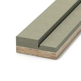
Five furniture tasks that require different profiles
The word "profile" describes the cross-sectional shape of a long part. But a furniture maker has to choose not an abstract geometry, but a specific way of using it. One cabinet needs three different lines: a narrow frame on the door, the termination of the top cornice, and the transition from the side panel to the protruding front panel. Externally, all three elements may be wooden strips, yet they work differently.
| Installation location | What the part must do | The main check before ordering |
|---|---|---|
| Frame on the facade | Outline the contour of the panel or decorative field | Width, projection, miter joint, and distance to the handle |
| Open panel edge | Finish or close the visible end | Panel thickness, back side shape, edge protection |
| Transition between two planes | Hide the seam or make the offset a meaningful line | Height difference, width of support areas, mounting position |
| Vertical cabinet post | Emphasize the post or connect parts of the furniture portal | Length without a joint, axis alignment, adjacency to the cornice |
| Top or bottom termination | Form a cornice or horizontal border | Overhang, end cap, junction angle and support |
| Repeating decorative line | Create rhythm on the facade | Spacing, end margins, section uniformity and fastening |
An overlay molding most often rests on a flat facade surface. An edge profile may require wrapping around an end, a rebate or a special groove. A transition element must align with two bases at once. Therefore, you cannot buy any wooden furniture molding and consider it a ready-made solution for all joints.
В STAVROS wooden trim catalog features moldings, battens, cornices, architraves, corners and other profile products. These are not names that can be freely swapped: the category should be chosen by purpose, and the specific design by the section drawing.




Where the decorative ends and the structural begins
There is another distinction. An overlay profile can cover a seam, but that does not mean it pulls apart separated parts together, reinforces a sagging shelf or replaces a load-bearing joint. Even solid oak does not turn a decorative strip into a structural load-bearing part simply because of the strength of the species. The load must be borne by the joints, base, fasteners and supports provided by the design.
If a gap has formed between the side panel and the front post due to deformation of the cabinet body, first determine and eliminate the cause. Installing a beautiful profile over a joint that continues to move only hides the problem until the next change in geometry.
Our factory also produces:
The cross-section should be examined from the end, not only from the front
The width of the strip helps to imagine how much space it will occupy on the front surface. But this is not enough to understand how it will sit on the furniture. A cross-section has a most protruding point, radii, chamfers, possible recesses, and a flat part with which the piece contacts the base. Sometimes the visible line does not run through the center of the width but is shifted to one side.
To check, make a full-scale cross-section of the furniture assembly. It should show the thickness of the front, the nearest edge, the installation location of the profile, the space in front of the surface, and adjacent elements. Then transfer the contour of the selected profile. Such a simple diagram immediately answers questions that a photograph cannot resolve: whether the decor overhangs the end, whether there is room for its back side, whether the protrusion interferes with the handle, and whether a neat corner can be achieved.
In the product cards of many STAVROS mouldings, dimensions are given as A × C × L. Usually A characterizes the width of the cross-section, C its height or depth, and L the length of the strip. But the direction of measurement and the actual installation projection must be verified against the drawing of the specific item. Dimension C is not a universal promise that the entire profile will protrude from the furniture plane by exactly C millimeters: with a shaped cross-section, part of the height may be accounted for by a different bearing geometry.
| Parameter | What it is for | What cannot be determined from it alone |
|---|---|---|
| A — dimension across the profile | Whether the line fits into the front, shelf, or band | Whether the back side is suitable for the base |
| C — height or depth of the cross-section | How bulky will the design be | Exact overhang after installation without cutting |
| L — product length | Is it possible to get the required cut length | How many planks are needed without a cutting map |
| Cross-section shape | How the profile joins with furniture | Can it be replaced with another product without checking |
| Width of the flat part at the back | Is the mounting surface sufficient | Joint strength without considering the substrate and fastening technology |
Two products with identical A and C can also differ in contour. This is especially noticeable on radiused and shaped profiles: one rises smoothly from the edge, the other forms an almost vertical step. In a frontal shot, both look like thin lines, but side lighting reveals different depth and shadow character.
Get Consultation
A real example: identical 17 mm, but different assemblies
STAVROS has a convenient pair for comparison. Wooden molding MLD-059 has a cross-section of 17 × 10 mm, while MLD-019.1 — 17 × 12 mm. For the beech and oak options, the product cards list a length of 2400 mm; the MDF options have a length of 2600 mm. These values apply specifically to the listed versions and must be confirmed when placing an order.
What changes for the furniture maker? The width of the decorative line remains 17 mm. If the outer frame field is marked out on the facade, both strips can occupy a similar area when viewed from the front. But the cross-section height differs by 2 mm, which means the volume and possible interface with adjacent elements differ. The area near the metal handle, where the hand passes close to the surface, can be sensitive even to such a change. On the adjacent facade, the taller profile will produce a more pronounced side shadow.
However, from the difference between 10 and 12 mm, one cannot draw another false conclusion — that the first molding is always better for a narrow frame and the second for a wide cabinet. You need to see the actual shape of the profile. The height of a single cross-section point describes neither its position nor the nature of the curve. When test-fitting, you compare not only the maximum thickness but also how the strip begins to rise above the facade.
For a wider decorative contour, the catalog offers MLD-057 measuring 25 × 12 mm. A MLD-006.1, size 35 × 21 mm forms an already significantly more pronounced cross-section. Substituting one for the other just because "both are wooden and run along the perimeter" means changing the design geometry.
| Actual product | A × C, mm | Length in beech and oak | What to check on furniture |
|---|---|---|---|
| MLD-059 | 17 × 10 | 2400 мм | Small visible field, shape of the back side, proximity of the handle |
| MLD-019.1 | 17 × 12 | 2400 мм | Additional cross-section height and precision of the joint |
| MLD-057 | 25 × 12 | 2400 мм | Sufficient free field for a wider line |
| MLD-006.1 | 35 × 21 | 2400 мм | Pronounced projection, scale of the facade and junction with the cornice |
This table is an example of engineering reading of the catalog, not a permission to use the listed profiles as a protective edge or a load-bearing connecting element. Such functions will require a separate verification of the cross-section and installation method.
Frame on a furniture facade: it is the working field that must be calculated
On a cabinet door 600 mm wide and 800 mm high, it was decided to make an overlay frame. The outer contour of the frame is inset 50 mm from each edge. Therefore, the outer dimensions of the decorative contour are 500 × 700 mm. If a profile with a visible width of 17 mm is used and placed inward from the specified contour, the inner field according to a simple rectangular scheme will be 466 × 666 mm.
Calculation:
- width of the outer contour: 600 − 2 × 50 = 500 mm;
- height of the outer contour: 800 − 2 × 50 = 700 mm;
- width inside the frame: 500 − 2 × 17 = 466 mm;
- height inside the frame: 700 − 2 × 17 = 666 mm.
The numbers describe only the geometry of the face layout. The actual shape of the inner contour depends on the selected cross-section and on which line the dimension is taken from: along the outer edge, the inner edge, or the profile axis. To avoid mistakes when cutting at 45°, the drawing should indicate the specific measurement base used.
If a 17 mm wide profile is replaced with a 35 mm profile while the outer dimensions remain unchanged, the inner field will shrink to 430 × 630 mm. The difference in width will be 36 mm, and in height also 36 mm. On a facade with a large central handle or a carved overlay, this can change the entire composition. Therefore, a wider profile cannot be approved in isolation from the rest of the decor.
The free space around the frame also matters
A 50 mm outer clearance is not always free installation space. A front panel may have a chamfer, a profiled edge, a hinge cup on the reverse side, a handle fixing, a glass insert, or a panel field. For example, the handle is installed 55 mm from the vertical edge, while a decorative moulding starts at 50 mm. Even when the fixing holes themselves do not intersect, a hand may catch on the protruding line. On a working door, it is not just one fixing point that is checked, but the entire grip path.
For a furniture maker there is another constraint: if the frame covers areas near the moving edge, the door must be tested in all opening positions. A beautiful clearance in the front view does not yet confirm the absence of collision with an adjacent front panel, side panel, or architrave.
How to choose a profile for the open edge of a panel
The end face of a furniture component is a completely different assembly. Let us imagine a panel made of 18 mm thick material: the edge is visible from the side, while the top and bottom are two face surfaces. Is it necessary to cover the entire 18 mm of the end face, soften only the top edge, or run a decorative strip along the edge? The shape of the product depends on this.
An overlay moulding with a width of A = 25 mm is not in itself an edge profile for an 18 mm thick panel. Its visible width may be greater than the thickness of the substrate, but the profile may have a rounded face and a flat reverse seating area designed only for installation on top of a front panel. It will not wrap around the end face in the way a purpose-designed edge component does.
Three different constructions are possible:
- An overlay trim on the face surface. The line is positioned near the edge, but the edge itself is finished separately. This technique is suitable when the task is primarily decorative.
- An end-face overlay. A separate component covers the end face directly, and its thickness and shape are matched to the board. Here the contact area, the end-face pattern, and subsequent corner finishing are essential.
- A profile with a wrap or rebate. A special cut allows the component to extend onto the edge or rest on a step. The seating geometry must be checked before purchase, since the external dimension A is not sufficient.
If you need a profile for a furniture edge, start with the thickness of the substrate, not with the width of the strip you like. Measure the panel at several points, check its straightness, and draw the required seating cut. For solid wood, take into account possible dimensional changes across the grain when humidity fluctuates: a long rigid facing should not be designed in such a way that it prevents the natural movement of the wood.
Do you need to mill the rebate yourself?
Sometimes a suitable face profile has already been found, but the back cutout is insufficient. In that case, the workshop may consider milling its own, provided that a sufficient cross-section remains after milling, the product can be securely fastened, and the manufacturer does not prohibit modification. On a small decorative profile, a cutout of just a few millimetres can noticeably reduce the rigidity of a narrow section or lead to chipping.
In the MLD-059 product page, the manufacturer indicates the possibility of a custom rebate under certain conditions. This is an example of how the back geometry can sometimes be agreed additionally, but the service does not mean that every moulding in the catalogue is already supplied with the required groove. The minimum volume and current conditions must be clarified for the specific article number before calculating the project cost.
The transition between two planes: how to cover the height difference and where to support the profile
The transition joint has a hidden complexity. The profile must look seamless, even though two different parts lie beneath it. This could be a cabinet side panel and an applied face stile, a panel and a frame, a furniture board and an upper decorative band. If the planes are at different heights, the usual flat back of the moulding will not lie against both at the same time.
Let's imagine a 16 mm thick side panel and an adjacent 18 mm thick face part. Their back surfaces are aligned to the same base, so the front planes differ by 2 mm. Visually, this is an almost imperceptible step. But if you apply a moulding with a flat back to both surfaces at once, it will rest on the protruding part and leave a gap above the lower one. Fastening pressure will not correct the geometry: the part may bend, skew, or crack.
A furniture maker has several options, and the choice should be based on the future appearance of the product.
Make the bases in one plane. If the structure is still being designed, the face stile can be recessed, the spacer replaced, or the fastening adjusted. Then a continuous mounting surface will appear under the applied profile. This option is often convenient for repeat production.
Use a profile with a provided cutout. A rebate or step on the back can compensate for the height difference if the position of the seam and the depth of the cutout match exactly. You will need to check not only the 2 mm difference but also the width of each support area.
Leave the transition open as a constructive line. Sometimes it is better to emphasise the step with a thin decorative strip on one plane than to cover it with a massive applied moulding. This is especially useful when the two parts must remain detachable or react differently to moisture.
Make a custom transition piece. If the joint is complex and visible from both sides, a ready-made decorative profile may not be suitable. Custom milling allows you to achieve exactly the fit that the project requires.
When joining, it is essential to note on which side the protrusion is located. The same asymmetrical section may work for a left transition and not work for a right one if it cannot be flipped without altering the pattern.
When the decorative profile should not cover the seam
Not every seam should be hidden. On a dismountable product, access to the fasteners may be needed for repair. On a door near the hinges, free movement is required. On a solid panel fitted with allowance for seasonal dimensional changes, a rigid overlay connecting the panel to the frame can disrupt this principle. In such cases, the correct solution is an open expansion gap or separate finishing of each part.
A profile that covers the seam only visually must not turn a movable joint into a rigid one. The difference is especially significant for solid natural wood: wood changes dimensions differently along and across the grain, so a long glue joint across dissimilar directions can create stress.
Mounting surface: the check that gets skipped on beautiful sketches
On a shaped moulding, the face side may occupy almost the entire width A, but this does not mean that there is an equally wide flat surface behind it. The back side may be narrower, contain a rebate, or have two spaced support zones. Adhesive and mechanical fasteners are selected based on the actual substrate and construction, not on the maximum overall dimension shown on the product card.
Before approving the product, place a short sample against the spot where it will sit and check four things. The part must not rock; there must be no unplanned voids under the supporting part; the fastener must not fall into a thin edge of the section; the face geometry must be preserved after pressing.
Two situations require particular caution.
The first is installing a long profile on an uneven carcass. If the ends and the planes of the base do not form a straight line, the mounting strip may follow the curvature, and the furniture will end up with a wavy line. Trying to force it straight with adhesive does not replace preparing the base.
The second is installation onto an already painted or lacquered surface. In this case, the strength of the joint depends not only on the profile and the adhesive, but also on the adhesion of the coating itself to the substrate. Before serial work, check the compatibility of materials and make a trial assembly using the technology of the finishing system being used.
If mechanical fastening is required, the permissible drilling zone must be determined in advance. A thin moulding with a beautiful convex rib may not have enough wood stock at the spot most convenient for a nail or screw. If necessary, the fastener is placed through a more massive part or the installation method is reconsidered, rather than weakening the thinnest section of the profile.
Profile next to a door, drawer and handle: it is movement that must be checked
Furniture looks motionless only in a photograph. Doors and drawers shift relative to the carcass, and a person brings their hand to them at different angles. Therefore, a decorative profile that does not extend beyond the facade outline in the front view can still interfere with use.
The gap between facades is not equal to the free space for decor
Suppose a design gap of 3 mm is left between two doors. An overlay moulding with a section height of 12 mm is placed on one of them. One cannot automatically conclude that the profile is unsuitable simply because 12 is greater than 3: its protrusion faces the room, and not necessarily across the gap. But one also cannot consider the assembly safe based on the fact that the strip lies on the front plane. Everything depends on its position relative to the edge and the opening trajectory.
If the profile is located far from the rebate and does not cross neighbouring elements during movement, its height alone may not be an obstacle. But if it reaches the edge of the door or wraps onto the end, the situation changes. When the door turns, the most protruding point follows a different trajectory, and it is precisely this that must be checked in the assembled furniture.
On a pull-out drawer, a similar problem arises near an adjacent overlay frame. The upper and lower decorative lines may be located on opposite sides of the horizontal gap. Check not only the closed position, but also the first millimetres of drawer movement: the protrusions must not catch on each other or on the carcass.
How to leave a comfortable grip zone
The position of the handle must be included in the drawing before choosing the profile. Take into account the thickness of its base, its projection, the position of the mounting holes and the place where the fingers go. If the handle is located in the middle of a tall facade, a vertical decorative profile running alongside it may interfere with the grip even without physical contact with the metal.
Example: on a flat projection, 15 mm remains between the handle and the molding. The number looks sufficient until the actual width of the handle body and the three-dimensional rib of the profile are taken into account. In this case, measure the minimum distance between their most protruding parts and test the real hand on a prototype facade. There is no universal gap suitable for all handles here.
Sometimes it is more convenient to interrupt the decorative line, create a smooth area for the hardware, or relocate the handle. This can look more cohesive than trying to run the profile through a spot that is constantly touched.
Vertical profile for a wardrobe and furniture portal
A vertical decorative line emphasizes the height of the wardrobe, divides the facades, or connects the lower part of the furniture with the upper cornice. But a long element brings a challenge that is barely noticeable on a small chest of drawers: the available length of the commercial strip.
If the height of the decorative vertical is 2750 mm, and the selected profile version has a length of 2400 mm, it is impossible to obtain a single continuous piece from one strip. This will require changing the design, finding another product with a suitable length, or planning a joint. The weakest scenario is discovering the missing 350 mm after painting the first parts.
The joint location can be tied to a horizontal band, a decorative crossbar, or another element of the composition. Then the joint will no longer seem accidental. However, the connection must not fall into an area where the strength of the assembly depends on the profile, and the fastening method for both segments must be provided separately. For a long visible line on a single plane, mismatched relief, color difference, and a micro-step at the joint are especially noticeable.
One alternative is to deliberately divide the tall vertical into two sections, tying them to a real division of the wardrobe. Another solution is to change the position of the cornice or lower band so that the length of each visible segment matches the available sizes. Changing furniture solely for decoration is not always rational, but at the design stage it is sometimes enough to move the decorative horizontal by a few centimeters.
Three verticals instead of one wide one
Sometimes a designer tries to replace one wide profile with three narrow strips installed side by side. Visually they create a similar band, but additional seams and fastening areas appear. In side light, each strip casts its own shadow. This is already a different composition, not a direct substitute for a wide molding. This technique can be used deliberately, but first it is useful to do a full-size trial fit on a vertical panel.
If rhythmic repetition is specifically required, it is more logical to look for Decorative wooden lamination. If a single continuous transition or an expressive line is needed, the solution is usually determined by the cross-section of an individual profile, not by the number of identical strips.
Horizontal profile on a chest of drawers: the line must account for the drawers
For a chest of drawers, there is a choice between two logics. You can set a single horizontal line running across the entire width of the carcass and visually linking the drawers. Or you can create an independent decorative line on each front. In the first case, the carcass and its horizontal bands serve as the base. In the second, the geometry of the individual pull-out components does.
On a chest of drawers with three drawers of different heights, a common line may end up too close to the handle of one drawer and too far from the handle of another. This is not a reason to mechanically move the profile up and down: that would lose the original horizontal. You need to decide what matters more for the project — a continuous band or an identical composition for each drawer.
If the profile is located on a carcass rail, it can be planned as a continuous line that does not cross the moving fronts. If, however, the overlay is on the pull-out front itself, its length and end terminations are tied to the width of that front. Trying to make a physically continuous profile across the gaps between different moving components is unacceptable.
Also check the ends. When a profile ends at the side panel, it may leave the full shape of its cross-section visible. Such an open end sometimes looks neat, especially on a simple geometric profile. On a complex molding, the end may look cut off. In that case, a return to the plane, an end cap, or another meaningful termination is designed. You cannot leave the decision about the ends until installation: they determine the length of the segment and whether it can be manufactured.
The junction of a vertical profile with a cornice and a horizontal band
The most complex section of a decorative portal is usually not in the middle of a long strip, but where the vertical meets the upper horizontal. On an individual front, both elements may look good. But if one protrudes by 12 mm and the other by 21 mm, a step will appear at the intersection point. It can be made intentional, but you need to determine in advance which profile overlaps the other, where the relief ends, and what is visible from the side.
There are three structural schemes.
Butt joint. The vertical component ends beneath the horizontal one. This is convenient when the band should visually run continuously. The end height and the position of the end must be chosen precisely, otherwise a gap or skew will appear.
Mitered intersection. Profiles are joined at a specified angle. This works only if their cross-sections allow a meaningful mating contour. For different profiles, an equal 45° cut alone does not solve the problem of differing reliefs.
Transition via an intermediate element. A separate block, capital, or decorative insert is placed between the vertical and the cornice. Such a joint can conceal a mismatch of cross-sections and express a constructive division. But additional details must be coordinated in scale, not taken solely to mask an error.
At the design stage, it is useful to depict this joint in three views: front, side, and section. A simple frontal sketch almost never shows a full mating of the relief.
Miter at 45°: why the correct angle still does not guarantee a precise joint
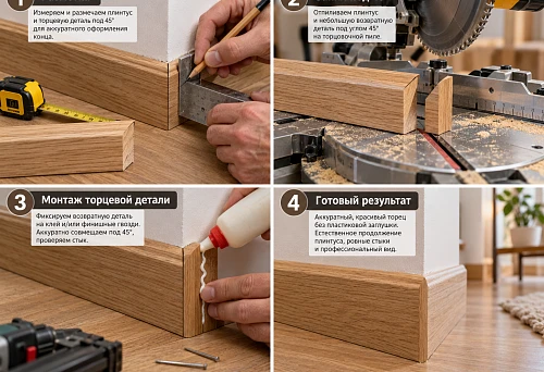
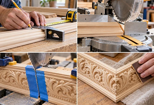
On a rectangular frame made of the same profile, two 45° cuts should form a 90° angle. But a straight cut line is only one condition. If the strip has rotated around its longitudinal axis, the back face rests unevenly, or the end is not made strictly perpendicular to the base surface, a step will appear on the front side. It is especially noticeable on a rounded edge: light highlights even a slight displacement of the arc.
Before cutting, establish the baseline. For a frame, it is more convenient to designate where the outer edge of each segment runs and what the long end of the miter joint will be. If the craftsman measures one strip along the outer side and another along the profile axis, four correctly cut angles will not assemble into a rectangle of the specified size. The error lies in the measuring method, not necessarily in the machine.
First, cut two short test pieces of the same article, assemble the angle on a flat surface, and check that the relief matches. Then close a small test rectangle. At this stage, skews, accumulated error, and differences in the actual shape after finishing are clearly visible.
You cannot require two 45° miter cuts to join precisely if the angle of the furniture joint itself differs from 90°. Suppose that after assembling the carcass, the measured angle is 91°. For a symmetrical joint of two identical parts, the reference will be cuts of about 45.5° — but only if the profile geometry and its installation direction allow such a method. If the deviation is noticeable, the base should be checked first: perhaps the carcass needs correcting, not the decorative frame.
When a butt joint is needed instead of a miter joint
A butt joint has a practical advantage: it does not try to continue the profile around a turn, but ends one line at another. This is appropriate for the transition of a vertical decorative band to a horizontal cornice, if the horizontal must run without interruption. In such a joint, the end surface of the vertical part is sometimes partially covered by the upper profile.
For a continuous straight line that cannot be made from a single strip, a regular straight butt joint can be very noticeable. Depending on the cross-section, a more suitable joint, placement under a decorative bridge, or a pre-planned division is considered. In any variant, the wood grain, the accuracy of contour alignment, and the method of fixing both ends are checked.
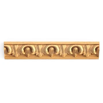
If the profile has a pronounced repeating carved ornament, the choice of joint location becomes even more critical. The same article number does not mean that two randomly cut ends will match in the phase of the pattern. For carved moulding, the segments are matched by the actual motif, not just by length.
End termination of the profile: three options without a randomly chopped line
An open end is often the most noticeable flaw in furniture with moulded decor. In the image, the front line is neat, but from the side, the uncovered end of wood or MDF is visible. Painting can only partially fix this: the color will become more even, but the shape of the termination will not change.
An open termination is acceptable if the profile is sufficiently simple, its end is finished, and it is consistent with the overall geometry. For a rectangular strip, this can be a perfectly normal solution.
The return to the plane is done with a small end segment that changes the direction of the profile and brings the visible line down to the base. This introduces an additional miter joint and a short piece that is difficult to hold during processing. Therefore, the returned end is first made in a trial assembly.
Abutment to a finishing element is chosen when the profile fits under a side post, capital, decorative block, or cornice. In this case, the end should not remain visible, but one cannot assume that it will be covered by the adjacent element until the actual size of the latter has been verified.
For short terminations, not only the availability of material is important, but also the safety of fabrication. A small segment of a complex cross-section cannot be held by hand near the cutting tool to save one workpiece. Appropriate fixtures and safe working techniques are used; if the operation cannot be performed reliably, the part or the assembly itself must be redesigned.
Cutting: total linear meters and number of strips are different calculations
Let's take the described frame with an outer dimension of 500 × 700 mm. Provided that lengths are measured along the long outer sides after cutting, one frame requires two segments of 500 mm and two of 700 mm. Their finished sum is 2400 mm. It would seem that one beech strip 2400 mm long should be enough. But this is impossible: each separating cut consumes material, and additional allowances may be needed for precise end trimming.
If such frames are needed for six identical fronts, the total finished length is:
6 × (2 × 500 + 2 × 700) = 14,400 mm.
Mathematically, this is exactly six strips of 2400 mm. In practice, six will not be enough due to the saw kerfs. The problem is solved with a cutting map that accounts for the specific lengths and the kerf width. For example, with a kerf width of 3 mm used for the calculation, seven strips can be distributed as follows:
| Number of 2400 mm strips | Segments from each strip | Sum of finished lengths | Remainder excluding kerfs |
|---|---|---|---|
| 1 | 700 + 700 + 700 mm | 2100 мм | 300 мм |
| 3 | 700 + 500 + 500 + 500 mm | 2200 мм | 200 mm per strip |
| 3 | 700 + 700 + 500 mm | 1900 мм | 500 mm per strip |
| 7 | A total of 12 pieces of 700 mm and 12 pieces of 500 mm | 14,400 mm | 2400 mm in total |
Even if we conditionally subtract 3 mm for each of the 24 cut-off pieces, that gives 72 mm of kerf loss — the selected combinations remain within the strip lengths. But this is a study layout, not a finished production plan. It does not account for allowances for squaring the ends, rejection of defective sections, the actual geometry of miter cuts, clamping fixture constraints, and grain matching. All of these conditions can increase the purchase quantity.
It is telling that a single frame requires at least two source strips, and when six frames are cut together, the material is used more economically. But it does not follow that it is always better to buy a large volume: the decision depends on the number of items, whether offcuts can be used, and whether reordering is possible.
Another case where linear meterage is misleading
You need to make six long vertical parts of 1300 mm and two horizontal parts of 1000 mm. The total length will be 6 × 1300 + 2 × 1000 = 9800 mm. Dividing by 2400 gives slightly more than four strips, that is, formally a minimum of five.
But you cannot get two 1300 mm parts from one strip: their sum of 2600 mm exceeds the source length even before accounting for the cut. So for six verticals you will need at least six source strips. The two horizontal pieces can be placed on two of them: 1300 + 1000 = 2300 mm, which leaves room for the planned saw cut. The resulting minimum number in this simplified layout is six strips, not five.
For expensive oak moulding, such a difference has monetary significance. It explains why an order should be placed based on a list of finished cut pieces, not just the total length of lines on the drawing.
Carved mouldings require a separate ornament alignment map
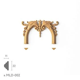
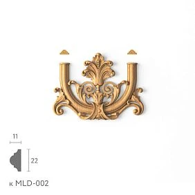
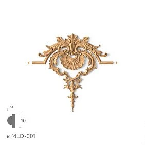
If the profile contains repeating beads, leaves, or a complex frieze, extra length sometimes has to be used so that the beginning and end of the pattern meet at the planned location. An example on a different scale is Wooden Moulding K-097, for which the catalogue lists wide sections of 100 × 16 and 200 × 16 mm with a length of 2000 mm. Such a product cannot be replaced with a narrow frame profile or calculated by the same compositional rules: it has a different scale and a pronounced pattern.
For each section with a repeating motif, determine in advance the permissible end position, the possible loss for alignment, and whether a mirrored arrangement is required. If this cannot be achieved from the catalogue length without a visible break in the motif, it is better to simplify the composition than to formally cover the required linear metres.
Beech, oak, or MDF: the material is chosen for the visible surface and finish
The same section does not mean the same behaviour
Oak is often chosen for profiles where the open texture must match oak fronts and veneered panels. With a clear finish, the character of the pores, the direction of the grain, and the selection of strips within a single product are important. If two lengths with very different patterns are joined on a furniture door, precise sawing will not hide the colour break.
MDF is worth considering for opaque painting when a natural wood texture is not needed and a suitable version is provided by the article itself. With MDF, open ends, cut edges, and the priming technology require special attention. The finishing scheme for solid wood cannot be automatically transferred to MDF, nor should the two materials be considered identical in properties.
| Task | What is worth comparing | Special check |
|---|---|---|
| White or colored enamel on all furniture | Beech and MDF of suitable cross-section | Surface preparation, primer, visibility of joints |
| Clear lacquer on an oak cabinet | Oak profile | Texture, tone, grain direction, matching at the joint |
| Tinted beech furniture | Beech profile | Test tinting on the profile and main material |
| Narrow face frame on a painted facade | Several profiles of the same scale | Width, projection and compliance with the finishing technology |
| Visible edge cladding | Material and profile with the required mounting geometry | End face, fastening, dimensional changes and operation |
STAVROS product cards include wood preparation options "for enamel" and "for tinting". These terms do not denote a finished painted product; when ordering, you should clarify the finish and the planned finishing system. The choice of material and preparation is especially important if the profile is installed on an already finished facade and must visually match it.
How to achieve a neat finish on corners and end faces
On a sample just a few centimetres long, a decorative trim often looks straight. On a full frame, differences between the face, the end face and the mitre cut begin to show. End sections may absorb the finishing product differently; profiled recesses remain less accessible for even sanding and coating; after assembly, it is harder to reach the internal corners.
The decision whether to paint parts before or after installation is made based on the design. If the profile and the facade must have a single continuous enamel surface, it is often more convenient to coordinate the entire assembly as one finishing system. If an open natural texture is required, you have to take separate care over wood selection, the cleanliness of the joint and the quality of the end faces before installation. It cannot be promised that the lacquer alone will hide a mismatch in geometry.
For a profile with visible open ends, the end faces must be treated according to the chosen technology. For a profile with a mitre joint, first check the dry joint, then the appearance after primer or tinting. A preparation error may only become apparent under angled light: a step becomes more noticeable when the coating produces a continuous sheen.
Separately check whether the result changes under lighting from a window or built-in illumination. A profile with the same height C may look visually heavier if its convex part casts a wide shadow. This is a matter of shape and light, not just millimeters.
Profile sample: what can be checked on 100 mm and what cannot
On the STAVROS website there are samples of moulded products 100 mm long. They are suitable for choosing a cross-section, comparing visible width, fitting to the end of furniture, and trial finishing. But a short sample does not confirm the straightness of a future 2400 mm strip, does not show the full character of the wood grain over a long section, and does not replace checking serial cutting.
A sample has a different value: it can be physically placed against a joinery assembly before the entire furniture piece is made. For example, place two 17 mm wide strips next to a handle. Then rotate the facade or change the direction of lighting. If one option creates an unwanted shadow and interferes with grip, this will be discovered before purchasing several dozen linear meters.
For end finishing, check not the front side of the sample, but its reverse geometry. If a rebate is needed, place a template cut from dense cardboard with the required cross-section against it. Such a template may reveal a mismatch already on the drawing, but make the final decision only based on the actual product and a proven installation method.
The approval procedure for the workshop is as follows:
- Determine the installation location: facade, edge, joint, or termination.
- Take the dimensions of the base and all adjacent parts, including gaps.
- Choose several suitable cross-sections from the drawings, not just one molding you like.
- Order samples of the available finishes and attach them to a real assembly.
- Check the shadow, the mounting surface, the possibility of a neat termination, the movement of the door, and access to the handle.
- Make a test joint and a color sample in the chosen material.
- Approve the specific article number, wood variant, cross-section shape, and installation method.
- Only after that, calculate all finish cuts and place the main order.
This sequence is especially useful for custom furniture, where an error is discovered only after the expensive fronts have been manufactured. At an early stage, changing the profile cross-section may cost one new sample. At a late stage, you will have to redo the cutting, holes, or finishing.
When it is better not to install a profile at all
Any additional element has a cost in geometry and maintenance. A shaped wooden profile is not needed just to fill an empty space if there are already a large cornice, bulky handles, carved overlays, and several frames nearby. Too many protruding lines make it harder to clean the furniture and can make working with the fronts inconvenient.
Avoid a specific ready-made profile or revise the assembly if:
- too much of its cross-section has to be removed for fastening;
- the decorative strip covers a necessary expansion or movement gap;
- there is no reliable mounting surface and no other confirmed fastening is provided;
- the new part must perform a load-bearing function for which it is not intended;
- two profiles cannot be joined without a noticeable break in the pattern;
- the required length calls for an unsightly joint right on the most visible part of the product;
- you cannot match the material and color with the existing clear finish.
Sometimes a neatly finished straight edge looks better than a complex molding, and a narrow transition gap is better than trying to hide a step with an unsuitable overlay. Such a solution takes nothing away from the project: it preserves its structural clarity.
How to specify the selected profile in production documentation
For a single custom cabinet, a detailed working drawing and a parts list are sufficient. For a series of several cabinets, it is better to create a separate line for each type of trim. The wording “wooden profile — 15 meters” is too vague. It does not make it clear which exact shape to order, whether a material substitution is acceptable, or where the joints should be made.
| Schedule field | Example entry | What it's for |
|---|---|---|
| Furniture assembly | Upper cabinet section front | Do not confuse the profile with another rail |
| Product | Molding MLD-019.1 | Lock in the specific geometry |
| Size | A = 17 mm, C = 12 mm, L = 2400 mm for solid wood | Do not change the cross-section or length on reorder |
| Material | Beech; preparation option specified in the order | Ensure a consistent finish |
| Finished parts | 2 pieces of 700 mm, 2 of 500 mm per one front | Cut without guesswork |
| Measurement base | Along the outer long end of the miter cut | Avoid size differences on the machine |
| Finishing | Enamel according to the approved sample | Check for a uniform color with the facade |
| Control | Angle, contact plane, protrusion, opening | Prevent defects in assembly |
| Card address | Saved in the project documentation | Repeat the order without searching for similar items |
The workshop assigns project numbers and finish designations independently. For a single furniture model, it is good to store not only the catalog information but also a photograph of the approved assembly, a cross-section of the joint, and a cutting map. If a repeat order is needed several months later, this will help quickly establish exactly what was used.
For a non-standard joint, separately specify the requirements for the rebate, radius, and seating surface. If the manufacturer does not offer such a modification for the selected product, it should not be considered approved by default.
When purchasing for a small series, consider not only the cost of a single commercial strip but also the cost of obtaining the installed part. It consists of the price of the linear stock, delivery, cutting, joint preparation, finishing, installation, and possible losses. A cheaper purchased profile may turn out to be more expensive in use if a lot of manual fitting is required or a significant portion of the strip ends up as offcuts. And vice versa: a small stock of profile material is sometimes economically more sensible than an urgent additional order for the sake of one visible joint.
Where to choose and buy decorative wooden profile for furniture
If you need to buy a decorative wooden profile for a specific joinery assembly, start by choosing the function. For frame lines and furniture fronts, suitable options can be found among wooden moldings and linear trim products. If a figured carved motif is needed, there is a separate carved moulding section. For regular linear layout on fronts, you can consider slats from the catalog.
The queries "buy wooden profile for furniture," "buy furniture profile made of solid wood," and "buy wooden mouldings for furniture" describe different tasks, although they may lead to the same product category. It is more useful for the buyer to search not for the most popular name but for the cross-section that matches their drawing. For reference, compare MLD-059 and MLD-019.1 if a narrow line 17 mm wide is needed, or wider versions if the scale of the furniture requires it. Do not forget the actual shape of the back side.
To clarify the specifications, you can use STAVROS catalogs and drawings. Before painting and installation, it is useful to check the section installation and finishing tips, and also check materials for installation and finishing work. If the purchase is being made by a workshop for a furniture series, the terms can be clarified on the page for manufacturers. Current prices, finishes, and availability are checked when ordering specific items.
The most useful thing to do before buying is to choose two or three similar profiles by actual dimensions, take a sample, place it against the drawing and the real base, and assemble one test joint. After this check, it is already clear whether the strip is suitable for the frame, whether it actually covers the required edge, and whether it can neatly join two furniture planes.
Frequently asked questions when selecting a wooden profile
Can one item code be used both on the facade and on the end of the furniture?
Sometimes this is possible, but only with the appropriate geometry and mounting method. Surface-mounted moulding is designed primarily for working with the face surface. For the end edge, you need to check the base thickness, the shape of the back side, and the required coverage. A matching decorative pattern does not prove that the profile is suitable for the edge.
If the catalog lists a section of 25 × 12 mm, can the profile be installed on a 12 mm thick panel?
The section height should not be equated with the panel thickness. The 12 mm dimension may describe the maximum height of the decorative relief, not the seating depth. A cross-section drawing is needed that shows the position of the mounting surface. Only then can it be determined whether the profile fits the end edge or the face of the panel.
What should be done if the suitable profile is only available in a length that is short for the cabinet?
Check other available versions and lengths. If a single continuous piece is not available, plan the joint location in advance, for example under a horizontal rail. With a continuous sight line, assess how acceptable a straight joint is and whether the wood grain can be matched. In some cases, it is better to change the decorative division of the furniture.
Is it necessary to replace the entire frame if one damaged strip is being replaced?
If the original article number is known and the surviving sides match in section, color, and pattern, a local replacement is possible. When there is no suitable profile with the same section, the new strip may reveal itself as a step at the corners. Then it is sometimes wiser to replace the entire closed contour, especially on painted furniture, where the surface can be refinished as a single whole.
Can oak solid wood be replaced with MDF if everything will be covered with enamel?
A visually suitable MDF part can be an alternative if the specific article number exists in such a material and its use is consistent with the operating conditions of the assembly. However, mechanical properties, edge treatment, fastening, and finishing technology differ. If the profile protects a vulnerable edge, is mounted on a thin base, or is subject to regular impacts, replacing the material requires a separate technical solution.
How can you tell that the ordered strip will not change the external dimensions of the furniture?
It is necessary to check the extreme protrusion of the finished profile after installation. Compare it with the design dimensions of the cabinet and the required clearances relative to walls, adjacent cabinets, and moving doors. Do not limit yourself to the frontal view: additional overhang may only appear from the side.
Can I first buy only a short sample?
Yes, for shape selection STAVROS offers molding samples 100 mm long made from available materials. They help you see the cross-section, make a test stain, and place the element against a furniture part. However, compliance of long strips with project requirements is checked additionally, since a short sample does not show straightness and the characteristics of the entire length.
What determines the cost of a finished decorative assembly?
It depends on the price of the selected profile and material, the length of the cut pieces, cutting losses, the complexity of joints, surface preparation, and installation. For repeat items, the cost of the initial setup is also significant. Therefore, compare options by the finished installed assembly, not only by the price per linear meter.
A wooden profile selected according to the drawing is perceived as part of the furniture structure. Its relief fits precisely into the frame, the edge ends meaningfully, the joint closes without a step, and the door opens freely. It is precisely this correspondence between the cross-section and the furniture assembly that determines the result — regardless of how impressive the strip looked in a separate photo.