Article Contents:
- Why wooden moldings chip when sawed
- Grain direction and the moment the tooth exits
- Oak and beech: different characteristics, one need for control
- Why carved molding is more difficult than a smooth strip
- Miter saw for precise work
- How to choose a blade for a clean crosscut
- Miter box and hand saw
- Additional accessories
- Check the geometry
- Find a stable position on the table
- Mark the workpiece without damaging the face
- Make a test cut
- Checking the tool setup
- Crosscut sequence
- How to support the fibers at the exit
- How to assess a finished end
- Rectangular frame: dimensions first, then the miter
- Keep the profile position consistent
- If the room corner is not square
- What to do about a gap in a finished corner
- Identify the vulnerable areas
- Fastening without damaging the carving
- Test cut and finish cut
- How to remove small burrs
- Oak and beech: sanding without changing the geometry
- Edges for opaque enamel
- Edges for oil, stain and clear lacquer
- MLD-002: a narrow moulding for small frames
- MLD-031: fluted profile
- MLD-032: wave-shaped profile
- K-045: carved "Kosichka" baguette
- Geometric length of the frame
- Cutting plan for 2400 mm long strips
- An example where calculating by linear meters is misleading
- How to reduce waste of expensive carved baguette
- What is the best tool for cutting wooden moldings?
- Can carved molding be cut with a hand saw?
- How to miter a wooden molding at 45 degrees?
- Why does oak molding chip when sawing?
- How do you cut beech baguette correctly?
- Can you use a laminate blade?
- How should a wooden end grain be treated after sawing?
- How do you preserve the ornament when joining carved moulding?
- How much material allowance is needed for cutting?
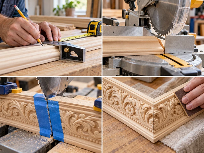
Wooden moulding is often ruined in the final seconds of cutting. Almost the entire kerf comes out straight, but a splinter tears away at the back edge. On a smooth strip this defect can sometimes still be fixed. On carved baguette, the tip of a leaf or the interweaving of the ornament may disappear along with the splinter — restoring it without traces is considerably harder.
To cut wooden moulding without chipping, it is not enough to set the saw to the right angle. The workpiece must rest stably on the table and fence, the disc teeth must suit the wood and a clean crosscut, and the fibres emerging from the kerf must be supported. A complex profile will require a separate jig that keeps it from rocking and being crushed under the clamp.
Products made of oak and beech intended for oil, stain or clear lacquer require especially careful preparation for cutting. Here you cannot count on a wide filler patch disappearing after finishing. The most reliable order of work is to inspect the profile, choose its stable position, check the saw setting on a test cut, make the finish cut, and only then treat the end.
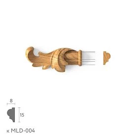
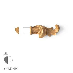
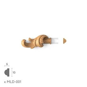
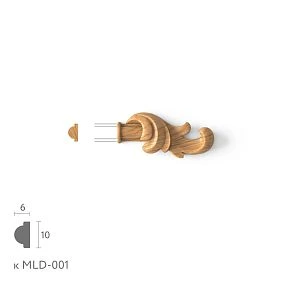
Why wooden mouldings chip when sawed




Grain direction and the point where the tooth exits
Wood consists of fibers oriented predominantly along the trunk. When ripping, the cutting tool moves relative to them differently than when crosscutting. For decorative frames, furniture moldings and wall compositions, a crosscut is more often needed: it crosses the fibers and forms an end-grain surface.
At the start of the cut, the teeth gradually sever the fibers supported by the surrounding wood. At the opposite edge the situation changes: the remaining thin bridge may break off before the tooth severs it. This is how fiber tear-out occurs where the blade exits. If a closely fitting sacrificial stop is positioned behind the workpiece, it supports the edge and reduces the likelihood of damage.
The quality is affected by the exit direction of the teeth of a particular tool. Therefore, no single universal position for the face side — “always up” or “always down” — can be prescribed for any cutting method. The position is checked on a test cut, taking into account the saw design and the installed safety devices.
Chipping is not necessarily caused by excessive wood hardness. It is also caused by a dull blade, incorrect feed, vibration, insufficient support and damage to a thin section before sawing.
Our factory also produces:
Oak and beech: different characteristics, one need for control
Oak has a pronounced texture and a non-uniform structure with large vessels. The transition from a denser section to a less dense one can affect the nature of chipping. Pay especially close attention to strips with a changing grain direction near a knot or another natural feature.
Beech usually has a more uniform texture, but with an unsuitable tool it also produces tear-out and small chips. A well-prepared beech profile does not guarantee a clean cut if it rests on the table on only two protrusions and rocks during work.
It cannot be claimed that oak always saws worse than beech or vice versa. What should be compared is the actual workpieces, the condition of the blade and the result of a test cut. Moisture is important for both materials: an excessively damp or warped strip holds the specified geometry less well.
Get Consultation
Why a carved molding is more difficult than a smooth strip
A standard molding has a cross-section that repeats along its entire length. It can be laid on a suitable supporting edge and secured fairly predictably. Carved trim has leaves, braids or other protruding elements along its face. The surface height constantly changes.
If the clamp lands on a single protruding detail, the entire load falls on it. If there is a void under the strip, part of the profile may sag during cutting. Sometimes a decorative protrusion sits right on the tooth exit line: the thin edge breaks off easily.
That is why two additional conditions are checked for carved products: the support must hold the main body of the workpiece, and the fastening must not crush the ornament. This matters more than trying to increase clamping force.
How to cut wooden moldings and carved trim
A miter saw for precise work
For regular cutting of long wooden trim, a miter saw with a stable table, a rigid stop and reliable locking of the swivel mechanism is convenient. It allows you to repeat straight and angled cuts when making several identical frames.
Check not only that a 45° scale is present, but also the actual accuracy of the settings. Play in the swivel assembly can produce a gap in the finished joint even when the mark on the scale looks correct. For a long profile, side supports in the same plane as the machine table are especially important: a freely overhanging end can pull the workpiece and change the cut line.
Before starting work, read the manual for your specific saw. Do not remove the guard, do not block its movement, and do not use random devices that interfere with the protective mechanisms. When adjusting or changing tooling, disconnect the tool from the power supply.
How to choose a blade for a clean crosscut
For neat cutting, choose a sharp, undamaged saw blade that the manufacturer intended for crosscutting solid wood and that is compatible with the specific saw. The geometry and number of teeth, diameter, arbor hole, kerf thickness and permissible rotation speed all matter.
A blade with aggressive tooth geometry, designed primarily for fast ripping, may leave a rougher edge than tooling intended for clean crosscuts. But the advice to "choose the blade with the maximum number of teeth" is also wrong: you need to consider the diameter, the tool's design, the material, and the tooling manufacturer's instructions.
If you notice burn marks, increased cutting force, or teeth leaving pronounced tear-out even on a proven workpiece, inspect the blade. The cause may be dulling, resin buildup, a damaged tooth, or the wrong choice of tooling.
Miter box and hand saw
A standard miter box is suitable for small volumes of work with compact profiles, provided the workpiece is securely clamped and the guides allow you to maintain the required angle. A hand saw with a suitable fine tooth can deliver a clean result without power tools.
The limitations become apparent on wide, ornate molding and when producing a series of identical parts. A slight deviation of the blade becomes especially noticeable on a long, angled joint surface. If the miter box does not support a shaped strip, you will need a suitable insert or another safe fixture.
Do not try to hold a short part with your fingers near the cut line. If safe clamping cannot be ensured, use other equipment or order pre-cut pieces from a workshop.
Additional accessories
| Tool or accessory | What it is for | What to Check |
|---|---|---|
| Miter saw | Straight and angled cuts, repeatable dimensions | Angle accuracy, condition of the stop and guard |
| Crosscut finishing saw blade | Reduced tear-out, flat end-grain surface | Compatibility with the saw and material |
| Miter box with hand saw | Small profiles and limited volume | Rigidity, guide accuracy, safe clamping |
| Clamp or built-in hold-down | Prevents workpiece shifting | No pressure on fragile threads |
| Sacrificial backer board | Supports fibers at tooth exit | Permissibility of use on this tool |
| Side supports | Support for long linear stock | Height match with the table |
| Square and angle finder | End-face and settings check | Measurement accuracy |
| Soft pads and profiled cradle | Support for complex relief | Stability without deforming the ornament |
Consumable stops and shims may be used only in the configuration and position permitted by the machine manufacturer. They do not replace clamping, standard guards, or a safe zone for hands.
Preparing wooden moldings for sawing
Check the geometry
Place the profile on a flat surface and check that it is straight and free of twisting. If the strip rocks on the intended bearing face, determine the cause before cutting. Do not force a noticeably warped piece down onto the table with excessive pressure: once released, it may change shape and the angle will turn out inaccurate.
Mark any existing chips, cracks, and areas with an unfavorable grain direction. Where possible, place them in the offcut portion. Check that the cross-sections of the parts that will meet at the same corner are identical.
Find a stable position on the table
The profile must not be oriented solely according to how it is most convenient to see the pencil line. First find a position in which the workpiece rests on solid surfaces and can be securely pressed against the table and the machine fence.
For the narrow MLD-002, its flat mounting side often serves as such an area, but the actual shape of the support must be verified against the product. A fluted or wave-shaped profile with pronounced projections requires more careful preparation. If the workpiece rests only on its edges, consider a cradle or shim approved by the machine manufacturer that follows the shape of the support.
Long profile parts must be supported along the entire required working length. Do not have another person hold the free end instead of properly installed supports unless such a method is provided for by the tool's safety rules.
Mark the part without damaging the face
On areas under opaque enamel, careful pencil marking on the surface that will subsequently be finished is acceptable. Under clear lacquer, it is better to make marks on the back side, the end, or approved protective tape. First check that the tape does not leave marks or tear out fibers when removed.
Mark not only the length but also the direction of the cut: left or right part, outer long edge, top and bottom of the profile. For a frame set, it is better to label all four elements before sawing. Errors occur especially often with mirrored parts: the angle is set correctly, but the miter points in the opposite direction.
Make a test cut
Take a scrap piece of the same cross-section and, preferably, the same wood species as the main product. Install it in the selected position, check the blade path with the tool switched off, and make a test cut in accordance with the saw's manual.
Inspect the exit edge, decorative protrusions, corner geometry, and the cleanliness of the end face. If there are chips, do not proceed straight to the expensive molding. Check the clamping, fiber support, and blade. Sometimes it is enough to correct the position of the sacrificial backing; in other cases, different approved tooling or a different cutting method will be required.
How to cut wooden molding evenly at 90°
Checking the tool setup
Place a verified square against the table, fence, and reference sample as specified in the machine's instructions. To check the accuracy of the cut itself, make a cut on test material, then measure the actual geometry of the end face. The "0°" mark on the scale alone does not guarantee perpendicularity.
Before installing a long cornice, clean the table and fence of sawdust. Even a small chip under a thin profile changes its position and can lead to a slanted cut.
Cross-cut sequence
- Mark the cut line and determine on which side of it the finished part will remain.
- Install the standard or manufacturer-approved supports and ensure the stability of the long molding.
- Press the workpiece against the table and the fence with a suitable clamp. The clamp should act on a solid surface, not on thin threads.
- With the saw switched off, check the blade path, the position of the locks, and the free movement of the guards.
- Make the cut according to the tool's instructions, without jerking or forcing the feed.
- Wait for the blade to come to a complete stop before moving the workpiece, changing settings, or removing waste.
- Remove the workpiece and check the end with a square, without trying to correct the angle by excessive sanding.
For a short workpiece that cannot be safely secured on a particular machine, this sequence does not apply. Do not make such a cut until acceptable securing is ensured; use other equipment if necessary.
How to support the fibers at the exit
A sharp blade cuts the fibers; a supporting backing prevents them from bending freely at the edge of the kerf. Depending on the design of the miter saw, standard or approved consumable inserts and additional support elements are used.
Support along the line of the cutting edge exit is especially useful. But if the installed strip limits the travel of the saw, contacts the guard, or changes the operation of the standard fence, it must not be used.
Adhesive tape along the cut line sometimes helps hold individual surface fibers, but it does not replace clamping and serviceable tooling. For wood intended for a clear finish, first check the compatibility of the tape's adhesive layer with the surface.
How to assess a finished end
A clean cut is characterized by a flat surface without pronounced tear-outs, a correct angle, and the preserved shape of the decorative facets. A barely noticeable burr can still be removed with careful finishing. A chipped area that breaks the joint line is already a reason to replace the part or redo the cut if there is an allowance.
How to saw a wooden molding at 45°
Rectangular frame: dimensions first, then the miter
To join two sides at a right angle, 45° cuts are most often used. But before sawing, you need to determine where the length is measured: along the inner or outer edge of the frame. With a profile 60 mm wide, the difference between these dimensions is significant.
Suppose the outer size of the frame is 800 × 1200 mm. If we are talking about a simple frame with two parallel flat edges and 45° cuts, the pieces are measured between the outer vertices of the miter cuts. Two parts have an outer length of 1200 mm, and two more — 800 mm.
For each piece, mark the long side and the direction of both cuts. First make one pair, fit it together with trial mating parts, and only then transfer the settings to the remaining blanks.
Keep the profile in the same position
When making paired parts, it is easy to turn one strip face side differently. The saw blade will still show 45°, but the position of the outer edge will be mixed up. On a symmetrical smooth profile, the error may be less noticeable; on a carved baguette, the pattern immediately reveals the difference.
For each side, record: the direction of the ornament, the inner edge, the outer edge, the left and right cuts. Do not turn a complex profile arbitrarily for convenience. Orientation can only be changed while maintaining safe support and correct geometry.
If the room corner is not square
For a separate rectangular wall or furniture frame, the geometry is usually specified by a drawing. It is a different matter for a skirting board, cornice or trim that runs from one wall to another: the actual room angle often differs from 90°.
It is measured with a protractor and checked with test pieces. For a symmetrical mitre joint of flat profiles, the calculation is based on half the actual angle, but the saw scale readings depend on its design and the way the workpiece is set up. Therefore, you cannot mechanically set the resulting number without checking the result on site.
For non-standard joints, it is useful to study the separate STAVROS guide on cutting a wooden skirting board at complex angles.
What to do about a gap in a finished corner
If the gap runs evenly across the entire joint surface, check the angle setting. If the pieces meet at the outer edge and diverge near the inner edge, there may be a deviation in the profile geometry or the cut plane. Sometimes a burr on the end gets in the way.
First, dry-fit the pieces on a flat surface and check with a square. If the error is significant, correct the cut or replace the short workpiece. A thick layer of filler does not restore joint accuracy; if the solid wood changes moisture content, such a repair may crack.
Cutting carved moulding: how not to damage the ornament
Identify the vulnerable areas
Before marking, examine the profile under side lighting. Note the thin leaf tips, bridges and protruding areas that may fall on the cut line. With a repeating ornament, the location where an individual motif is cut also matters.
For example, a wide "braid" may contain alternating angled protrusions. If the cut line falls on the thinnest edge of such a protrusion, the risk of chipping increases. Sometimes it is wiser to shift the decorative layout within the permissible dimensions or to choose another section of the same strip.
However, moving the cut location affects how the ornament aligns with the adjacent side. These are two related tasks. The procedure for choosing the pattern is discussed in detail in the material on joining relief-molded wooden trim.
Securing without damaging the carving
A carved moulding must not be clamped through a single thin convexity. To hold the workpiece, use the sturdy mounting side and a fixture that provides support without contact with fragile areas. Depending on the shape, soft protective pads, a profiled cradle and machine-approved clamps are suitable.
The pad must prevent damage to the wood but must not make the fixation springy and unstable. If the profile still rocks after tightening the clamp, the cut must not be made.
Clamps are placed outside the path of the blade and the moving parts of the saw. The safety of the setup is checked with the tool switched off. For a very short carved fragment that cannot be securely clamped, choose a different manufacturing technique or contact a fully equipped workshop.
Test cut and finish cut
First, check on a sample whether the relief is supported where the blade exits. Then assess the accuracy of the angle and the absence of chipped decorative areas. After the test cut, it is useful to remove the dust with a soft brush so that small defects can be seen.
If the pattern is directional, label each part: top, bottom, start of the motif and its continuation. Do not assume that turning the strip automatically turns the left part into the right one: the grain direction, the pattern and the cross-section shape may not match.
For a product intended for clear lacquer, check separately the arrangement of wood fibers on the visible miter joint. Even a perfectly executed cut may look unsuccessful if the adjacent fragments differ sharply in color and texture.
End-grain treatment after cutting
How to remove small burrs
Small protruding fibers are removed with a sharp suitable hand tool or an abrasive with a hard backing, working very carefully. Do not rub the end grain intensively with loosely held sandpaper: it rounds over the edge, so that a tight miter turns into a joint with a visible gap.
On shaped and carved parts, the abrasive must not wear away the protruding edges. If a thin element of the ornament on the end is damaged, first assess whether it can be re-sawn. Restoration putty cannot always reproduce the original shape.
Oak and beech: sanding without changing the geometry
The choice of grit depends on the cleanliness of the initial cut and the subsequent finish. A coarse abrasive is acceptable only when a small surface defect really needs to be removed and an allowance has been preserved. For a clean miter joint, usually only minimal correction is needed.
Use a small, flat sanding block, control the angle and periodically fit the mating parts together. Pay separate attention to the outer tip of the miter: it is easy to sand it down before the rest of the surface.
Sanding must not replace precise saw adjustment. If you have to remove a lot of wood by hand to get a right angle, set up the cutting again.
Ends for opaque enamel
End-grain wood often absorbs primer and paint differently than the longitudinal surface. After sawing, dust is removed, the end grain is primed as specified by the system if necessary, and the coating is allowed to dry. Subsequent coats are applied according to the coating manufacturer's instructions.
It should not be assumed that the product designation "for enamel" by itself means the surface is already primed. The actual condition of a specific batch is checked before finishing.
Ends for oil, stain and clear lacquer
A clear finish does not hide chips, uneven sanding or shade mismatch. The end grain may darken more than the face surface when the product is applied. Make a test coat on an offcut of the same material and check the result after it has fully dried.
Visible outer corners of frames and long joints with a continuous pattern are especially critical. For these, it is better to achieve a correct clean cut straight away than to rely on filling a defect with a product that otherwise takes stain differently.
Four STAVROS profiles: how their cutting differs
In the of STAVROS wooden moldings products with different geometries are available — from narrow framing strips to profiled wide parts. Not every such strip can simply be laid face down on the table: the support method is chosen according to the actual cross-section.
| Product | Section | Cutting specifics |
|---|---|---|
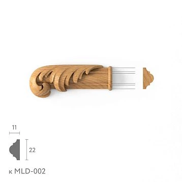
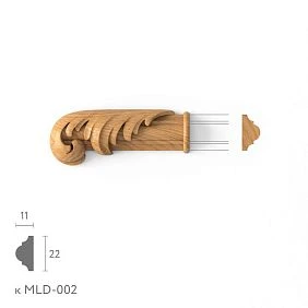
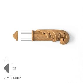
| MLD-002 | 22 × 11 mm | Compact cross-section, precise clamping required without bringing hands near the blade |
| MLD-031 | 60 × 9 mm | Longitudinal flutes; groove edges should be protected |
| MLD-032 | 60 × 8 mm | Wavy face surface; stable support is especially important |
| K-045 | 40 × 10 or 60 × 14 mm | Carved "Braid" ornament, vulnerable protrusions and the need to align the pattern |
MLD-002: narrow moulding for small frames
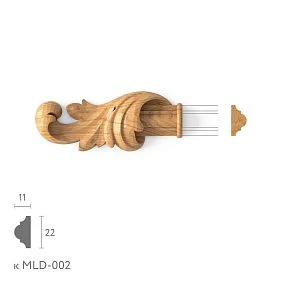
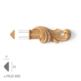
Wooden Moulding MLD-002 available in oak, beech and MDF versions, cross-section 22 × 11 mm. For solid wood, the catalogue lists lengths of 1000 and 2400 mm; for MDF, 2600 mm.
Working with a narrow profile requires no less discipline than with a wide one. Installing a short piece without a suitable clamp is dangerous: the operator has little room to position their hands safely. For a large batch of small frames, it is sensible to use pre-prepared, machine-approved tooling or to order cutting.
MLD-031: fluted profile
MLD-031 moulding has a cross-section of 60 × 9 mm. The repeating longitudinal grooves create a rhythm on the surface, but they are not a separate ornament with a repeat along the strip.
When cutting, the clean edges of the flutes must be preserved, especially where they meet the mitred end. Uneven support on the reverse side can cause the piece to vibrate slightly and leave chips on the thin decorative ridges. For oak and beech, the main table in the product card specifies a length of 2400 mm, and for the MDF version, 2600 mm; available options should be checked before ordering.
MLD-032: wave-shaped profile
MLD-032 has a cross-section of 60 × 8 mm. The wave-shaped form requires careful selection of the position on the machine: on an uneven decorative surface, the piece may rock if it is not supported by a suitable support.
On the finished rectangular corner, check that the relief lines continue. Even a slight deviation in the cut can be noticeable due to the mismatch of the longitudinal waves. As with the previous model, the product card lists items in oak, beech and MDF, but their lengths may differ.
K-045: "Kosichka" carved baguette
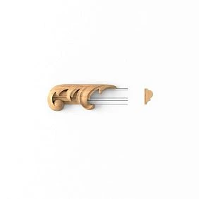
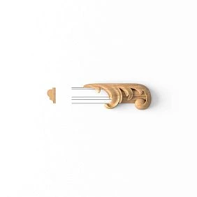
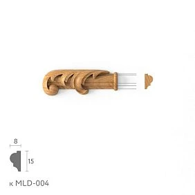
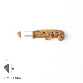
K-045 carved wooden baguette is available in oak and beech versions with cross-sections of 40 × 10 and 60 × 14 mm. The product card specifies lengths of 300 and 2000 mm.
This is a different type of task. Not only must the thin parts of the ornament be protected from tear-out, but the cut position must also be chosen so that the "Kosichka" does not break off with a random fragment on the most visible corner. When ordering samples and long pieces, allow material for a test cut and a joint check.
How to calculate the moulding allowance for cutting
Geometric length of the frame
For a frame with an outer size of 800 × 1200 mm and straight sides, the preliminary linear footage is:
L = 2 × (800 + 1200) = 4000 mm, that is, 4 linear meters.
The calculation assumes measurement along the agreed line, for example between the outer vertices of the miters. With a different dimensioning system, the blank lengths will need to be recalculated.
Cutting map for 2400 mm long strips
For a smooth molding with four parts with outer dimensions of 1200, 1200, 800 and 800 mm, two 2400 mm strips are theoretically suitable:
| Plank | Parts | Sum of finished lengths | Remainder before accounting for saw kerfs |
|---|---|---|---|
| № 1 | 1200 + 800 mm | 2000 мм | 400 мм |
| № 2 | 1200 + 800 mm | 2000 мм | 400 мм |
This is an example of a preliminary distribution, not a finished production map. The actual allowances for preliminary end trimming, the saw kerf width and possible final adjustment must be added to each part. For profiles with a directional pattern, the selection of segments may change the layout.
General rule: first check which whole parts can be obtained from each factory strip, and only then divide the total linear footage by its length.
An example where calculating by linear footage is misleading
Four solid pieces of 1250 mm are required. The total length is 5000 mm. If the strips are 2400 mm long, simple division gives slightly more than two strips, and there may be a temptation to buy three.
But from one such blank you cannot get two 1250 mm segments even without accounting for the saw kerf: 1250 + 1250 = 2500 mm. Therefore, at least four strips will be required if lengthwise joints are not acceptable.
For the carved K-045 with a factory length of 2000 mm, the cutting map will be different. There, selecting the area for the pattern may require additional offsets from the end and increase waste. A percentage allowance does not replace the selection of specific parts; a detailed system can be found in the article on calculating moldings and the cutting map.
How to reduce losses of expensive carved baguette
Distribute long parts first, and short ones after the ornament has been matched. Number the source strips and mark on them the available areas with suitable pattern endings. For repeating products, do not mix up already matched sets.
Do not make the first experimental cut on the most expensive part intended for the visible center of the composition. It is better to provide a separate test offcut in advance and record the tool setup result. If the saw is then readjusted, the accuracy is checked again with a test joint.
Typical mistakes when sawing wooden moldings
| Mistake | What's happening | How to prevent and fix |
|---|---|---|
| Dull or unsuitable blade | Fiber tear-out, uneven end face, possible burn marks | Check the purpose and condition of the tooling; make a new test cut |
| Insufficient clamping | Part shifting, incorrect angle, risk of dangerous kickback | Use the standard or approved clamp, ensure stable support |
| Thin profile without support | Chipping, damage to the profile | Use suitable support fixtures; do not clamp fragile protrusions |
| Orientation mixed up | Paired parts do not join with the correct miters | Mark the outer edge, the frame side, and the cutting direction |
| No test cut | Expensive trim is damaged due to incorrect settings | Check the tool on a sample of the same cross-section |
| Carved pattern not taken into account | Ornament accidentally breaks off at the corner | Agree on the motif placement before cutting; replace the section if necessary |
| Sanding too aggressively | Edge is rounded over and a gap appeared in the miter joint | Remove only burrs; if the error is serious, redo the cut |
If a chip is found on a finished part, first determine whether it affects the geometry of the joint and the appearance under the future finish. A small burr is removed locally. A tear-out at the outer tip of the miter may require a new cut; this needs the remaining allowance. You cannot promise an invisible repair of a large defect on oak under clear lacquer.
Frequently asked questions
What is the best way to cut wooden moldings?
For regular, precise cutting, a well-maintained miter saw with a suitable blade for clean crosscuts and reliable clamping is convenient. For a small number of compact parts, a miter box with a hand saw is possible. The choice depends on the cross-section, length and required accuracy. For carved molding, the name of the tool matters least; what matters most is the ability to support the profile without damaging the ornament.
Can carved trim be cut with a hand saw?
Yes, if the miter box and clamping device allow the workpiece to be held safely and the blade is intended for clean woodwork. Complex deep relief and wide bevel cuts require more time and control when working by hand. Do not try to compensate for an unstable workpiece by pressing hard with your hand near the blade: it is better to prepare reliable tooling or take it to a workshop.
How do you cut a wooden molding at 45 degrees?
Determine which edge will be the outer one, mark the direction of the left and right miters, make test cuts and check the joint dry. For a rectangular frame, both mating ends are usually cut at 45°. But the machine scale readings should be confirmed with a square and a test angle. Do not start the final cutting of the whole set until the first pair of parts fits together without a noticeable gap.
Why does oak molding chip when sawed?
The cause may be the grain direction, the condition of the blade, poor support at the exit edge or vibration of the workpiece. Large vessels and the uneven structure of oak affect the nature of the damage, but the species itself does not mean inevitable chips. Compare the results of test cuts, check the tooling and the position of the part. If tear-outs persist, change the preparation and safe support rather than increasing feed force.
How do you properly cut beech baguette?
Use a sharp, undamaged blade for a clean crosscut, secure the profile on a stable support, and make a test cut. With beech, pay especially close attention to the condition of the fibers at the edge and the cleanliness of the surface under a clear finish. If the molding is carved, it is important not to crush the protruding pattern with the clamp. After cutting, it is enough to carefully remove burrs while preserving the plane of the miter joint.
Can a laminate blade be used?
The purpose stated on the packaging does not provide sufficient grounds for selection. Check whether the blade manufacturer permits cutting natural wood and whether its design is suitable for the specific miter saw. The diameter, arbor, permissible speed, and other tool requirements must match. If compatibility is not confirmed, it is better to choose tooling expressly intended for clean crosscutting of solid wood.
How should a wooden end grain be treated after sawing?
First remove dust and small burrs, taking care not to alter the geometry. For enamel, the end grain is prepared and primed according to the chosen coating system. For stain, oil, or clear lacquer, carry out a test finish on an offcut of the same species, since end grain may absorb the product differently. If there is a large tear-out on it, finishing materials will not replace a repeat precise cut.
How can the ornament be preserved when joining carved molding?
Lay out the whole strips, mark the beginning and continuation of characteristic elements, and align their position with the dimensions of the frame. Then make a test corner from the selected sections. With a directional pattern, the piece cannot be rotated arbitrarily: adjacent ends may not match. It is also important to choose the cut location in advance so that a thin relief element is not left unsupported at the blade exit.
How much material allowance is needed for cutting?
There is no single percentage for all profiles. The quantity is determined by the length of the factory strips, the size of the whole pieces, the kerf width, the number of corners, and the requirements for the pattern. For smooth molding, it is enough to draw up a cutting plan with allowances; for carved molding, additionally tie the pieces to the motifs on specific strips. Before ordering, it is useful to set aside separate material for test joints.
A clean cut begins before the saw is switched on
A clean end grain is achieved not by force or subsequent thick-layer puttying. The result is determined by the condition of the cutting tool, the stability of the workpiece, support of the wood fibers, precise marking, and checking the angle on a test joint. For carved wooden mouldings, one more task is added — to preserve the fragile areas of the ornament and to match the pattern of adjacent pieces.
Before ordering, check not only the linear footage but also the factory lengths, material, and cross-section of each profile. The STAVROS range includes compact wooden mouldings for frames, fluted and wave-shaped products, as well as carved wooden mouldings made of solid wood. If the cutting plan is drawn up in advance, it is easier to select the right workpieces, preserve the decorative pattern, and avoid waste when sawing.