Article Contents:
- What data is needed before calculation
- Outer dimension, inner field and frame axis
- From each frame to a list of physical segments
- How to get the net linear footage
- Cuts and process waste
- Cutting plan for four frames
- Why eight strips really aren't enough
- How to create a cutting plan for another project
- Multiple rooms: separate verification, shared cutting plan
- How to distinguish useful offcuts from waste
- Why a flat 10% does not replace calculation
- Reserve is calculated separately from process waste
- How corners and ends change part lengths
- Ornamental linear trim: lengths alone are not enough
- How to calculate molding for an arch
- Do not combine different finishes under one linear meter total
- What to recalculate after a project change
- What a molding calculator must account for
- How to move from quantity to cost
- 12 molding calculation mistakes
- When the quantity is ready to order
Eight solid pieces of 1600 mm each make 12.8 linear meters of molding. If you divide the total length by the product length of 2600 mm and round up, you get five strips. But you cannot get two such pieces from one strip: you need at least eight. The total material length is not enough to verify the purchase quantity.
Molding calculation for a project starts with the approved layout and a specific profile. Each frame is broken down into physical parts, the length of each is determined, they are distributed across product strips, and only then is the agreed reserve added. The result is the number of whole products from which the project can actually be assembled.
What data is needed before calculation
Prepare up-to-date wall elevations, a list of frames, the approved article number, and information about joints. For the profile, you need width A, depth C, and product length L. Width is used to convert frame dimensions into part lengths, depth is used to check abutments, and the length of the supplied product is used directly in cutting.
The following versions are found in STAVROS product cards:
| Molding | A × C × L, mm | What to keep for the calculation |
|---|---|---|
| MLDPU-002 | 22 × 11 × 2600 | Specific cross-section and length of 2600 mm |
| MLDPU-003 | 35 × 12 × 2600 | Greater width with the same product length |
| MLDPU-027 | 14 × 9 × 2600 or 20 × 12 × 2600 | Selected size, since the item has variants |
Before choosing a profile, you can estimate the preliminary linear footage. The final number of strips is calculated after the item, size specification, and components are fixed. The same product length does not yet make different moldings interchangeable.




Outer dimension, inner opening, and frame axis
The label "900 × 1600" on the drawing is ambiguous until the measurement line is defined. It could be the outer dimension, the clear inner opening, or the distance between the geometric axes of the profile.
For a simple rectangular frame with 45° miters, it is convenient to compile the parts list by the long outer edges. With a constant profile width A, the conversion is as follows:
- the same length along the long edge is obtained from the outer dimension;
- A is added to the dimension along the geometric axes;
- 2 × A is added to the inner opening dimension.
For example, with a width of 22 mm, the entry "900 × 1600" will yield different cut lengths:
| Dimension line on the drawing | Horizontal length, mm | Vertical length, mm |
|---|---|---|
| External dimension | 900 | 1600 |
| Geometric axes of the profile | 922 | 1622 |
| Inner field | 944 | 1644 |
Here the axis runs through the middle of the profile width. The formulas apply to a standard rectangular frame without decorative corners or special joints. For a different joint, the length is determined from its drawing, and machining allowances are accounted for separately.
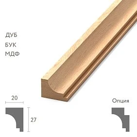
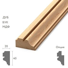
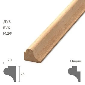
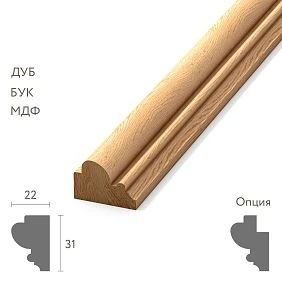
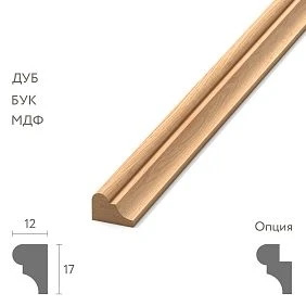
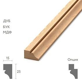
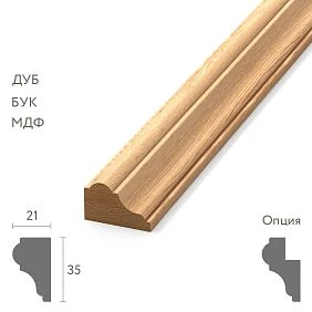
Our factory also produces:
From each frame to the list of physical segments
Let's consider a hypothetical project consisting of four frames. All dimensions are specified by the outer overall size; a single smooth profile MLDPU-002 is used, and the parts must be one-piece. Frames P1 and P2 measure 900 × 1600 mm, P3 — 1200 × 2100 mm, P4 — 650 × 1200 mm.
Each frame requires two horizontals and two verticals. First, keep track of which parts belong to which frame, even if their lengths repeat.
| Part designation | Frame | Length along the long edge, mm | Quantity, pcs. |
|---|---|---|---|
| P1-G | P1 | 900 | 2 |
| P1-V | P1 | 1600 | 2 |
| P2-G | T2 | 900 | 2 |
| P2-V | T2 | 1600 | 2 |
| P3-G | T3 | 1200 | 2 |
| P3-V | T3 | 2100 | 2 |
| P4-G | P4 | 650 | 2 |
| P4-V | P4 | 1200 | 2 |
16 parts were generated. For trimming, add the profile orientation to the end lines of the diagram. If two parts of the same length have different joints, they cannot be merged into a single generic line.
The rule of "four pieces per frame" applies to independent closed contours. If adjacent fields are separated by a single shared profile, that section is counted once. When two separate strips with a gap run between the fields, both are included in the list. On the layout, it is useful to assign each physical line its own designation so that a shared boundary is not counted twice.
The perimeter of the room is not suitable for this calculation: it does not describe the internal frames, repeating fields, and vertical divisions. You need to count the lines that will actually be assembled from molding.
Get Consultation
How to get the clean linear footage
Multiply the length of each segment by its quantity and add up the results. In our example, after grouping identical lengths, we get:
4 × 900 + 4 × 1600 + 4 × 1200 + 2 × 2100 + 2 × 650 = 20,300 mm, or 20.3 m.
This is the sum of the finished lengths of the pieces along the accepted measurement line. It is needed for project control and material balance. It does not yet include losses for cuts, end preparation, and unused offcuts.
Check the result a second way, by frames: F1 and F2 give 5 m each, F3 — 6.6 m, F4 — 3.7 m. The sum again comes to 20.3 m. A mismatch between the two counts indicates a missed row, a quantity error, or a mix-up of measurement lines.
Dividing 20.3 by 2.6 with rounding up gives eight strips. This number is a lower estimate based only on total length. Whether all 16 pieces can be obtained from eight items still needs to be checked.
Cuts and process losses
A rectangular frame has four corner joints and eight piece ends prepared for these joints. Counting it as "four cuts" is incorrect. The number of saw passes depends on the chosen technology, including the preliminary preparation of the blanks.
The cutting map accounts for the kerf width, end preparation, and losses due to the sequence of angled cuts. The possibility of combining adjacent cuts is checked with regard to the section orientation: savings on the layout must not require an unacceptable rotation of the part.
For the following training calculation, let us assume conditional total technological losses of 20 mm per strip. This is a simplified initial condition of the example, not a standard for MLDPU-002 or any tool. In a working calculation, the value is determined from the actual cutting pattern. Then, to accommodate the finished lengths in our example, 2580 mm out of 2600 mm remain.
Cutting map for four frames
Let us distribute the parts across the strips. The lengths in one row refer to one source strip; the "Quantity" column indicates how many times this pattern is repeated.
| Strip numbers | Segments from one strip, mm | Number of planks | Remainder from one strip after conditional losses, mm |
|---|---|---|---|
| 1–2 | 2100 | 2 | 480 |
| 3–6 | 1600 + 900 | 4 | 80 |
| 7–8 | 1200 + 1200 | 2 | 180 |
| 9 | 650 + 650 | 1 | 1280 |
Check not only the sum of lengths but also the composition of the resulting parts: four of 900 mm, four of 1600 mm, four of 1200 mm, two of 2100 mm, and two of 650 mm. A matching total footage alone does not confirm that the map contains all the required sizes and quantities.
The selected pattern requires nine strips of 2600 mm, that is, 23.4 m of supplied material. All 16 parts from the original list are placed.
Control balance: 20.3 m of finished lengths + 0.18 m of conditional technological losses + 2.92 m of remainders = 23.4 m. The remainders are shown separately here: some of them may still be useful for other sections of the same profile.
Why eight boards really aren't enough
In this example, nine is not a random result of the first cutting attempt. Two parts of 2100 mm each take up a separate board: even the shortest required part of 650 mm won't fit alongside them.
Four parts of 1600 mm take up four more boards. Offcuts of 1200 mm won't fit alongside them, so four such parts require at least two additional boards. All eight are already taken.
At most one offcut from the remaining lengths of 900 and 650 mm can be added to each 1600 mm part. That gives four slots for six parts. The boards with two 1200 mm offcuts have no room for them either. Therefore, eight boards are not enough even without processing losses; a ninth is necessary given the specified solid parts.
It's useful to run this check when the estimator proposes a particularly tight cutting plan. Matching total meters is not enough — every part must have its own place.
How to build a cutting map for another project
Start with the longest offcuts: they have fewer placement options. For each long part, select suitable short ones while preserving room for processing. Then distribute the remaining medium and short elements.
Don't push the calculation right up to the nominal length by zeroing out losses. Combining finished parts across the full 2600 mm leaves room for processing only when this is confirmed by a specific layout and the condition of the original item. If in doubt, test the cutting plan before purchasing the entire batch.
After the first pass, review the largest leftovers and try rearranging a few parts. Sorting by descending length is convenient for manual calculation, but it doesn't guarantee the minimum number of boards for any given set.
If a part is longer than the available stock board, rearranging won't help. You need to agree on an intermediate joint, a different supplied size, or a change in layout. You must not split a solid part in the program on your own just to get a nice-looking result.
Multiple rooms: separate checks, shared cutting plan
First, calculate each wall and room separately to verify that the layouts are complete. Then combine identical profile versions across the entire project while keeping the installation location label for each part.
For example, suppose the living room needs six 1600 mm pieces and the hallway needs six 800 mm pieces. With a 2600 mm strip length and the waste assumed in the example, a separate calculation gives six strips for the living room and two for the hallway: three short pieces from each.
A shared cutting plan allows each strip to yield 1600 + 800 mm. Six strips are enough instead of eight. This saving is possible if the material, item code, version and finish match, and the work organization allows pieces to be transferred between rooms.
How to tell a usable offcut from waste
An offcut is assessed after the necessary cuts and a condition check. In the main sheet, the longest offcut is 1280 mm. For a new 1200 mm piece it may be sufficient if the remaining space is enough for preparation; for a 1600 mm part it is not.
Match offcuts against the entire work list, including rooms not yet started. Label the item code, size version, length and storage location. Otherwise a usable fragment can easily get lost among similar scraps.
An allocated offcut cannot be promised to two areas at once. In the work sheet it must have a single assignment or be marked "free". Length suitability also does not replace checking for damage, orientation and pattern.
Why a flat 10% does not replace a calculation
Let's return to the eight full 1600 mm pieces from the beginning of the article. The net length is 12.8 m. Even if you first add 10%, you get 14.08 m; dividing by 2.6 m and rounding up gives six strips. For eight full parts, you still need at least eight.
The percentage does not account for the distribution of lengths. A project with short elements may make good use of offcuts, whereas long one-piece parts leave significant unused portions of each strip. The same linear meterage in these cases results in a different order.
First obtain a feasible cutting map. Then decide whether additional material is needed for damage, a processing error, a trial assembly, or future repair. The allowance must serve a specific purpose, not conceal the absence of a calculation.
Reserve is calculated separately from process waste
Process waste is already built into the cutting plan: it is the material consumed while performing the specified operations. The reserve remains for additional needs. Offcuts after cutting are not equivalent to a whole spare strip.
For example, our map leaves 2.92 m of fragments, but none of them can replace a damaged part 2100 mm long. If the project requires the ability to remake such a part, one additional whole strip can be agreed. Then the original requirement will be nine working strips and one reserve, ten in total.
Do not add the same requirement twice. If a strip has already been allocated for a trial assembly and will be used up, list it as a separate line; it will not remain as a whole repair reserve. If an existing suitable offcut genuinely covers an agreed spare part, reflect this in the calculation as well.
This is a conditional decision for the example. For another project the reserve may differ: the complexity of the joints, the availability of reordering, the storage method, and the purpose of the spare material are taken into account. Separately record who approved the reserve and which situations it is intended to cover.
How corners and ends change part lengths
A 45° cut applies to the rectangular frame under consideration on a single plane. Inside and outside room corners, T-junctions, and open ends require their own schemes. The parts list must make both boundaries of each segment clear.
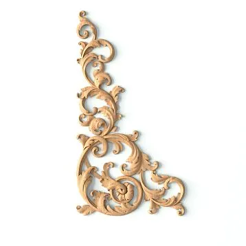
If used Decor for Molding, first establish the junction points. A shaped corner may replace part of the linear profile, while an overlay of another type may overlap it. You cannot subtract the full dimensions of any decorative part from the perimeter: the connection method is determined by the specific joint.
Corners, center overlays and paired end pieces are counted in pieces. Left and right parts are recorded separately with their own item codes. Their quantity affects the package contents, and their actual position affects the lengths of the adjoining trim.
Ornamental trim: length alone is not enough
for ornamental trim the position of the pattern is added to the cutting chart. You need to know the ornament repeat, direction, starting point and the position of the motif near a corner or the central axis of the composition.
An offcut may match in length and not match in pattern. Imagine a 850 mm fragment and a required part of 800 mm. If aligning the motif requires trimming 70 mm at the start, 780 mm will remain even before the other operations. Such an offcut cannot be used, although the initial length comparison looked favorable.
First agree on the placement of the ornament, then distribute the parts. The same length with a different pattern start is treated as a different cutting job. You cannot transfer the scheme of a smooth molding to an ornamental one without this check.
How to calculate molding for an arch
For an arc, the length of the specified path is calculated. The opening width measures the distance between the ends and does not replace the length of the curved section.
For a conventional semicircle with a design path radius of 600 mm, the length is π × 600 ≈ 1885 mm. The distance between the ends is 1200 mm. If only the width is included in the calculation, the arc section will be significantly undercounted.
For an arbitrary curve, obtain the length from the working drawing, after first checking the units and the absence of gaps or duplicate lines. Converting this geometry into the blank length is agreed with the assembly and installation conditions of the specific product.
Flexible polyurethane molding is handled separately from the straight version. Confirm the permissible bending radius and direction, the product length and the connection to straight sections. The mere presence of an arc in the model does not confirm that the selected profile can be bent.
Do not combine different versions under a single linear meterage
After checking the rooms, group the parts by the full product designation: article number, size, material, version, and finish. Each group will have its own commercial length, set of segments, and cutting map.
This also applies to selections from the section polyurethane molding. The entry “decorative profile — 64 m” does not show how much of each product is required. The remainder of a wide profile cannot be used for a short part of a narrow one just because the lengths match.
Grouping is also retained when the price or delivery length is the same. If deliveries are split by stages, decide in advance whether remainders can be stored and transferred between them. Without such an order, the calculated savings may not materialize on site.
What to recalculate after a project change
Replacing a profile requires checking which original dimensions are fixed. If the inner field is retained, increasing the molding width will lengthen the parts along the outer edge. If the outer dimension is retained, the lengths may stay the same, but the field and joints will change.
Changing the commercial length requires a new cutting map even if the list of parts is unchanged. Moving the frame, adding an overlay, or changing an arched section affects the corresponding rows. Note the date and revision of the layout on which the calculation is based.
To verify the geometry, use DWG drawings and STAVROS 3D models, comparing the file with the selected version. After revision, repeat the part quantity check: the old row must not remain in the order together with the new one that replaced it.
What a molding calculator should account for
A simple calculator that takes the total linear footage and a waste percentage is suitable for a preliminary estimate. Purchasing requires a calculation based on individual lengths and the number of pieces.
A working tool should account for the product length, processing losses, available offcuts, and the prohibition of intermediate joints where continuous sections are required. Ornamental profiles and complex angles need additional conditions or manual verification.
You can test how it works using the example of eight pieces of 1600 mm from 2600 mm planks. If the program suggests five or six items, it has not solved the task of producing continuous segments. Even a correct result requires a cutting map: the user must see which plank each piece comes from.
When importing data from a spreadsheet, check the units. The values 1600 mm and 1.6 m must be treated as one length in the calculation, and a row with a quantity of "2" as two pieces.
How to go from quantity to cost
If the product is sold in whole planks, the cost of the linear profile is calculated as the number of planks ordered × the current price of one plank. The net footage of 20.3 m does not replace the nine planks to purchase in the main example.
With one agreed spare plank, the cost is calculated for ten items. If some suitable material is already on site, check its condition and include it in the map as available stock. You cannot reduce the order by the total length of random offcuts without allocating the pieces.
Piece decor, installation materials, packaging, and delivery are accounted for separately based on the actual order composition. The price per linear meter can help compare options, but the final budget depends on the number of whole items and the suitability of the cutting plan. Availability and lead time are confirmed for the selected finish and quantity.
12 molding calculation mistakes
Before sending data to purchasing, check the following places:
- The item code has not yet been approved. The calculation remains preliminary until a finish is selected.
- The room perimeter was used instead of the layout. Check all actual decor lines.
- Only the total number of meters is available. Restore the lengths and the number of physical parts.
- The measurement line is not specified. Clarify the outer dimension, inner field, or axis.
- The total footage was simply divided by the product length. Confirm the result with a cutting plan.
- The program split the long section automatically. Agree on the joint or keep the continuity requirement.
- Remainders are not matched across rooms. Check the combined list for a single finish.
- The usual 10% was added. Separate the working cut from a justified reserve.
- The corner dimension was subtracted without checking the joint. Find the actual junction points.
- Left and right parts are mixed up. Separate the item codes and quantities.
- The ornament is calculated as a smooth strip. Check the start of the pattern and the trimming.
- After the project was changed, the old order was saved. Verify the calculation against the current layout.
When the quantity is ready to order
The calculation is complete when all parts are distributed across the strips, and every deviation from the clean meterage is explained by technology, remnants, or reserve. For our conditional project, the result looks like this:
| Indicator | Result |
|---|---|
| Profile | MLDPU-002, 22 × 11 × 2600 mm |
| finished parts | 16 pcs. for four frames |
| Total of finished lengths | 20.3 m |
| Strips according to the cutting map | 9 pcs. |
| Conditional technological losses | 0.18 m for the entire cutting layout |
| Offcuts after cutting | 2.92 m in total |
| Additional reserve, if approved | 1 whole plank |
| Quantity with this reserve | 10 strips, 26 m of supplied material |
The result is transferred to the moulding specification together with the cutting map and the current layout reference. This way the kit assembler sees the rationale for the quantity, and the contractor sees the purpose of each strip.
After checking, you can buy polyurethane moldings for the approved layout. Related items are selected in the catalog moldings from polyurethane, the terms of professional cooperation are clarified on the page for designers and architects.
The order includes the number of whole strips of each version and individual piece items. On site, the list of cut segments is kept: it is this list that links the purchased material with the frame dimensions and the sequence of work.