





































Article Contents:
- Why a beautiful wall elevation is not yet a specification
- What the difference between a drawing and a purchase looks like
- Why long verticals and short horizontals cannot be mixed in a single figure
- Why you cannot mix several coordinate systems
- What the zero point gives the buyer
- Why the module needs to be coded
- M‑02 by the door
- M‑03 in the corner
- M‑04 by the wardrobe
- Why this matters for a wholesale batch
- What can be tied to a single axis
- When molding actually covers a seam
- Why the actual profile matters for the module geometry
- The cornice cannot be calculated from the ceiling plan alone
- Why the end module must be coded separately
- Corner module as a separate code
- Standard door module M-D01
- Module M-04 next to the wardrobe
- What to do if the furniture changed after ordering
- Why the set preserves its structure
- Why the set is convenient for the warehouse
- Why the end modules of a corridor must not be hidden in reserve
- Example
- What is allocated first
- Example with MLD-059 in oak, 2400 mm long
- Why a universal waste percentage cannot be promised
- Why modularity still reduces the risk of waste
- PLT and KZ are cut separately from MLD
- Why a layout version is mandatory
- The warehouse must see more than just MLD
- Minimum marking code
- Why a modular system is convenient for phased delivery
- The door was moved by 150 mm
- The wardrobe became 100 mm wider
- The ceiling became 100 mm higher
- Only the finish changed
- Why local recalculation reduces the risk of new errors
- Why a small profile sample is not enough
- The actual consumption of the control wall also needs to be compared with the calculation
- Practical example: 80 standard rooms turn into a repeatable parts list
- How meters turn into the real number of source strips
- Why edge parts cannot be added as a “percentage”
- 18 errors that most often break a modular specification
- Checklist before a wholesale order
- Decision tree: can a module be replicated without a separate recalculation
- Final algorithm from layout to wholesale order
- What the final request to the supplier should look like
- How to link moldings, skirting boards, and cornices in a single procurement system
- How to arrange the general wholesale part of an order without losing product-level detail
- How to check floor completeness before handing over to installers
- How to account for usable leftovers after the first phase
- When it is beneficial to split one module into two production sub-assemblies
- Why MLD‑059, PLT‑006, and KZ‑001 cannot be considered the same “wooden decor”
- What the version of a typical room should look like after a project change
- What to do if the control wall shows the wrong rhythm
- The final commercial reconciliation should verify completeness, not just the invoice amount
- Frequently Asked Questions

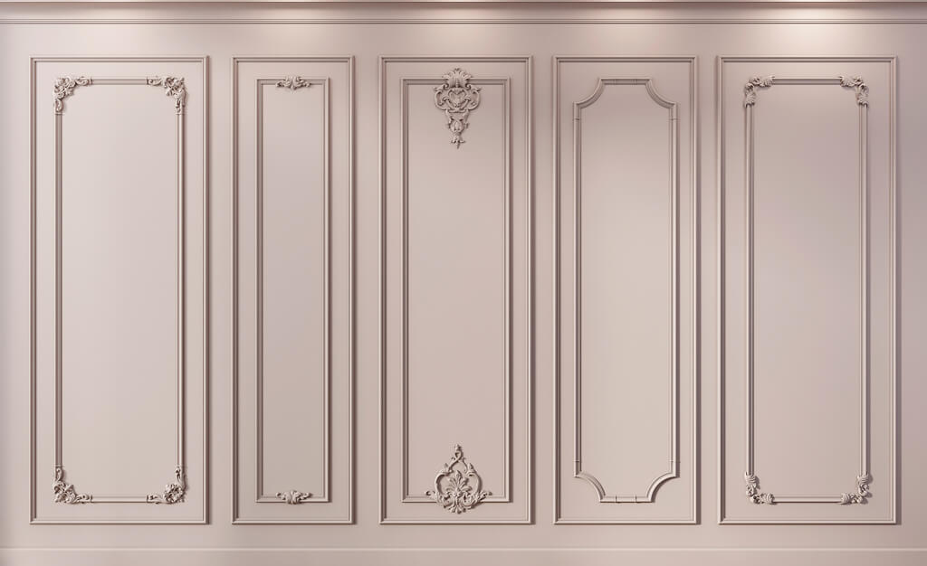
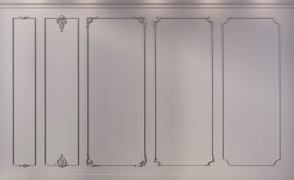
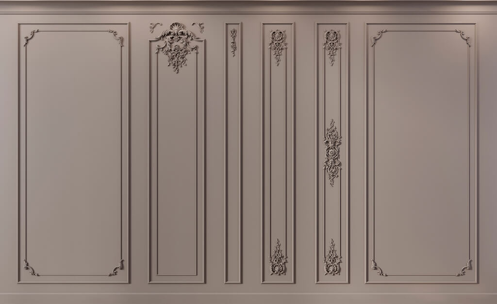
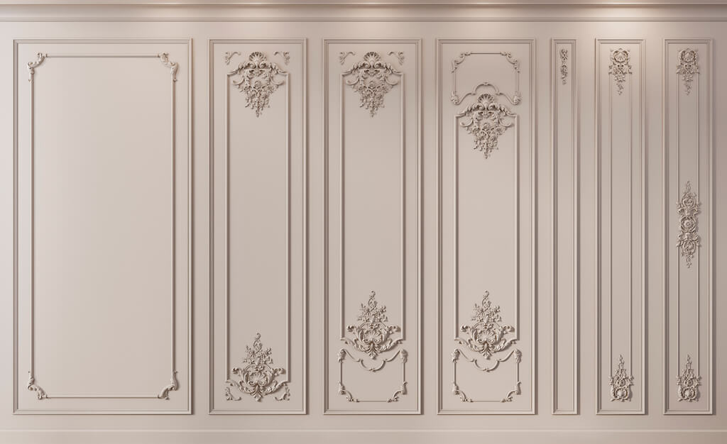
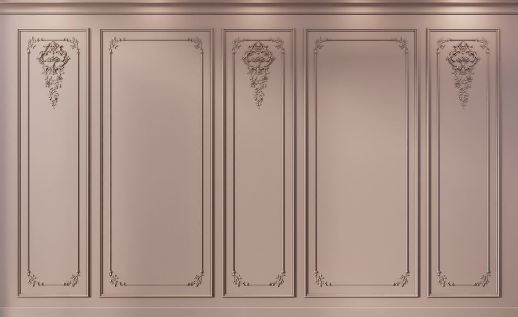
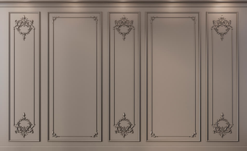
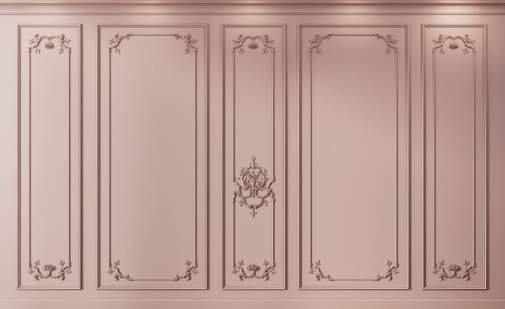
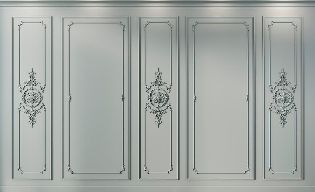
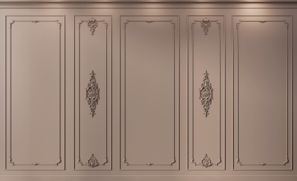
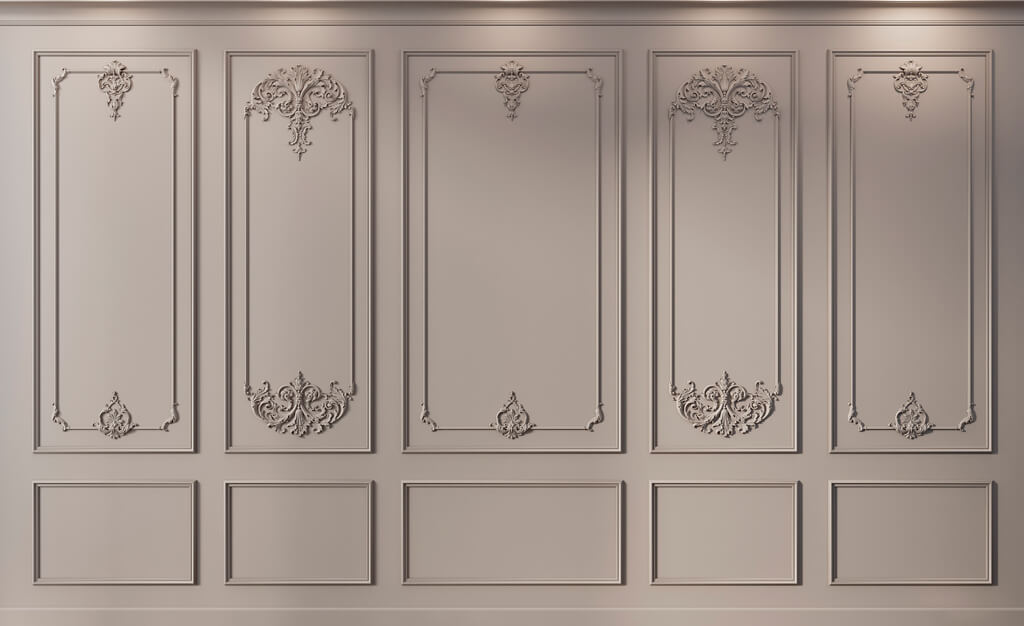
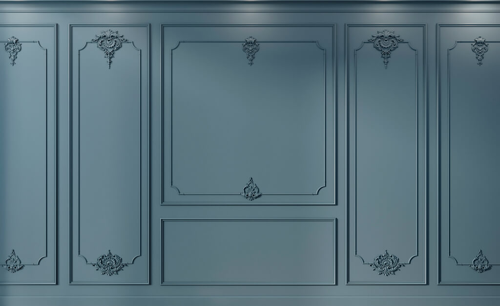
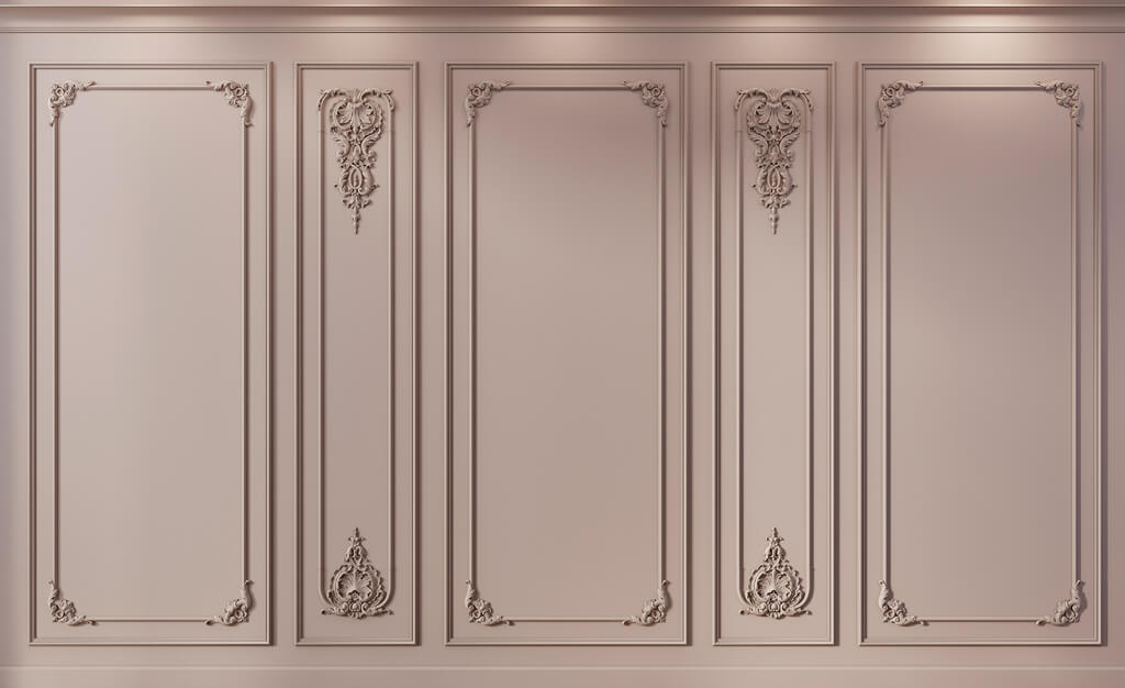
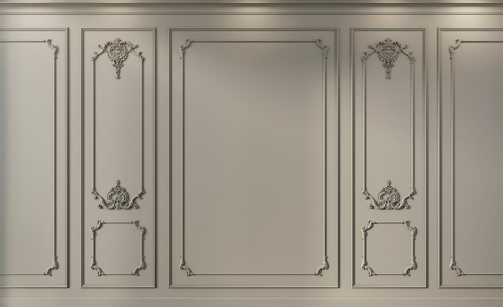
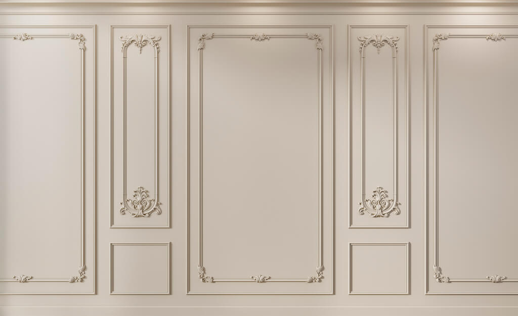
On a designer's elevation, the wall looks complete: baseboard at the bottom, rectangular panels above, vertical moldings between them, then a horizontal band and ceiling cornice. The rhythm is even, doors are neatly integrated into the composition, and the corners look symmetrical. But for purchasing, such a drawing still means almost nothing.
What the buyer needs is not a "beautiful wall" but a set of repeatable parts: how many verticals of one molding, how many horizontals of another, which baseboard sections repeat, where short extensions appear, which cornice completes the composition, which elements belong to a standard module, and which belong to a door, corner, or end module.
Therefore, buying decorative wooden trim wholesale is only correct after converting the elevation into a structure:
ROOM → WALL → ZERO POINT → MODULE → PART → SKU → MATERIAL → FINISH → FINISHED LENGTH → QUANTITY → CUTTING MAP → KITTING.
Main principle:
THE ELEVATION SHOWS THE COMPOSITION. THE SPECIFICATION MUST DESCRIBE EVERY REPEATABLE PART OF THAT COMPOSITION.


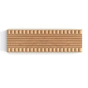

Why a beautiful wall elevation is not yet a specification
On the drawing, the designer may show seven rectangular frames, a door, a baseboard, and a cornice. For visual approval, this is enough. For wholesale purchasing, questions remain:
- which exact MLD is used on the verticals;
- whether the same MLD runs along the horizontal;
- whether the vertical lengths are the same in all sections;
- what happens near the door;
- what are the dimensions of the end module;
- which PLT finishes the bottom;
- which KZ finishes the top;
- is there a separate band between the lower and upper parts;
- which elements repeat 80 times, and which exist in a single instance.
Until these answers are available, the phrase “molding — 1800 m” only creates a budget estimate. It does not make it possible to manufacture, accept, and distribute the material by room.
STAVROS already has a separate article about moldings for wall panels, where the choice of profile and the boiserie composition are covered. Here the task begins later: the composition has already been approved, and it needs to be translated into an executable wholesale order.
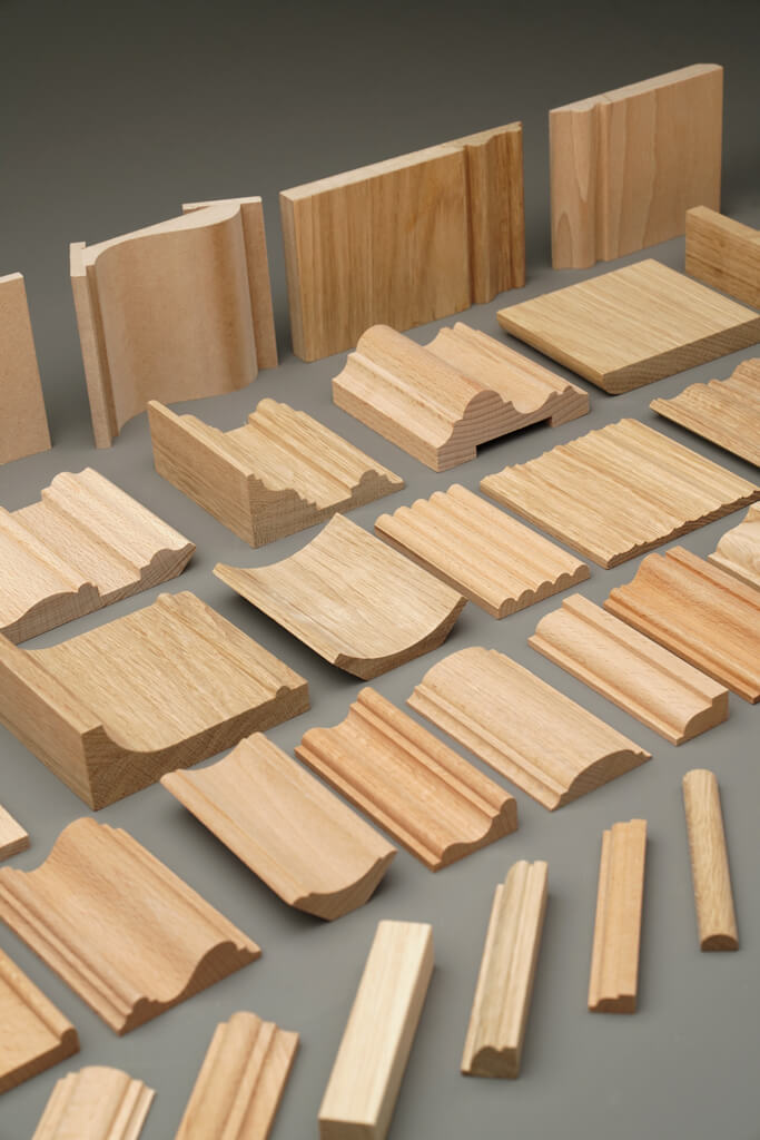



What the difference between the drawing and the purchase looks like
The drawing says:
“There are six identical panels on the wall.”
The purchase order should say:
- MLD‑A, vertical 1120 mm — 12 pcs.;
- MLD‑A, horizontal 620 mm — 12 pcs.;
- PLT‑B, lower section 4800 mm — per cutting plan;
- MLD‑C, upper band 4800 mm — per cutting plan;
- KZ‑D, cornice 4800 mm — per cutting plan.
Only the second option can be verified and ordered.
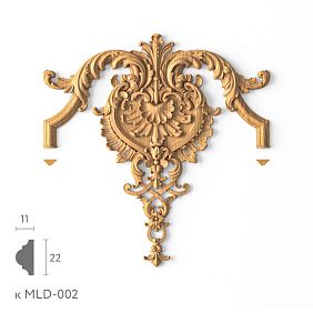
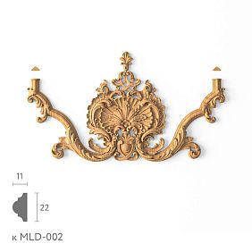
Our factory also produces:


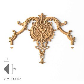


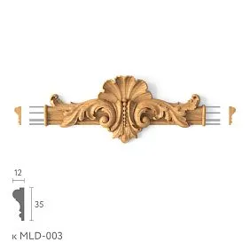
Linear meters do not show the structure of a panel wall
Two projects can consume the same 1800 m of moulding and have completely different procurement complexity.
Project A:
- 240 identical verticals;
- 240 identical horizontals;
- several standard door modules.
Project B:
- dozens of different lengths;
- many end filler strips;
- asymmetric angles;
- different room heights;
- a few furniture exceptions.
The net linear meters are the same. Cutting, the number of full planks, and the risk of color mismatch differ.
Therefore linear products wholesale on a panel-based project, it is better to calculate by repeatable parts, and use meters as a checksum.
Get Consultation
Why long verticals and short horizontals cannot be mixed in one figure
For a source plank 2400 mm long, a 2100 mm vertical almost consumes a whole piece. A 550 mm horizontal can be obtained from the remainder of another part. Their identical meterage has different production value.
It is the structure of lengths that determines the actual order.
Each wall must have a single zero point
So that the layout can be recalculated after changing a door, cabinet, or end panel, all wall coordinates must have a single source.
Example:
LEFT FINISHED CORNER OF THE WALL = 0.
From it are set:
- start of the first vertical;
- edges of the panel fields;
- a doorway;
- a niche;
- boundary of the built-in wardrobe;
- outer moldings;
- skirting endpoint markers;
- start and end of horizontal bands.
Why you shouldn't mix multiple coordinate systems
If the first vertical is set from the left corner, the door from the center of the wall, the second frame from the door, and the end section from the right corner, any change turns the elevation into a chain of manual recalculations.
With a single zero point, shifting the door by 150 mm changes a specific set of coordinates. The system remains verifiable.
What the zero point gives the purchaser
It allows you to see where each length came from. This is especially important in the dispute “why should the vertical be 1180 and not 1160 mm” — the answer can be reconstructed from the approved wall geometry.
For the purchaser, a module is a repeatable set of parts
For the designer, a modular grid is a way to create rhythm. For the purchaser, a module is a ready-made unit of configuration.
For example:
M‑01 — standard wall section.
It includes:
- 2 verticals MLD‑A;
- 2 horizontals MLD‑A;
- section of the lower plinth PLT‑B;
- section of the upper band MLD‑C;
- section of the cornice KZ‑D.
Now, instead of “about 14 m of molding is needed for the wall,” a clear set appears.
| Part code | Article | Purpose | Length | M‑01 |
|---|---|---|---|---|
| V-01 | MLD‑A | Vertical | ___ | 2 |
| G-01 | MLD‑A | Horizontal | ___ | 2 |
| P‑01 | PLT‑B | Bottom line | ___ | across the module width |
| PS‑01 | MLD‑C | Upper belt | ___ | across the module width |
| K‑01 | KZ‑D | Cornice | ___ | across the module width |
After that, a wall of six identical sections is described as:
M‑01 × 6.
Why the module needs to be coded
The code becomes a common language for the designer, purchaser, warehouse, and installer. The phrase “we need another M‑01” is more unambiguous than “we need two verticals and two horizontals like in the previous item.”
Standard, door, corner, and furniture modules cannot be considered identical
Even if the entire project uses a single MLD profile, the geometry of the parts around the door, corner, and cabinet differs.
It is convenient to create:
- M‑01 — standard;
- M‑02 — next to the door;
- M‑03 — corner;
- M‑04 — next to built-in furniture;
- M‑01K — end module.
M‑02 next to the door
The opening takes up part of a standard section. Horizontal lines become shorter, the vertical may shift, and the panel edge changes.
M‑03 in the corner
The last field rarely has the same width as the central ones. You need to know the design offset from the corner and the connection to the second wall.
M‑04 next to the wardrobe
The wardrobe can replace part of the decorative wall. One vertical disappears, the skirting ends earlier, and the upper band changes length.
Why this matters for a wholesale batch
If all four options are counted as M-01, the central modules will be counted correctly, while all edges and junctions will produce a systematic shortfall or overage.
Vertical axes must maintain rhythm between modules
The main mistake in a modular wall is not the profile itself, but a shift in rhythm. If in one room the verticals stand on the same axes, while in the neighboring standard room they are shifted by a few centimeters, the interior stops being perceived as serial.
Therefore, the elevation drawing records not only the dimensions of the frames, but also the coordinates of the vertical axes.
For example:
- axis V-01 — 620 mm from the zero point;
- axis V-02 — 1240 mm;
- axis V-03 — 1860 mm;
- the doorway begins at 2480 mm.
If the door is shifted, the specific set of axes next to it is updated. The rest of the wall remains unchanged.
What can be aligned to a single axis
Only if the design provides for it, the following may align on a single vertical line:
- molding;
- the edge of the casing;
- the panel seam;
- the axis of the decorative overlay;
- the boundary of the furniture portal.
Such alignment must be designed in advance. You cannot count on the installer to "adjust it on site."
Panel seams must be marked on the elevation before calculating the decorative trim
A wall panel has its own technical grid. A decorative frame has its own compositional grid. Sometimes they coincide, sometimes they do not.
If the panel seams are not marked on the elevation in advance, the molding may accidentally:
- fall within 10–20 mm of the seam;
- cross it at an awkward angle;
- leave a narrow visible strip;
- partially cover the joint;
- create a double vertical line.
This is not just an aesthetic problem. If the molding has to be shifted after the grid is approved, the lengths of the horizontals and the edge modules change.
When the molding actually covers the seam
Only if the system is designed that way. STAVROS treats the molding as an element of the framing system and as a possible profile for finishing joints, but this does not mean that every panel seam must automatically be covered with a decorative profile.
For choosing the element itself, there is material about moldings for wall panels. In the procurement article, the seam already acts as a coordinate that affects the module and the details.
The baseboard must be included in the layout from the very beginning
The baseboard defines the lower boundary of the entire composition. If its height or projection changes after the frames are calculated, the lower margins change as well.
Therefore, you cannot first design all the frames and then "fit the baseboard in from below."
It is necessary to record:
- article number;
- height;
- thickness;
- projection relative to the panel;
- top line;
- endpoints;
- junction with door casings;
- junction with vertical moldings.
Why the actual profile matters for module geometry
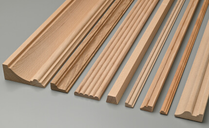
PLT‑006, for example, is 100 mm in height; for MDF its cross-section is specified as 100 × 16 mm with a length of 2600 mm, while for beech and oak it is 100 × 15 mm with a length of 2400 mm. Even with the same geometric role, the material changes the purchasing configuration.
If the lower margin of the panel should begin 140 mm above the floor, and the baseboard is 100 mm high, then according to the adopted scheme there remains 40 mm between the top of the baseboard and the frame. If a different profile 80 mm high is installed later, the free margin becomes 60 mm. This is a different composition.
To select the lower profile, you can use the material on Skirting for wall panels, but after approval the height must become part of the modular calculation.
The upper band and ceiling cornice affect the height of all verticals
The upper part of the wall often consists of two different elements:
- a horizontal molding that completes the panel zone;
- a ceiling cornice that completes the wall at the ceiling.
If the upper band is lowered by 50 mm, all vertical fields below it may change. If the cornice becomes larger, the free field between the upper frame and the ceiling also decreases.
Therefore, the height of vertical elements is not calculated separately from the upper system.
The cornice cannot be calculated from the ceiling plan alone
The ceiling plan shows the route along the wall. The elevation shows doors, cabinets, portals, and changes in the panel system.
In the section with a floor-to-ceiling cabinet, the cornice may end earlier. At a portal, it may get a different termination. In a corner, it may transition to the adjacent wall.
For the top line, it is useful to use a specific wooden cornice KZ‑001 or another approved KZ, but the final linear footage is taken from the layouts and the plan simultaneously.
The purchaser cannot align the width of the panel fields independently
A wall is rarely divided into a perfect number of identical modules. After accounting for the door, corners, and cabinet, there may be 280 mm, 430 mm, or another non-standard field left.
There are several architectural strategies:
- keep the central panels identical and enlarge the outer ones;
- keep the central axis and reduce the outer ones;
- create a symmetrical composition around the door;
- change the width of several fields gradually;
- leave a separate end module.
The buyer does not choose the strategy. Their task is to accurately translate the approved decision into details.
Why the end module needs to be coded separately
Because it is the one that most often differs from the central ones. For example:
M‑01 — standard 620 mm.
M‑01K — end 410 mm.
If the wall is recorded as M‑01 × 7, the edge will be calculated incorrectly.
An internal corner connects two layouts and two end modules
A wall does not end in a vacuum. An internal corner connects two compositions.
You need to determine:
- offset of the end vertical from the corner on wall A;
- offset on wall B;
- width of the edge margins;
- whether the horizontal band continues;
- how the baseboard runs;
- how the cornice runs.
If each wall is designed separately, it is easy to end up with a wide margin on one side and a narrow random strip on the other near the corner.
Corner module as a separate code
You can use:
M-U01 — internal corner type 1.
It includes parts of both adjoining walls, if such an approach is convenient for production.
Or each wall keeps its own edge M-01K. The main thing is that the logic should be unambiguous.
The outer corner requires even stricter control of rhythm
At the outer corner, both walls are visible simultaneously. Any random difference in the width of the edge margins is perceived more strongly.
Need to coordinate:
- continuation of the vertical rhythm;
- width of the edge panels;
- position of the last vertical;
- lines of the upper band;
- joint of the baseboard;
- joint of the cornice.
If a single one is used wooden molding, this simplifies the product part, but does not eliminate the need to calculate different lengths.
The door opening must be part of the modular grid from the very first drawing
The mistake is to first build a perfect panel grid and then overlay the door on top of it.
The door defines:
- the starting coordinate;
- opening width;
- Baseboards;
- height;
- the portal, if present;
- the visible wall sections on the sides.
Special elements almost always appear near the door:
- shortened horizontal lines;
- separate vertical lines;
- a different end module;
- special skirting board section;
- interruption or change of the upper band.
Standard door module M‑D01
If the same door unit is repeated in 80 rooms, it is advantageous to count it once.
M‑D01 × 80.
Within M‑D01, all lengths and article numbers are already known. When the door is changed, one module version is updated instead of 80 separate rows.
Built-in furniture must be included in the layout before purchasing trim
A wardrobe, furniture portal, or built-in cabinet can replace an entire section of a decorative wall. If furniture appears after the mouldings are calculated, the wholesale schedule quickly becomes outdated.
You need to know in advance:
- where the furniture begins;
- whether it reaches the ceiling;
- whether the skirting board continues in front of it;
- whether the vertical molding ends at its edge;
- whether the upper band continues;
- whether the ceiling cornice runs above the furniture.
Let's imagine that a standard wall had M‑01 × 5. Later, a 1400 mm wide wardrobe occupies the two outermost modules. The order cannot be left unchanged: verticals, horizontals, part of the skirting board, and possibly the upper band disappear.
Module M‑04 next to the wardrobe
If such a unit repeats, it is coded separately. Then the project does not say "in this number the wardrobe is slightly shorter than the wall," but:
M‑04 × 80.
This is especially convenient for hotel and residential projects with standard built-in furniture.
What to do if the furniture changed after ordering
Do not recalculate the entire object automatically. It is necessary to determine which walls and modules are affected. If the cabinet is repeated in all 80 rooms, the standard M-04 is changed once, then the new version is replicated.
Mirrored rooms can be combined only after checking the edge parts
A mirrored layout does not always require a separate specification. If the door, cabinet, window, and corners are simply mirrored symmetrically, the set of parts may remain the same.
But you need to check:
- whether the lengths of the edge margins match;
- whether there is an asymmetrical door portal;
- whether the built-in furniture is the same;
- whether the direction of the panel seams changes;
- whether another external corner appears;
- whether the ends of the skirting board and cornice match.
If all lengths are the same, TP-01 and TP-01-mirrored can have the same procurement configuration. If the edge parts differ, a separate version is created.
A typical room should be counted as a set of modules
After all the walls of one room have been converted into typical modules, a room set is formed.
For example:
TR‑01:
- M‑01 × 6;
- M‑D01 × 1;
- M‑U01 × 2;
- M‑04 × 1;
- skirting board PLT‑B;
- upper band MLD‑C;
- cornice KZ‑D.
Now a hotel with 80 identical rooms is described as:
TP‑01 × 80.
This is much more powerful than multiplying the linear meterage of one room by 80.
Why the kit preserves the structure
If one vertical is missing, you can see which module is not covered. If you count only 40 m of molding per room, it is impossible to identify the missing part.
Why the kit is convenient for the warehouse
The warehouse can assemble material by rooms or floors. It is not necessary to physically pack each M‑01 separately, but the bill of materials should allow this to be done.
| Set | Module | Quantity per room | Number of rooms | Total modules |
|---|---|---|---|---|
| TP‑01 | M‑01 | 6 | 80 | 480 |
| TP‑01 | M‑D01 | 1 | 80 | 80 |
| TP‑01 | M‑U01 | 2 | 80 | 160 |
| TP‑01 | M‑04 | 1 | 80 | 80 |
A long corridor requires its own module, not a copy of the room grid
A corridor wall often contains dozens of repeating sections between doors. Modularity is especially advantageous here.
For example:
M‑COR × 42.
But the beginning and end of the corridor almost always differ from the central module.
Therefore, the following are additionally introduced:
- M‑COR‑L — left end;
- M‑COR‑R — right end;
- M‑D01 — standard door;
- M‑COR‑U — turn or corner section.
Why end corridor modules cannot be hidden in the reserve
If the central module repeats 42 times, while the end one appears only once, there is a temptation to count 42 standard ones and “add a little extra.” This is weak logic.
The end module has specific parts and must be a specific line item. The reserve is needed for unforeseen situations, not for known non-standard elements in advance.
Room height changes the vertical parts and the entire module
Module M‑01 from a room with a height of 2700 mm cannot be automatically transferred to a hall of 3200 mm.
Changes:
- height of verticals;
- distance from the baseboard to the upper rail;
- size of the upper field;
- cornice position;
- possible number of horizontal divisions.
If the same decorative language is used in rooms of different heights, related versions are created:
M‑01A — height 2700.
M‑01B — height 3200.
Product codes may match. Part lengths do not.
The same profile in MDF and solid wood — different purchasing lines
Even if the decorative grid is completely identical, the material changes the purchasing configuration.
A good example is MLD‑059. Its cross-section of 17 × 10 mm is the same, but MDF is produced in lengths of 2600 mm, while beech and oak are 2400 mm.
This means: the same M‑01, when switching from MDF to oak, must be recalculated for cutting.
You cannot simply replace the material in a line and keep the number of planks.
Example
For M-01 you need:
- 2 verticals of 1180 mm each;
- 2 horizontals of 620 mm each.
Per module:
2 × 1180 + 2 × 620 = 3600 mm of clean length.
At a length of 2600 mm, one plank can yield 1180 + 1180 = 2360 mm, leaving about 240 mm before accounting for cuts. The horizontals will have to come from another plank or be combined with parts from other modules.
At a length of 2400 mm, 1180 + 1180 = 2360 mm uses the product almost completely. The offcut map is already different.
In a large production run, the difference scales across hundreds of identical parts.
For a broad catalog, you can use Decorative wooden trim, but the material and commercial length must be fixed in each line.
One module in two colors becomes two purchasing versions
The geometry may be the same, but the finish is different.
For example:
M‑01 / O‑01 — white finish.
M‑01 / O‑02 — natural oak.
The parts list by lengths may be the same. Purchasing card and warehouse accounting are separate.
The O‑01 remainder cannot be used for O‑02 after the final finish.
Therefore, the finish code must accompany the module throughout the entire chain: project → order → packaging → warehouse → issue → reorder.
The cut list is converted into the parts list in four levels
This is the central methodology of the entire article.
Level 1: room → walls.
TP‑01 contains walls C‑01, C‑02, C‑03, C‑04.
Level 2: wall → modules.
S‑01 = M‑01 × 4 + M‑D01 × 1 + M‑01K × 1.
Level 3: module → parts.
M‑01 = B‑01 × 2 + G‑01 × 2 + section PLT‑B + section MLD‑C + section KZ‑D.
Level 4: part → SKU + length + quantity.
B‑01 = MLD‑059 / oak / O‑01 / 1180 mm / 240 pcs.
After this, the beautiful wall composition turns into an accurate production bill of materials.
| Part code | Article | Material | Finish | Finished length | Quantity | Where it is used |
|---|---|---|---|---|---|---|
| V-01 | MLD‑059 | Oak | O-01 | 1180 мм | 240 | M‑01 |
| G-01 | MLD‑059 | Oak | O-01 | 620 мм | 240 | M‑01 |
| P‑01 | PLT‑006 | Oak | O-01 | along the wall | By cutting | TP‑01 |
| K‑01 | KZ‑001 | Oak | O-01 | along the wall | By cutting | TP‑01 |
This is already a document that can be checked before payment.
The cutting map is built only after receiving the parts list
Total linear meters is too early a stage for cutting. First, you need to get the full list of parts for one SKU.
For MLD‑059, for example, the cutting list may contain:
- verticals 1180 mm — 240 pcs.;
- horizontals 620 mm — 240 pcs.;
- door verticals 980 mm — 80 pcs.;
- outer horizontals 410 mm — 160 pcs.;
- short filler strips 280 mm — 80 pcs.
Only now can the source strips be optimized.
What is distributed first
- the longest parts;
- standard long ones;
- medium;
- short;
- outer fillers.
The reason is simple: a long part has fewer options for source material. Short ones can be made from offcuts.
Example with MLD-059 in oak, 2400 mm long
Two verticals of 1180 mm each:
1180 + 1180 = 2360 mm.
An offcut of about 40 mm before accounting for the actual cut is almost useless.
One vertical 1180 and one horizontal 620:
1180 + 620 = 1800 mm.
About 600 mm remains. This offcut can cover a 410 mm horizontal or a 280 mm filler.
Therefore, the optimal cutting plan for the entire series does not necessarily reproduce a single M-01 entirely from one plank. For production, it is more efficient to group identical lengths across all modules.
Why a universal waste percentage cannot be promised
Waste depends on:
- commercial length;
- the set of finished lengths;
- the number of end modules;
- door modules;
- material;
- the finish;
- the ability to use offcuts in other parts.
In one project, serial production yields a very tight cutting layout. In another, long verticals almost entirely consume the original strips. That's why a 10% reserve cannot be considered a rule.
Why modularity still reduces the risk of waste
Not because it automatically creates a fixed low percentage. But because the number of identical parts becomes large and predictable.
For example, one vertical is repeated 240 times. Production can build a stable cutting algorithm in advance and clearly see what to do with the offcuts.
PLT and KZ are cut separately from MLD
Skirting board, moulding and cornice are different article numbers. They cannot be combined into one cutting map just because they belong to the same wall system.
PLT‑006 in oak has a length of 2400 mm, MLD‑059 in oak is also 2400 mm, but physically they are different profiles. The offcut of one does not replace the other.
KZ‑001 may have a different commercial length in the selected finish. Its calculation is separate.
The master specification must store the entire path from room to part
After the modular calculation, one main document is needed that does not force you to search for data across dozens of drawings.
Minimum structure:
| Room | Wall | Module | Detail | Article | Material | Finish | Length | Quantity |
|---|---|---|---|---|---|---|---|---|
| TP‑01 | S-01 | M‑01 | V-01 | MLD‑059 | Oak | O-01 | 1180 | ___ |
| TP‑01 | S-01 | M‑01 | G-01 | MLD‑059 | Oak | O-01 | 620 | ___ |
| TP‑01 | All walls | — | P‑01 | PLT‑006 | Oak | O-01 | by sections | ___ |
| TP‑01 | All walls | — | K‑01 | KZ‑001 | Oak | O-01 | by sections | ___ |
This document must be linked to the current version of the elevations.
Why the elevation version is mandatory
If the designer moved a door, but the purchaser uses an old parts list, the numbers formally look neat and at the same time are already incorrect.
Therefore, alongside the master specification, the following is recorded:
- revision number;
- date;
- which walls have been changed;
- which modules have been updated;
- which version is considered current.
The warehouse must see more than just the MLD
Label:
MLD‑059 / 240 pcs.
is weak.
More useful:
MLD‑059 / TP‑01 / M‑01 / V‑01 / oak / O‑01 / 1180 mm.
It is not necessary to print all fields in large type on every plank. But the packaging unit and the internal document must make it possible to restore the purpose.
Minimum marking code
BODY → FLOOR → ROOM → MODULE → SKU.
For example:
K1 / F2 / NUMBER-A / M‑01 / MLD‑059.
A finish code is added for different finishes.
Why the modular system is convenient for phased delivery
You can order:
Floor 2 = 20 sets of TP‑01.
Within the master specification, it is automatically known how many M‑01, M‑D01, PLT and KZ are required for these twenty rooms.
There is no need to manually reassemble hundreds of individual profiles for each phase.
For the general commercial group construction materials wholesale this detail remains within the product package, while the general anchor leads to the STAVROS main page according to the accepted rule.
Project changes should recalculate the affected modules, not the entire object manually
The modular structure is especially strong after revisions.
The door was moved by 150 mm
There is no need to recalculate 80 rooms individually again.
Changes:
- M‑D01;
- adjacent M‑01K;
- several horizontals;
- coordinates of verticals near the opening;
- possibly, a section of skirting board.
If the change is repeated across all 80 units, the M-D01 version is updated once and then replicated.
The wardrobe became 100 mm wider
M-04 is updated. If the wardrobe is identical across all units, 80 independent calculations are again not required.
The ceiling became 100 mm higher
Vertical lengths change and, possibly, the position of the upper rail. This is already a version of the entire module by height.
Only the finish changed
The geometry of the parts may remain the same, but the procurement version is split by finish.
Why local recalculation reduces the risk of new errors
When one door changes, a full manual recalculation of all walls opens up the possibility of accidentally changing something that did not require changing. A modular system localizes the revision.
For a phased project delivery of finishing materials must reference the current module revision, otherwise the old geometry may return in the next batch.
A control wall before a large batch checks the entire chain at once
Before purchasing thousands of meters, it is useful to assemble one typical wall or reference room.
It shows:
- correctness of the zero point;
- module rhythm;
- width of the edge margins;
- door module;
- corner transitions;
- plinth;
- upper band;
- cornice;
- actual finish;
- chiaroscuro;
- actual consumption.
Why a small profile sample is not enough
The sample responds whether MLD is liked. The control wall responds whether the entire system works correctly.
It may reveal:
- the end field is too narrow;
- the vertical almost coincides with the panel seam, but not completely;
- the door casing conflicts with the molding;
- the PLT protrudes too much relative to the panel;
- the upper band is lowered too low;
- the cornice makes the top of the wall overloaded.
Fixing one wall is cheaper than 80 typical rooms.
The actual consumption of the control wall also needs to be compared with the calculation
If one standard room according to the schedule requires 34 m of MLD, while the control installation consistently required 35.2 m due to unaccounted extras, the difference is:
1.2 × 80 = 96 m of net length.
And after conversion to whole planks, the procurement difference may be higher.
Therefore, the control section is not only a visual but also a quantitative test.
Practical example: 80 standard rooms turn into a repeatable parts schedule
Let's consider a hypothetical hotel project. Each room has four walls. Two walls contain standard modules, one contains a door unit, and the fourth contains a built-in wardrobe and an end module.
After approval of the elevations, we get:
- M‑01 — 6 pcs. per room;
- M‑D01 — 1 pc.;
- M‑04 — 1 pc.;
- M-U01 — 2 corner nodes;
- PLT-006 — along the lower contour;
- MLD-C — along the upper band;
- KZ-001 — along the ceiling contour.
For 80 rooms:
M-01 = 6 × 80 = 480 modules.
M-D01 = 80.
M-04 = 80.
M-U01 = 160.
If M-01 contains two verticals V-01 and two horizontals G-01, only the central type yields:
V‑01: 480 × 2 = 960 parts.
G‑01: 480 × 2 = 960 parts.
This is why the total number of meters hides the main advantage of a serial object: hundreds of identical parts can be planned as an industrial repeatable batch.
How meters turn into the real number of source planks
For example, let V‑01 = 1180 mm, G‑01 = 620 mm, and MLD‑059 made of oak with a length of 2400 mm is used.
Net length of M‑01 parts:
960 × 1.18 + 960 × 0.62 = 1132.8 + 595.2 = 1728 m.
But these are only the central modules. Door and end parts are added separately.
If you cut two verticals from one plank:
1180 + 1180 = 2360 mm.
For 960 verticals, 480 source planks are required for this combination alone.
Horizontals can be grouped, for example in threes:
620 × 3 = 1860 mm.
About 540 mm remains before accounting for cuts, which can be used for an edge filler if its length fits.
The number of strips for horizontals depends on the actual map of short parts. This is where the modular schedule saves: leftovers can be used not randomly, but according to the known positions M‑01K, M‑D01, and M‑04.
Why edge parts cannot be added as a "percentage"
Suppose each room has two edge horizontals of 410 mm. For 80 rooms:
2 × 80 = 160 parts of 410 mm.
The net length is only 65.6 m. But these 160 parts are ideal consumers of leftovers from long and medium elements.
If instead a conditional 5% reserve is added, production loses specific information and may simultaneously:
- buy extra length;
- not get the required number of edge parts;
- discard suitable leftovers;
- then place an urgent additional order.
A pre-known non-standard element is not a reserve, but a full-fledged specification part.
18 mistakes that most often break a modular specification
1. Counting only total linear meters. Reason — meters are easier to get from the estimate. Consequence — it is impossible to verify the composition of parts and the cutting plan. Prevention — a parts list before purchasing.
2. Not using elevations. Reason — the purchaser works only from the room plan. Consequence — doors, panels, and vertical axes are lost. Prevention — every wall system must have an up-to-date elevation.
3. Not setting a zero point. Reason — dimensions are taken from different objects. Consequence — after changing a door, the coordinates stop matching. Prevention — one finished wall corner = 0.
4. Using multiple coordinate systems. Reason — different designers measure in the way that is convenient for them. Consequence — the same vertical gets different values. Prevention — a single wall base.
5. Not coding modules. Reason — it seems that the frames are all the same anyway. Consequence — the warehouse and production do not understand which set belongs to which wall. Prevention — M‑01, M‑D01, M‑U01, etc.
6. Treating the end module as a standard one. Reason — it looks similar. Consequence — the end panel ends up the wrong width. Prevention — M‑01K with its own lengths.
7. Ignore panel seams. Cause — decorative layout is designed separately from the panel layout. Consequence — the molding conflicts with the joints. Prevention — seams on the elevation before calculating parts.
8. Calculate the molding first, then add the baseboard later. Cause — the molding seems to be the main decor. Consequence — the height of the lower margins changes after approval. Prevention — PLT is included in the initial grid.
9. Do not account for the door unit. Cause — the door is considered a separate section. Consequence — horizontals and verticals near the door casing do not align. Prevention — standard M-D01.
10. Do not account for built-in furniture. Cause — the furniture project arrives later. Consequence — the ordered linear trim turns out to be excessive or too short. Prevention — wardrobe boundaries before issuing the wholesale specification.
11. Transfer a module between rooms of different heights. Cause — the desire to unify. Consequence — verticals and upper margins become disproportionate. Prevention — height-specific versions.
12. Mix MDF, beech, and oak in one line. Cause — the article number is the same. Consequence — commercial lengths and finishes differ. Prevention — material as a separate field.
13. Mix finishes. Cause — the geometry is the same. Consequence — the remainder of one color group is mistakenly considered a reserve for another. Prevention — finish code in the module and on the packaging.
14. Build the cutting plan based on the total sum of meters. Cause
Checklist before the wholesale order
| Check | Status |
|---|---|
| Current elevations approved | ___ |
| The zero point of each wall is defined | ___ |
| The modular grid is approved | ___ |
| The dimensions of all panel fields are fixed | ___ |
| Panel seams are applied | ___ |
| M-01 and other standard modules are created | ___ |
| Edge modules are highlighted | ___ |
| Internal corners are coordinated | ___ |
| External corners are coordinated | ___ |
| Doors and casings are confirmed | ___ |
| Built-in furniture is confirmed | ___ |
| Skirting board selected | ___ |
| Horizontal moldings selected | ___ |
| Vertical moldings selected | ___ |
| Cornice selected | ___ |
| Materials confirmed | ___ |
| Finishes confirmed | ___ |
| Typical rooms calculated | ___ |
| Quantity of each type determined | ___ |
| Parts list generated | ___ |
| Cutting map ready | ___ |
| Marking determined | ___ |
| Delivery sequence has been determined | ___ |
| Control section assembled | ___ |
Decision tree: can the module be replicated without a separate recalculation
Does the wall size match?
No → separate elevation or module version.
Yes → check the door.
Do the door position and size match?
No → separate M-D.
Yes → check the built-in furniture.
Do the furniture boundaries match?
No → separate M‑04.
Yes → check the room height.
Does the height match?
No → new version of vertical parts.
Yes → check the material and finish.
Are the item codes, materials, and finishes the same?
Yes → the room can be replicated as TP‑01.
No → the geometry may be shared, but the purchasing lines are split.
Final algorithm from layout to wholesale order
GET CURRENT LAYOUTS → SET ZERO POINTS → PLACE DOORS, SEAMS, CORNERS, AND FURNITURE → APPROVE BASEBOARD → APPROVE MOLDINGS AND UPPER BAND → APPROVE CORNICE → SPLIT WALLS INTO MODULES → CODE M‑01, M‑D01, M‑U01, M‑04, AND EDGE MODULES → CONVERT MODULES INTO PARTS → ASSIGN ITEM CODE, MATERIAL, FINISH, AND FINISHED LENGTH TO PARTS → ASSEMBLE TYPICAL ROOM TP‑01 → MULTIPLY BY QUANTITY → COMPILE MASTER PARTS LIST → BUILD CUTTING PLAN FOR EACH ITEM CODE → COUNT WHOLE PRODUCTS → ADD DELIBERATE RESERVE → APPROVE LABELING → CHECK CONTROL WALL → RELEASE WHOLESALE BATCH.
What the final request to the supplier should look like
Not:
“Molding — 1800 m, skirting — 900 m, cornice — 700 m.”
And, for example:
- MLD‑059 / oak / O‑01 / 2400 mm / parts V‑01 and G‑01 / number of whole strips according to the cutting plan;
- PLT‑006 / oak / O‑01 / 2400 mm / TP‑01 / quantity;
- KZ‑001 / oak / selected commercial length / O‑01 / TP‑01 / quantity;
- separate reserve;
- delivery queue;
- substitution rule.
The catalog can be used for the product Wooden trim. If a broad commercial scenario is needed, buy trim and molding wholesale can be done after the modular specification has already been assembled.
How to link moldings, skirting boards, and cornices in a single procurement system
If a wall profile has not yet been selected, use moulding wholesale or the profile article about moldings for panels.
If you need to select the bottom line, Baseboard and other types of trim require special transportation conditions. is considered a separate product group, but in a modular wall its dimensions must be coordinated before calculating the frames.
For the top line cornices wholesale are selected by a specific SKU and then included in the overall wall set.
For panel and furniture systems, the following material is useful: wooden trim for wall panels: it explains the use of profiles, while the current methodology is responsible for the bulk bill of materials and cutting.
How to arrange the general wholesale part of an order without losing item-level detail
If the project is supplied as building materials Moscow wholesale, via finishing material suppliers, large supplier of building materials or building material suppliers, within the general contract a separate package of wooden decor still needs to be preserved. The same rule applies to Wholesale building material suppliers, wholesale building material suppliers, building materials supplier wholesale and scenario wholesale purchase of building materials: commercially, items can go in one order, but technically PLT, MLD, and KZ must remain separate lines. When comparing building materials at wholesale prices, when supplying finishing materials, ordering building materials wholesale from the manufacturer, scenarios wholesale purchase of building materials, as well as when purchasing construction materials wholesale, finishing materials wholesale, finishing materials wholesale moscow or simply materials in bulk this level of detail protects the project from hidden SKU substitution and picking errors.
As a result, the overall commercial order remains compact for the contract, but each wall system retains its own codes, materials, lengths, finishes, and substitution rules.
How to verify floor completeness before issuing to installers
Once the master specification is ready, it is useful to assemble not "bundles of moulding" but a set for a floor or group of rooms.
For example, floor 2 contains 20 identical TP‑01. This means the warehouse must confirm:
- M‑01 — 120 sets;
- M‑D01 — 20;
- M‑U01 — 40;
- M‑04 — 20;
- the full volume of PLT‑006 across twenty rooms;
- full volume of the upper rail;
- full volume of KZ‑001;
- separate reserve according to the approved scheme.
If the total MLD footage matches, but M‑D01 is only complete for 18 rooms, the floor is effectively not ready. That is why the number of complete modules matters more than a single sum of meters.
| Position | Needed per floor | Assembled | Shortage |
|---|---|---|---|
| M‑01 | 120 | 120 | 0 |
| M‑D01 | 20 | 18 | 2 |
| M‑U01 | 40 | 40 | 0 |
| M‑04 | 20 | 20 | 0 |
Such a check catches shortages before the installation crew starts opening packages and searching for missing parts on other floors.
How to account for usable leftovers after the first phase
After installing the first floor, there is no need to count all remaining MLD simply in linear meters. Leftovers are grouped by SKU, materials, finishes, and lengths.
For example:
- MLD‑059 / oak / O‑01 / full 2400 mm — 14 pcs.;
- leftovers 1000–1400 mm — 22 pcs.;
- remnants 600–999 mm — 35 pcs.;
- remnants 300–599 mm — 18 pcs.;
- shorter than 300 mm — process waste, if the project has no suitable parts.
Before the second batch, the master list of remaining parts is compared with this stock. If there are many 620 mm horizontals ahead, the 600–999 mm group has high value. If only long 2100 mm verticals remain, short offcuts hardly reduce the reorder.
This way the second batch is calculated based on the actual shortage, not by the formula “total requirement minus meters once purchased.”
When it is beneficial to split one module into two production subassemblies
Sometimes M‑01 is convenient for the architect as a single section, but for production it is better to split it into vertical and horizontal parts.
For example:
M‑01V — two verticals 1180 mm.
M‑01G — two horizontals 620 mm.
This is useful if the verticals are cut in a series from whole strips, while the horizontals are cut from remnants and other combinations. The architectural code M‑01 is preserved, while the production map gets a more convenient level of detail.
There is no need to split modules just for the sake of splitting. A sub-kit makes sense only where it improves cutting, packaging, or quantity control.
Why MLD‑059, PLT‑006, and KZ‑001 cannot be considered the same “wooden decor”
These items participate in one wall system, but have different roles and product geometry.
MLD‑059 — molding 17 × 10 mm, whose length depends on the material: MDF 2600 mm, beech and oak 2400 mm.
PLT‑006 — a universal profile with a cross-section of 100 × 16 mm for MDF and 100 × 15 mm for solid wood, also with lengths of 2600 and 2400 mm respectively.
KZ‑001 — an elaborate ceiling cornice with several product lengths depending on the material.
They can be summed up only at the level of the “total linear footage” budget. For ordering, cutting, warehouse, and reserve, these are three separate systems.
What the version of a standard room should look like after a project change
Suppose TP‑01 has already been calculated and ordered for the first 20 rooms. Then the door in all subsequent rooms was shifted by 150 mm.
There is no need to change the name of TP‑01 silently.
Useful:
- TP‑01 / R01 — original door;
- TP‑01 / R02 — door offset by 150 mm;
- M‑D01 / R02 — new lengths;
- M‑01K / R02 — new end module;
- date of transition to the new version;
- numbers where R01 is already installed.
This way, the warehouse will not issue old-version parts for a new room just because the molding article number is the same.
What to do if the control wall showed an incorrect rhythm
Do not try to compensate for the error during installation by trimming each module.
First, determine the cause:
- incorrect zero point;
- incorrect module width;
- door is not based on the current version;
- panel seams not accounted for;
- baseboard changed the height of the bottom margin;
- the end module was mistakenly treated as a standard one.
After that, the original geometry is corrected and a new version of the parts is released. Mass manual correction on site destroys the point of a modular system.
The final commercial reconciliation should verify completeness, not just the invoice total
Before payment, it is useful to compare three levels: the design module schedule, the production parts schedule, and the supplier's commercial proposal.
For example, the design requires 960 verticals V-01 and 960 horizontals G-01. The supplier may provide the correct total linear meters MLD-059, but incorrectly distribute the quantity among the lengths. The total rubles and meters will match, but it will be impossible to assemble all 480 M-01.
Therefore, the commercial check follows this chain:
MODULE → PART → SKU → LENGTH → NUMBER OF WHOLE PIECES → PRICE.
For each SKU it is useful to see:
- net requirement by parts;
- number of source strips according to the cutting plan;
- separate reserve;
- the material;
- finish;
- delivery queue;
- substitution rule.
If the supplier offers an alternative moulding, it must not quietly replace the base MLD in the total price. The alternative is entered as a separate line and again undergoes verification of frame size, angles, light and shadow, and cutting plan.
So wholesale trim products remain a manageable part of the large contract: commercially the order may be single, but technically each part retains its purpose.
for cornices wholesale from the manufacturer the same logic applies: KZ within TP-01 must not dissolve into the general line “wooden decor.”
Before sending the order to the supplier, it is useful to perform one more reverse check: go not from the room to the parts, but from each part to the rooms where it is used. If V-01 is specified in the quantity of 960 pieces, the system should show from which 480 modules M-01 it was derived and in which TP-01 these modules are located. Such reconciliation quickly detects double counting, a missed room, or a part that remained in the old version after the door was moved. For rare modules — corner, door, and end ones — reverse checking is especially useful, because their small quantity is easily lost against the background of thousands of meters of the main moulding. After it, the master specification becomes verifiable in both directions: from the wall to the purchase and from the purchasing line back to the specific wall.
Frequently Asked Questions
Can the entire panel wall be calculated only by area?
No. Area does not show the lengths of verticals, horizontals, end modules, door units, or the number of whole linear products.
Can you just calculate the linear meters of one standard room and multiply by 80?
For a preliminary budget — yes. For procurement, it's better to first create TP‑01 with modules and parts, check for exceptions, then replicate the set.
Does each module need its own manufacturer's article number?
No. M‑01 is an internal code for a geometric unit. Several actual article numbers from MLD, PLT, and KZ may be used within it.
Can a single molding cover both panel seams and decorative frames?
Only if the system is designed that way. You cannot automatically apply a decorative profile to every technical joint.
How do you calculate mirrored rooms?
First compare the edge parts, door, furniture, and corners. If the set of lengths matches completely, one set can be used. If not — a separate version.
Why does the material affect the number of strips if the profile is the same?
Because the commercial lengths may differ. For MLD‑059, MDF is 2600 mm, beech and oak are 2400 mm; for PLT‑006, the situation is similar regarding material lengths.
When should the cutting map be built?
After the full parts list is issued. Not based on total linear meters and not before the end modules are approved.
How do you handle changing a door by 150 mm?
Update the affected door and the adjacent end module. If the unit repeats 80 times, change the standard version once and replicate it.
What should be done with usable offcuts?
Link them to a specific SKU, material, finish, and length range. Short offcuts can cover filler strips and horizontal parts of other modules.
When is it too early to buy decorative trim?
If the elevations, doors, furniture, or modular grid are not yet finalized. Buying early at this stage turns design changes into physical mismatches.
For the next phase of the project, the same system can be reused: first verify that the elevations and module versions are up to date, then account for the whole offcuts from the first delivery, and only after that create a new cutting plan. This way, a repeat order does not start from scratch or from the total meterage, but from the already verified architectural structure of the project.
This structure also simplifies auditing actual consumption after installation and makes it possible to quickly find the cause of any systemic overspending.
After such preparation, buying decorative wooden trim in bulk means ordering not anonymous thousands of meters, but a verifiable set of PLT, MLD, and KZ from which you can assemble a specific number of walls, modules, and standard rooms without shifting the approved grid.