Article Contents:
- Composite ceiling cornice: one architectural solution, several purchasing items
- System data sheet SK-01: the document from which the calculation begins
- 1:1 cross-section drawing: why photographs of profiles are not enough
- Control fragment: assemble the system before launching a large batch
- One profile — one independent calculation
- Straight walls: when the linear meters of layers match, and when the consumption diverges
- Internal and external corners: one room corner — several system nodes
- Boxes, protrusions and niches: a small element that sharply increases the number of parts
- Endings: where and how the entire system should terminate
- Standard unit: one complete set first, then scaling
- Mirrored units: equal volume does not mean equal layout
- Lounges, halls and corridors: different routes — different systems
- Material and finish: a SKU without configuration may be an incomplete line
- Product length and cutting map: why total linear meters do not equal the number of planks
- An example where linear meters mislead
- Why another layer with similar linear meters can lay out better
- Layer A
- Layer B
- Layer C
- What happens if you add a hall
- 1. Ordering a composite cornice as a single line item
- 2. Not specifying the exact composition of the system
- 3. Calling all elements a “cornice”
- 4. Not making a 1:1 cross-section
- 5. Not assembling a control sample
- 6. Multiplying the total linear meters by the number of profiles
- 7. Treating an internal corner as a single node regardless of the number of layers
- 8. Treating all returns as identical
- 9. Assuming the same commercial length for all profiles
- 10. Create a single common cutting plan
- 11. Add one percent reserve to the entire system
- 12. Do not label the layers of one system
- 13. Accept a batch only by individual SKUs
- 14. Change one profile without checking joints
- 15. Send the old revision to the supplier
- 16. Calculate the cost only by the main cornice
- 17. Deliver layers at different times without connection to the installation schedule
- Can a composite cornice be calculated using only the total perimeter of the rooms?
- If the system has three profiles of the same length along the wall, can I simply order the same linear meters of each?
- Is it mandatory to make a physical sample of the entire system?
- Can a general 10% reserve be used?
- What should be done if one profile was replaced after the calculation?
- Should the left and right standard numbers be separated?
- How can I tell that the first batch is ready for installation?
- What is more important: linear meters or pieces?
- Can leftovers of different profiles be combined into a general reserve?
- When is it better to replace a composite cornice with a single profile?

If the top of a wall is finished not with a single trim but with a system of several profiles, the entry "cornice — 850 linear m" is almost useless for procurement. An architect may perceive such a molding as a single element, but the supplier, the order assembler, and the installation crew need separate line items: the lower transition molding, the main cornice, and the upper finishing profile — each with its own SKU, material, cross-section, commercial length, cutting plan, and reserve.
The main rule for a large project is simple: a composite ceiling cornice must be calculated not as a single linear meterage, but as a linked system of independent SKUs. First, the composition and geometry of the system are fixed; then each profile is calculated separately; after that, the items are combined into a kit for a specific room type; and only then are they scaled across dozens or hundreds of identical rooms.
This approach is especially important when you need wholesale ceiling skirting from the manufacturer for a hotel, apart-hotel complex, restaurant, office, country resort, or another property with repeating rooms. An error in one layer does not remain local: if there is enough lower molding, the main cornice has arrived in full, but the upper profile is short by eight rooms, the entire composite assembly cannot be completed.
In this article, we will examine specifically the procurement mechanics of a multi-layer molding: how to create a system passport, why you should assemble a 1:1 fragment, why each layer needs its own bill of materials, how to account for internal and external corners, box-outs, returns, and terminations, how to build several cutting maps, calculate reserve, form kits for standard rooms, split delivery by floor, and accept a batch so that three separate SKUs truly turn into one finished architectural element.

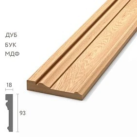
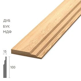
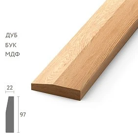
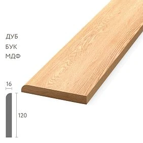
Composite ceiling cornice: one architectural solution, several procurement line items
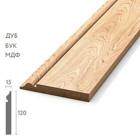
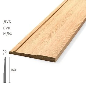
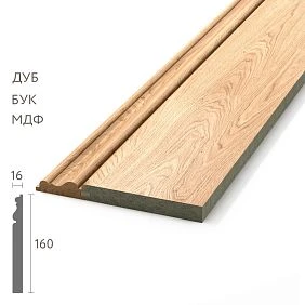
In a project visualization, a multi-layer upper molding looks like a single line. For example, three profiles run from the wall to the ceiling: a narrow lower molding forms the transition, a more massive middle profile sets the main relief, and the upper one closes the junction to the ceiling and completes the silhouette. For the designer, this may be "cornice SK-01." For the buyer, such a designation is useful only as a kit code, but it is not enough for ordering.
Each layer has its own identity. You cannot write "three profiles of one cornice" in a request if the exact line items are not fixed. Even products that look similar may have different cross-sections, different commercial lengths, be made from different materials, and require different finishes. On a long straight wall, their finished meters may indeed be almost identical, but near a box-out, built-in wardrobe, portal, column, or termination, one layer may continue farther than another. At that point, the total meterage stops working as a procurement unit.
Therefore, it is convenient to represent a composite molding on two levels.
The first level is the system. For example:
SK-01 — composite ceiling cornice for a standard room.
Second level — system composition:
| Layer | Function | Article | Material | Finish | Status |
|---|---|---|---|---|---|
| А | lower transition profile | According to the approved specification | As per project | O-01 | Approved |
| Б | main cornice | According to the approved specification | As per project | O-01 | Approved |
| В | upper finishing profile | According to the approved specification | As per project | O-01 | Approved |
There are deliberately no invented article numbers, dimensions, or materials here. They must be transferred from actually approved product cards and the working specification of a specific project. The point of the table is different: one code SK-01 links several products, but does not replace them.
For purchasing, this is a fundamental difference. If the estimate lists “composite cornice — 850 m,” this line does not make it possible to understand how many strips of each profile are needed. But if “SK-01 = A + B + C” is recorded, A, B, and C can be calculated separately, and then it can be checked whether each layer is sufficient for the required number of rooms.
That is why, when purchasing mouldings wholesale, all elements cannot simply be called a “cornice.” In an architectural description, such language is acceptable; in an order, it creates a risk of picking errors. For each profile, the exact product type, article number, material, cross-section, commercial length, and finish option must be specified. Only after that does the system become manageable.




SK-01 system passport: the document from which calculation begins
Before calculating quantities, it is useful to create a short passport of the composite assembly. This is not a design album or a supplier’s commercial proposal. The passport is needed so that all project participants understand in the same way what the upper cornice consists of and which revision is considered current.
The minimum passport includes:
-
system code, e.g. SK-01;
-
application area: type A number, corridor, hall, restaurant;
-
number of layers;
-
exact SKUs of all layers;
-
material of each profile;
-
full cross-section or reference to the approved working drawing;
-
commercial length of each SKU;
-
finishing;
-
relative position of the profiles;
-
overlap amount if the profiles overlap each other;
-
total height and total projection of the assembled system;
-
termination rules for a wardrobe, portal, niche and other boundaries;
-
code of the current revision.
The passport is needed because one of the most unpleasant mistakes occurs after the appearance has been approved. The architect replaces the upper molding with a lighter one, but the name of the set SK-01 in the general list remains the same. The purchaser opens the old table and orders the previous profile. Formally, the system code matches, but in fact the composition is already different.
To prevent this from happening, a change to any layer must change the revision. For example:
SK-01 / REV01 — the originally approved system.
SK-01 / REV02 — upper profile B changed.
The old revision is not deleted without a trace: it is kept in the archive, but only the current version goes into the order and the request to the supplier. For a large project, this is not bureaucracy, but protection against a situation where different floors are suddenly assembled with different combinations of profiles.
The passport also helps distinguish several similar systems. Standard numbers may use a two-layer rod SK-01, deluxe rooms may use a three-layer SK-02, and the lobby may use a more complex SK-03 made of four profiles. If all of them are called “ceiling cornice” in the estimate, mistakes are almost inevitable. System codes turn visually similar solutions into unambiguous sets.
To select the initial profiles, it is convenient to use the category of wooden cornices STAVROS, but transfer to the working specification not the general name, but the specific approved item. If you first need to sort out exactly the upper line of the interior, the material on Wooden ceiling skirting board. Further in the article we will use the designations A, B, and C so as not to attribute to specific products compatibility that must be confirmed by the project.
Our factory also produces:







Cross-section drawing 1:1: why photographs of profiles are not enough
A catalog photograph shows the appearance of an individual product, but does not answer the main question of a composite system: how the profiles work together. Therefore, before placing a wholesale order, a working section is needed on which the wall, ceiling, and all layers of the cornice are visible at the same time.
On the 1:1 section, the following should be recorded:
-
wall plane;
-
the ceiling plane;
-
the position of layer A;
-
the position of layer B;
-
the position of layer C;
-
attachment points or zones;
-
the amount of overlap of one profile over another;
-
overall projection of the system from the wall;
-
total height;
-
visible shadow gaps;
-
position of the finishing layers of the wall and ceiling.
Why is a 1:1 scale more useful than a beautiful visualization? Because in a composite molding, changing even one mutual offset alters the silhouette of the entire assembly. If the lower molding is raised higher, part of its relief may be hidden under the main cornice. If the main profile is pushed forward, the shadow and the length of the short returns change. If the upper layer is lowered, the overall height increases, and on a low ceiling the system begins to look heavy.
You must not independently increase or decrease the overlap "to make installation easier." If the architect has approved a specific stepped geometry, an installation shift turns the original composition into a different one. This is especially noticeable on external corners, where the eye sees all levels of the profile at once.
The section is needed not only by the installer. From it, the purchaser understands that three profiles identical in routing may have different actual lengths at the ends. The estimator sees why one linear meterage cannot be multiplied by three. The supplier gets a clear link between the article number and the layer of the system. The receiver can compare the delivered items with what is actually required for assembly.
If there are several systems in the project, each needs its own section. One should not assume that SK-02 differs from SK-01 "only by one more molding." Adding a layer can change the overall height, projection, internal corner layout, assembly sequence, and length of the returns.
Get Consultation
Control mock-up: assemble the system before launching a large batch
Before ordering for dozens or hundreds of rooms, it is useful to manufacture and assemble a physical control mock-up. Checking three separate strips on a table is not enough. What is needed is precisely the assembly: a wall fragment, a ceiling fragment, and all layers of the composite cornice in their design position.
On such a sample, they check what is hard to read from the drawing:
-
the actual total height of the system;
-
actual projection;
-
the depth of shadows between the steps;
-
the readability of the relief from below;
-
the alignment of the profile lines;
-
the quality of the layer joints;
-
the chosen color and degree of gloss;
-
the behavior of the seams;
-
the visual scale relative to the room.
For a large series, the final check is especially important. A profile may look convincing in a large catalog image, but in a standard unit with a specific ceiling height, the three layers together will turn out to be too massive. Fixing this on a sample is inexpensive. Fixing it after production of the batch, painting, and delivery is significantly more difficult.
The control fragment should be considered part of the specification approval, not an optional decorative mockup. Until the sample is approved, the composition of the system formally remains open. After approval, the item codes, the geometry of the relative arrangement, and the finish are fixed. If at least one layer changes later, the sample or critical assembly should be checked again.
For a complex classical system, it is useful to make not only a straight fragment but also a test external corner. On a straight section, a small error in the height of one layer is sometimes almost unnoticeable. At an external corner, the steps converge at a single point, and any misalignment immediately becomes visible.
One profile — one independent calculation
The most dangerous arithmetic mistake looks logical: if a composite cornice consists of three profiles, take the total perimeter and multiply it by three. For a preliminary estimate of mass or a very rough budget, such a figure can give an order of magnitude. For ordering, it is unreliable.
The reason is that each layer has its own route. On a long straight wall, the routes do indeed coincide. But further on, there appear sections where the system ceases to be geometrically identical across layers:
-
one profile ends at built-in furniture, another passes above it;
-
the upper layer goes around a ceiling box, the lower one ends earlier;
-
one profile has a short return, the other does not;
-
the projections of the layers differ, so the lengths of the returns at the ends do not match;
-
at an external corner, the cut lines differ because of the cross-section;
-
in one room, part of the molding is replaced by another unit.
Therefore, a separate bill of materials is created for each SKU. First, layer A is calculated, then B, then C. Only after that can they be combined into set SK-01.
The worksheet might look like this:
| Room | System | Layer | Article | Clean parts | Product length | Cutting planks | Reserve | Total to order |
|---|---|---|---|---|---|---|---|---|
| Number A-01 | SK-01 | А | Per specification | by part map | By card | Calculation | Calculation | Calculation |
| Number A-01 | SK-01 | Б | Per specification | by part map | By card | Calculation | Calculation | Calculation |
| Number A-01 | SK-01 | В | Per specification | by part map | By card | Calculation | Calculation | Calculation |
The "net parts" column is more important than a single meterage figure. It shows which segments actually need to be obtained after cutting. Two layers may have the same 18 meters of requirement but require a different number of commercial planks if one consists of long straight parts and the other of many short segments that do not fit well into the standard length.
This is the case when the math by linear meters says "there is enough material," but the actual cutting requires one or more additional whole planks.
Straight walls: when layer meterages match, and when consumption diverges
On an ordinary straight wall, the calculation begins with the net length of each layer. If all three profiles start and end in the same vertical plane, their net lengths will be close or identical. But this must be established from the drawing, not assumed.
For example, a wall section 5,200 mm long may have three identical lines A, B, and C. This does not yet mean that all layers will require the same number of planks. If the commercial lengths differ, the number of joints and the number of whole pieces will be different.
Let's assume this is a conditional calculation, not a characteristic of specific products:
-
layer A is supplied conditionally in 2,400 mm lengths;
-
layer B — in 2,000 mm lengths;
-
layer C — in 2,600 mm lengths.
For a single straight line of 5,200 mm, the minimum logic already differs:
-
A: 2,400 + 2,400 + 400 — three planks;
-
B: 2,000 + 2,000 + 1,200 — three planks;
-
C: 2,600 + 2,600 — two planks.
But this is not yet the final cutting plan: the remaining parts can be used on adjacent walls, returns, or in another room. Therefore, each wall cannot be considered in isolation if the project allows centralized cutting and transfer of usable offcuts.
Layer lengths begin to diverge even before cutting, when an architectural constraint appears nearby. Imagine a built-in wardrobe up to the ceiling. The lower transition molding may terminate at the side panel of the wardrobe, the main cornice may reach it with a separate termination, and the upper profile may continue along the ceiling line above the wardrobe. On the plan this is one section, in the bill of materials it is three different routes.
A ceiling box works similarly. The upper layer often follows the ceiling geometry, while the lower layer may have a shorter path. If they are combined under a single linear meterage, the discrepancy will only be discovered during installation.
Internal and external corners: one room corner — multiple system junctions
The ordinary phrase "a room has four corners" hides an important detail. For a three-layer cornice, each internal corner is three separate junctions. One hundred identical rooms with four internal corners yield not just 400 corners, but up to 1,200 corner joints across the layers.
This does not mean you need to buy "1,200 corners" as separate parts — the method of forming a corner depends on the specific profile and technology. The point is different: labor intensity, risk of error, and cutting requirements increase for each layer separately.
For serial rooms, it is convenient to assign codes to typical junctions. For example:
IC-SK01 — internal corner of the SK-01 system.
In the working album, a diagram of all layers is linked to this code. The installer does not reinterpret each corner anew, but repeats the approved solution.
External corners require even more attention. The stepped structure of the system is simultaneously visible on them. If one profile is shifted, has a different height, or is cut incorrectly, the error is more noticeable than on a straight wall. Therefore, for a complex system, it is reasonable to pre-assemble a trial external corner and record the order of cutting and joining.
When calculating external corners, one cannot automatically assume the length of all returns is the same. The layers have different projections from the wall. If the end of the system must return to the plane, the length of this short section is determined by the actual geometry of the specific layer. The upper profile may require one return, the main one another, and the lower one a third.
For the purchaser, short parts are dangerous because they seem like a "trifle". In meters there are few of them, but they are the very things capable of worsening the cutting layout. A long strip, after cutting two short returns, may leave a remainder that is not suitable for long walls. Therefore short elements must be present in the parts map before determining the number of strips, and not added after calculating the total linear meters.
Boxes, protrusions and niches: a small element that sharply increases the number of parts
A ceiling box one to one and a half meters long seems insignificant against the backdrop of hundreds of linear meters of trim. For a three-layer system, it can turn out to be one of the most part-dense sections.
One box can add:
-
short straight fragments of each layer;
-
internal corners;
-
external corners;
-
side returns;
-
separate ends;
-
additional joints.
If the box is repeated in every hotel room, the small local complexity scales to the entire project. Therefore repeating architectural elements should be separated into individual modules.
For example:
KB-01 / SK-01 — a set of profiles of the SK-01 system for a ceiling box of type 01.
First, the KB-01 module is calculated in full: which parts belong to layer A, which to layer B, which to C. Then the cutting layout is checked. After approval, the same module can be replicated according to the number of rooms, if the geometry is truly identical.
This is far more reliable than adding "roughly a metre per box" anew in every room. That approach loses corners, returns and the difference between layers. As a result, the total metreage may look sufficient, but the required short pieces cannot be made from the available offcuts.
Niches and projections should be counted using the same logic. If an architectural element repeats, it is worth giving it a code. If it is unique, it should be left as a separate line rather than dissolved into the average consumption per room.
Endings: where and how the whole system should terminate
A composite cornice may end at a wardrobe, a door portal, a column, a window, a decorative panel or a transition into another zone. The weakest scheme is simply to cut three profiles in different places however it turned out on site.
The ending must be designed as a junction. For each layer, you need to answer:
-
where the last visible point runs;
-
which profile ends first;
-
whether the end face should be closed with a return;
-
whether on-site trimming is required;
-
whether the cross-section remains visible;
-
whether the line should align with the vertical of the adjacent element;
-
whether there is a constraint from furniture or engineering equipment.
Random steps look especially bad when the lower profile ends at one level, the main one protrudes a few more centimeters, and the upper one is cut along a different line. Sometimes a stepped ending is genuinely intended by the architect, but then it should be fixed on the drawing, not arise from a shortage of material.
Endings also affect purchasing. A layer with a larger overhang may have a longer return. Another layer may have a separate short blanking piece. Therefore, the general phrase "add 100 mm to the end" does not replace calculation based on geometry.
For serial rooms, it is useful to have one approved ending detail and repeat it. If the endings in left and right rooms are mirrored, it is better to label them separately: for example, ОК-СК01-Л and ОК-СК01-П. This reduces the risk that pre-cut or prepared elements end up in the wrong room.
Typical room: first one complete set, then scaling
On a project with a large number of identical rooms, it is tempting to immediately multiply the perimeter of one room by 80 or 100. It is more correct to first fully complete one reference room as a mini-project.
For it, you need to obtain:
-
a map of all sections of the СК-01 system;
-
a list of parts for layer A;
-
list of layer B parts;
-
list of layer C parts;
-
cutting map for each SKU;
-
number of commercial strips;
-
list of usable remnants;
-
set of corners, returns, and end caps;
-
packaging labeling;
-
final set for one number.
After that, the purchasing unit appears:
SK-01 / type A number — one complete set.
Only now is scaling allowed:
SK-01 / type number A × 80.
Why can't you simply take the total perimeter of the room, multiply by three layers, and then by 80? Because such multiplication preserves only the total linear meters. It does not preserve the structure of the parts. Short returns, differences in end treatments, different commercial lengths, and the possibility of using the remainder of one section on another all disappear.
For serial purchasing, not only the total volume matters but also the repeatability of the set. If one number is calculated correctly, it can be turned into a standard. If the original number is calculated roughly, the error scales as well — and instead of one missing plank, you get a shortage for an entire floor.
Mirrored numbers: the same volume does not mean the same layout
A left and right hotel room may have the same perimeter and the same profile composition. The purchasing volume may indeed match. But the parts map will be mirrored.
This is especially important if some elements are cut, labeled, or grouped by room in advance. A part prepared for the left end may not fit the right assembly without reworking.
Convenient marking:
-
SK-01L — left variant;
-
SK-01R — right variant.
At the purchasing level, identical planks can be combined into a common volume if this does not hinder control. At the kitting level, the link to the room must not be lost. Otherwise, the warehouse receives “800 identical meters,” and the crew on the floor wastes time sorting and re-cutting.
If the project allows centralized cutting, mirrored numbers can be optimized together: use the remainder from the left set in the right one, if the material, article, finish, and required length match. But such a decision must follow from the cutting map, not from the assumption that any offcuts will be useful somewhere else.
Suites, halls and corridors: different routes — different systems
A standard room cannot be "stretched by a coefficient" into a suite. Even if the suite's area is one and a half times larger, the cornice route may differ fundamentally: more niches, columns, breaks, panoramic windows, bulkheads, built-in furniture. Therefore, a separate system is created for it, for example SK-02.
A hall may use a more complex composition. In rooms — two or three layers, in the front zone — four. If you simply add a fourth profile to the general schedule, it becomes unclear where it is actually needed. It is better to record:
-
SK-01 — room stock;
-
SK-02 — suites;
-
SK-03 — hall;
-
SK-04 — restaurant or another separate zone.
Corridors differ from rooms even more. Instead of short repeating spaces, long straight lines appear. Here the economics of cutting change. A long commercial bar may produce fewer joints, but this does not automatically make it the best choice: you need to consider the actual length of the walls, the requirements for joint placement and the possibility of delivery to the floor.
In addition, each layer may have its own commercial length and its own price. Therefore, a corridor cannot be treated as a single line "cornice — 180 m". Separate maps are needed for A, B and C. On one layer, offcuts may conveniently go into short sections at door portals, while on another they may remain useless.
If a project simultaneously includes rooms, corridors and halls, the master specification must preserve the separation by systems. This allows you to see not only how much material is needed in total, but also which profile is critical for a specific zone.
Material and finish: a product code without a configuration may be an incomplete line
With a composite cornice, it is risky to assume that one product code always means the same purchasing parameter. Specific product items may have variants in material, length, or finish. Therefore, the working schedule should carry not only the product code but also the configuration approved for the project.
If layer A is made of one material and layer B is made of another, these are two independent items, even if they are painted the same color and visually perceived as a single molding. They cannot be combined under a shared reserve. Processing behavior, available stock lengths, weight, price, and lead times may differ.
A rigorous specification records for each layer:
-
article number;
-
exact name;
-
material;
-
section dimensions;
-
product length;
-
surface preparation type;
-
finishing;
-
code of the approved color sample, if used;
-
quantity of whole items.
If the designer wrote only "oak molding, white enamel," the supplier still does not know which profile is required. If only a product code is specified but it has multiple versions, the line can also be ambiguous. The goal is to ensure that a different variant cannot be selected from a single line without explicit approval.
To verify current configurations, refer to the active product page for the specific item at the time of ordering. Do not carry over length, material, or price from an old article, a previous estimate, or a saved screenshot if the product page has changed. A wholesale specification must be based on current product information and the approved project.
Product length and cutting map: why total linear meters do not equal the number of strips
Linear meters show the requirement, but delivery is made in specific product items. To convert net linear meters into quantity, a cutting plan is needed.
A separate map is built for each layer:
-
map A;
-
map B;
-
map C.
They cannot be mixed: the remainder of profile A does not physically replace profile B, even if the length fits perfectly. In the depersonalized line “cornice — 1,200 m,” this obvious fact disappears, and the purchaser sees only the total figure.
The best order for distributing parts within one SKU is usually as follows: first the longest and most critical segments, then long straight sections, after them medium parts, short returns, and small fillers. This is not a universal algorithm for any production line, but it is a useful principle for manual checking: a long part cannot be assembled from two short remainders without a joint, while a short return can often be obtained from the remainder after a long section.
An example where linear meters deceive
Let us take a conventional profile A with a length of 2.4 m. This is a training assumption, not a characteristic of a specific product. For one module, the following parts are needed:
-
four pieces of 2.35 m each;
-
four pieces of 1.30 m each.
Net length:
4 × 2.35 + 4 × 1.30 = 14.60 m.
If you divide only the meters:
14,60 / 2,40 = 6,08.
Rounding up gives seven boards, that is 16.8 m. It seems there is enough material.
But four pieces of 2.35 m already take up four separate boards. The remainder of each is only 0.05 m. Four pieces of 1.30 m cannot fit two per 2.40 m board because:
1.30 + 1.30 = 2.60 m.
This means each of the four 1.30 m pieces requires its own board or another compatible remainder, which is not available in this layout. In total, eight boards are needed, not seven.
Purchase length:
8 × 2.40 = 19.20 m.
Difference between net requirement and purchase:
19.20 − 14.60 = 4.60 m.
This is not a "31.5% reserve" in the usual sense. A significant part of the difference arose from the cutting geometry. If you simply add the standard 10% to 14.60 m, you get 16.06 m — still less than the required 19.20 m.
This is exactly why the rule "total linear meters plus ten percent" does not work as a universal formula.
Why another layer with a similar linear meterage can be laid out better
Let a conventional profile B of the same commercial length of 2.4 m require:
-
four parts of 2.10 m each;
-
four parts of 0.30 m each.
Each long part of 2.10 m can be combined with a short part of 0.30 m:
2.10 + 0.30 = 2.40 m.
The entire set fits into four planks with no remainder. Two layers of the same system have a similar total route, but a completely different material utilization rate.
This difference explains why the reserve must be calculated separately for each SKU.
Reserve: not a general percentage per system, but protection of the critical layer
The entry "composite cornice + 10%" looks convenient for an estimate, but it manages the actual order poorly. Each profile has its own cutting plan, its own risks, and its own opportunity to use offcuts.
The reserve for layer A is calculated separately from B and C. The final specification must clearly show:
requirement A + reserve A;
requirement B + reserve B;
requirement C + reserve C.
Why is this especially important for multilayer traction? Because the system is finished only when all its layers are finished. If 40 meters of profile A and 25 meters of profile B remain on site, but profile C has run out, these leftovers do not allow completing even one new section of SK-01.
The reserve must take into account the cause of the risk. Different situations are possible:
-
complex cutting with a large number of short pieces;
-
risk of damage during transport or installation;
-
the need to keep some material as an operational reserve;
-
a remote site where an urgent reorder is especially inconvenient;
-
a long time gap between the first and last phases;
-
a unique finish that is best kept within a single consistent batch.
But the reserve must not turn into an arbitrary percentage "just in case." First, the cutting plan is built and the required number of full planks is determined. Then a deliberate safety reserve is added separately, if needed.
For repeating rooms, it is useful to keep the reserve not only in meters, but also in clear units. For example: "two full SK-01 sets for a standard room" or "N full planks of layer B." This format helps clarify exactly what can be restored in case of damage.
Cost: you should compare not a single profile, but the linear meter of the finished system
In a composite cornice, the price of the main profile does not show the cost of the architectural solution. If layer B is expensive, but A and V are cheap, the overall budget may be acceptable. And vice versa: an inexpensive main cornice does not make the system cheap if two additional moldings, a complex finish, and high waste sharply increase the total.
To compare options, it is useful to calculate the cost per linear meter of the finished system, but only after calculating the actual quantity of all elements.
The cost of SK-01 includes:
-
profile A;
-
profile B;
-
profile C;
-
the actual number of whole strips according to the cutting plan;
-
unusable offcuts;
-
the selected processing and finish;
-
packaging, if it is calculated separately;
-
logistics;
-
additional operations, if they are included in the specific quote.
The formula for a project might look like this:
Cost of SK-01 = cost of A + cost of B + cost of C + agreed additional expenses.
Next:
Price per linear meter of the finished system = total procurement cost of SK-01 / actual length of the installed system.
But even this figure should not be used in isolation from the configuration. Two systems with the same price per installed meter may differ in the number of joints, the reserve, installation complexity, and ease of repeat procurement.
When comparing commercial proposals, it is important to bring them to a single closed specification. The same principle applies when comparing building materials at wholesale prices: first a comparable configuration, then price. You cannot compare a "cornice at 900 ₽/m" from one supplier with a "system of three profiles at 2,400 ₽/m" from another. First you need to make sure that the composition, material, cross-section, lengths, finish, and volume are equivalent in meaning.
How to assemble the system in the warehouse and on site
Even a perfectly calculated procurement can lose its meaning in the warehouse if the three layers arrive and are stored as independent items without any connection to the system.
It is not necessary to physically pack A, B, and C into one bundle. For long-length linear moldings this may be inconvenient. But the labeling must preserve the logic:
-
SK-01-A;
-
SK-01-B;
-
SK-01-V.
Additionally, specify the room type, floor, or installation phase if required by the project logistics.
Why is the system code needed next to the SKU? The SKU answers the question "what is this product?" The SK-01 code answers the question "which architectural set does it belong to?" Both answers are needed by the installer and the kit assembler.
If there are ten different moldings and cornices in the warehouse, an experienced specialist may still figure it out using SKUs alone. But in serial kitting, the task must be resilient to staff turnover. A new employee should not have to guess from a photo which three items form the upper trim of a type A unit.
A useful batch labeling scheme:
Object → zone → system → layer → SKU → material → revision → quantity.
For example, without specifying the actual
Delivery of finishing materials by phases must preserve the completeness of the system, rather than simply dividing the total linear meters evenly between trucks.
Key rule: the delivery phase must be complete by system.
If SK-01 is planned for installation on floors 2–3, layers A, B, and C must be delivered there in quantities sufficient for the agreed number of rooms. A poor plan is to first bring all the lower molding to the site, then the main cornice two weeks later, and the upper profile another month after that, if installation is performed as a single assembly.
This kind of logistics creates several problems:
-
the warehouse fills up with material that cannot yet be used;
-
the risk of damage during handling increases;
-
it is difficult to determine the readiness of a specific area;
-
installers begin partially assembling the system and return to the same rooms later;
-
packing errors are discovered with a delay.
It is better to split the order by installation phases, keeping a complete set of layers within each phase. For projects in Moscow, this same task is covered in detail through finishing materials wholesale moscow — not as a one-time unloading of the entire volume, but as a managed series of deliveries. For example:
Phase 1 — floors 2–3: complete SK-01 set.
Queue 2 — floors 4–5: complete SK-01 set.
Queue 3 — hall: SK-03 system.
At the same time, all queues must reference a single master specification. You cannot create a separate independent file for each floor and manually change the quantity in it. Otherwise, after the first adjustment, profile A will be updated in one file while the others remain outdated.
Changing one layer: why a local replacement requires checking the entire system
Sometimes a designer changes only the top molding. It seems that only one line needs to be recalculated. In fact, the new profile affects at least several parameters:
-
removal;
-
total height;
-
overlap with the adjacent layer;
-
length of short returns;
-
layout of internal and external corners;
-
endings;
-
product length;
-
cutting map;
-
cost;
-
weight and packing method, if the difference is significant for logistics.
This does not mean that the entire system must be calculated from scratch. The correct procedure is to replace the layer locally and run a dependency check.
For example, profile B in REV01 is replaced with another one in REV02. Then:
-
the SK-01 data sheet is updated;
-
the 1:1 section is checked;
-
if necessary, the physical sample is updated;
-
the layer B bill of materials is recalculated;
-
the joints where B affects A or C are checked;
-
the cutting list for B is recalculated;
-
the system cost is updated;
-
the new revision is passed to the buyer and the supplier.
An old quotation cannot be carried over to a new version without checking. Even if the number of meters has barely changed, the commercial length of the new profile may change the number of bars.
Practical calculation: 100 identical rooms and three independent cutting plans
Let's consider a training model. All numbers below are conditional data to demonstrate the method, not parameters of specific STAVROS products.
A typical room uses the SK-01 system of three layers: A, B, and C. After measurements and breaking down the route by parts, the following sets were obtained.
Layer A
Commercial length is conditionally 2.4 m.
One room requires:
-
4 parts of 2.35 m each;
-
4 parts of 1.30 m each.
As shown above, by total meters it seems that seven planks are enough, but the actual cutting requires eight.
For 100 rooms without additional inter-room optimization:
8 × 100 = 800 planks.
This is the reference upper model. Before ordering, you can check whether the leftovers between numbers can be used and the quantity reduced. But the reduction must be confirmed by the overall cutting map, not by assumption.
Layer B
Commercial length is conditionally 2.4 m.
One room requires:
-
4 parts of 2.10 m;
-
4 parts of 0.30 m.
Each pair of 2.10 + 0.30 fills the plank completely. Four planks are needed per number.
For 100 numbers:
4 × 100 = 400 planks.
Layer C
Let the nominal product length be conditionally 2.6 m.
One room requires:
-
4 pieces of 2.50 m each;
-
4 pieces of 1.20 m each.
Four pieces of 2.50 m require four planks. Pieces of 1.20 m can be placed two per plank:
1.20 + 1.20 = 2.40 m.
For four short pieces, two more planks are needed. Total six per number.
For 100 numbers:
6 × 100 = 600 planks.
Now it is clear how useless the general entry “three profiles per 100 numbers” is. Each layer has a different number of product units and a different share of the remainder.
Summary table of the training example:
| Layer | Nominal plank length | Planks per room | Numbers | Base quantity |
|---|---|---|---|---|
| А | 2.4 m | 8 | 100 | 800 |
| Б | 2.4 m | 4 | 100 | 400 |
| В | 2.6 m | 6 | 100 | 600 |
After this, it is not an abstract "reserve for the entire curtain rail" that is added, but a separate reserve for each layer, calculated according to the project rules.
What happens if a hall is added
Suppose the hall uses the SK-02 system: A + B + C + D. You cannot simply add the meters of profile D to the general SK-01 schedule. The hall has a different route, a different set of angles, and its own cutting map. SK-02 is calculated separately and only then included in the overall master specification of the project.
This approach allows you to answer a specific question at any time: how many complete SK-01 kits can be assembled, how many SK-02 are ready for installation, and which layer is limiting progress.
How to organize a master specification for a large project
For wholesale purchasing, it is convenient to keep one main document from which supplier requests, floor kits, and acceptance schedules are generated. Its task is not to replace working drawings, but to link the project with purchasing.
Minimum structure:
| Field | What to fix |
|---|---|
| System code | SK-01, SK-02, SK-03 |
| revision | Current version |
| Zone | room, corridor, hall, restaurant |
| Room type | A, B, deluxe, etc. |
| Layer | A, B, C, D |
| Article number | exact product position |
| Material | According to the approved execution |
| Cross-section | by card/drawing |
| commercial length | relevant for the selected variant |
| Clean parts | link to parts map |
| Strips by cutting plan | cutting result |
| Reserve | separately by position |
| TOTAL | whole number of items |
| Installation sequence | delivery stage |
| Status | calculated / approved / ordered / accepted |
Wholesale purchasing of building materials becomes manageable only when the master specification remains the single source of quantity and revisions.
This table should not turn into an endless file where identical rows are copied manually. For typical rooms, a quantity coefficient can be used after one set has been calculated and approved. But the original card of a single number must be preserved so that it is clear where the number came from.
In the master specification, it is useful to distinguish between net requirement and purchasing quantity. If responsibility needs to be established between the customer, contractor, and kit assembler, this part should be linked to the rules wholesale purchasing of building materials. Net footage answers the question “how much of the system will be installed.” Purchasing quantity answers the question “how many whole product items need to be received.” Cutting is always between them.
Supplier and manufacturer: what data to transmit for calculation
When it is necessary to buy ceiling skirting in bulk or assemble a composite cornice from several profiles, the request to the supplier must be specific enough so that the response is not based on guesswork. For the general procedure wholesale purchases of building materials it is useful to separate internal approval and the actual order to the supplier.
Wholesale purchases of building materials at such a site are easier to handle when the supplier receives an already approved set of input data rather than a request to "estimate roughly."
It is worth providing:
-
system code and revision;
-
list of exact SKUs;
-
material and finish for each;
-
required commercial lengths, if they are part of the selection;
-
quantity of whole items per each layer;
-
desired finish;
-
breakdown by installation phases;
-
delivery address and terms;
-
timelines;
-
substitution approval rule.
finishing material suppliers they can offer an alternative if the original item is not available, but the alternative line must not imperceptibly replace the approved one. For a multi-layer cornice, "almost the same profile" is especially risky: it may not match in height, projection, or the way it interfaces with adjacent layers. Therefore, when working with wholesale building material suppliers critical parameters must be fixed in the specification before requesting a price.
If purchasing directly from the manufacturer, it is useful to separately agree on consistency of execution between batches, especially when delivery is spread over months. For a broader scenario, you can separately check the material on building materials wholesale from the manufacturer. But one should not assume that the word "manufacturer" by itself automatically guarantees any length, material, or lead time. The capabilities of a specific item are confirmed against the current product range and commercial offer.
A controlled process is important for the project: first the approved system, then an unambiguous request, after that an offer based on the same specification, then the order, production/packing, marking, delivery, and acceptance.
When a composite cornice does not need to be complicated
A multi-layer cornice is not justified in every room. If the architectural task can be solved with one profile, adding a second and third solely for visual complexity is not always rational.
A composite system should be abandoned or simplified if:
-
the ceiling is low and the total height of the profiles visually overloads the room;
-
the space is minimalist and complex relief contradicts the overall architecture;
-
there is no way to assemble and replicate complex angles with quality;
-
the project is not ready to lock in the exact geometry before procurement;
-
the finish will often be dismantled or upgraded;
-
the budget is sensitive not only to the price of profiles, but also to the labor intensity of installation;
-
the site is too small for the advantages of serial kit configuration to matter.
Sometimes one expressive wooden ceiling cornice is better than three poorly coordinated moldings. This article does not aim to prove that a multilayer system is always better. Its task is to show how to properly calculate such a system if it is already justified by the project's architecture.
Mistakes that turn multilayer molding into constant reorders
1. Ordering a composite cornice as a single line item
Why it happens: the estimate describes the architectural result, not the actual product items.
Consequence: the supplier and the purchaser interpret the composition differently, and completeness cannot be verified.
How to prevent: system code plus separate lines for all layers.
2. Do not lock in the exact system composition
Why it happens: the combination of profiles is considered obvious after the visualization is approved.
Consequence: when replacing or reordering, a different profile ends up in the system.
How to prevent: SK-01 passport with item codes, materials, finish, and revision.
3. Calling all elements a “cornice”
Why it happens: colloquial language carries over into the procurement table.
Consequence: mis-sorting and ambiguous requests.
How to prevent: keep the actual product type and item code for each layer.
4. Do not make a 1:1 section
Why it happens: it seems that catalog images are enough.
Consequence: incorrect overlap, height, projection, and endings.
How to prevent: approve the working section before launching the batch.
5. Not assembling a control sample
Why it happens: they want to move to purchasing faster.
Consequence: a mismatch in scale and junctions is discovered after producing a large volume.
How to prevent: assemble a physical fragment of the wall and ceiling with all layers.
6. Multiplying the total footage by the number of profiles
Why it happens: on straight walls, the layers really are similar in length.
Consequence: different endings, returns, boxes, and commercial lengths are lost.
How to prevent: a separate bill of materials for each article.
7. Count an internal corner as a single node regardless of the number of layers
Why it happens: they calculate the geometry of the room, not the number of junctions.
Consequence: underestimation of labor intensity and cutting errors.
How to prevent: consider the corner for each layer of the system.
8. Treat all returns as identical
Why it happens: different offsets of the profiles are ignored.
Consequence: short parts do not match in geometry.
How to prevent: take the dimensions of the returns from the working section.
9. Assume the same commercial length for all profiles
Why it happens: the items are visually perceived as a single set.
Consequence: incorrect number of planks and joints.
How to prevent: check the current length of each selected variant.
10. Create a single common cutting plan
Why it happens: all layers are combined under the line “cornice”.
Consequence: leftovers of one SKU mistakenly reduce the requirement for another.
How to prevent: separate plans A, B, C, and only then the overall set.
11. Add one percent reserve to the entire system
Why it happens: it is easier to calculate the estimate this way.
Consequence: one layer has an excessive reserve, while another lacks material.
How to prevent: keep a reserve for each item after cutting.
12. Do not label the layers of one system
Why it happens: they assume there are enough SKUs.
Consequence: the warehouse and installers lose the connection between items.
How to prevent: code SK-01-A, SK-01-B, SK-01-C next to the SKU.
13. Accept a batch only by individual SKUs
Why it happens: accounting acceptance ends with the quantity of each item.
Consequence: formally two items are closed, but there are fewer complete kits for installation.
How to prevent: count how many systems can be assembled from the accepted batch.
14. Change one profile without checking the joints
Why it happens: they consider the replacement to be local.
Consequence: the offset, height, angles, and endings change.
How to prevent it: release a new revision and check dependent components.
15. Sending the old revision to the supplier
Why it happens: files are named “final,” “final2,” “new final.”
Consequence: the order is placed using an outdated composition.
How to prevent it: a unified revision system and one active file.
16. Calculating the cost only by the main cornice
Why it happens: the middle profile visually dominates and seems to be the main one.
Consequence: the system budget is underestimated.
How to prevent: calculate the cost of all layers, cutting, and agreed additional costs.
17. Deliver layers at different times without connection to the installation sequence
Why it occurs: logistics are optimized for the convenience of individual items.
Consequence: the floor is filled with material, but the system cannot be assembled.
How to prevent: form the delivery stage as a complete system kit.
Final checklist before wholesale ordering
Before placing an order for wholesale ceiling skirting and composite cornice, check that unambiguous answers have been obtained for each system.
System and geometry
-
assigned code SK-01, SK-02, etc.;
-
the number of layers has been determined;
-
working section 1:1 approved;
-
overall height fixed;
-
overall projection fixed;
-
overlaps approved;
-
physical sample checked;
-
if necessary, a test external corner was assembled.
Product items
-
exact type of each product specified;
-
item code specified;
-
material fixed;
-
section fixed;
-
commercial length verified;
-
finish approved;
-
all rows have a single active revision.
Calculation
-
straight sections laid out by layers;
-
internal corners accounted for per layer;
-
external corners checked;
-
boxes allocated to modules;
-
returns calculated based on actual offset;
-
endings have a separate node;
-
the standard room is fully calculated before scaling;
-
left and right variants are distinguished if needed;
-
suites, corridors, and lobbies are not mixed with the standard room.
Cutting and Reserve
-
each SKU has a separate cutting map;
-
long critical parts are distributed first;
-
usable remnants have a clear purpose;
-
the reserve is calculated separately for each layer;
-
the final quantity is expressed in whole finished products.
Logistics and receiving
-
installation phases are defined;
-
each phase receives a complete set of layers;
-
there is labeling “system + layer + SKU”;
-
receiving checks both individual items and the number of complete sets;
-
disputed items do not go into installation until approval;
-
the master specification stores the total requirement for the project.
If even one of these points remains “approximate,” it is too early to turn the list into an order. The larger the series, the more expensive ambiguity becomes.
How to order a composite ceiling cornice wholesale without losing the project logic
It makes sense to order a ceiling cornice wholesale from the manufacturer after the architectural system has been translated from a visual concept into an exact procurement structure. For a single profile, a mistake can still be quickly corrected on site. For a three-layer molding, any inaccuracy multiplies: the wrong end piece is repeated across dozens of rooms, the wrong upper profile conflicts with the two adjacent ones, and the shortage of one layer halts the entire set.
The working sequence looks like this:
-
identify systems SK-01, SK-02 and others;
-
record the composition of each system;
-
check profiles on a 1:1 section;
-
assemble a control fragment;
-
approve the revision;
-
calculate one standard module for each article;
-
build separate cutting maps;
-
determine the reserve of each layer;
-
scale to the number of rooms;
-
add non-standard zones as separate systems;
-
create a master specification;
-
split the delivery by installation phases;
-
accept a batch by SKUs and by the number of complete sets.
If the system has already been selected, the next practical step is to verify the specific cornices, mouldings and other linear mouldings against the current product cards, transfer the exact designs into the specification, and only after that request a batch calculation. If the task starts from a broader category, the material on Wooden skirting boards wholesale helps separate a general B2B purchase from the calculation of a composite ceiling assembly specifically. For a broad selection of profiles, you can use the STAVROS wooden mouldings catalogue; for the upper zone — the category of wooden cornices and materials on choosing a wooden ceiling skirting. For large purchases, the rules for recording mouldings in the specification, phased delivery and comparing the total cost rather than just the price per linear metre are separately useful.
For search phrases such as "wooden ceiling skirting", "wooden ceiling skirting board", "cornices wholesale" or "mouldings wholesale", the purchasing logic remains the same: first the specific profile and its design, then the parts map, and only after that the quantity to order.
The main guideline remains unchanged: architecturally, a composite cornice may be a single element, but in purchasing terms it is always equal to the sum of its layers. If each layer is calculated, labelled, accepted and delivered as part of a specific system, a large run becomes manageable. If three profiles are dissolved into one line "cornice — N metres", the project begins to depend on guesswork, additional orders and manual error correction.
FAQ
Can a composite cornice be calculated using only the total perimeter of the rooms?
For a preliminary estimate — yes, for an order — no. The perimeter does not show the commercial lengths, angles, short returns, different ends and cutting of each profile. The final quantity is determined separately for each SKU.
If the system has three profiles of the same length along the wall, can you simply order the same linear metres of each?
The net linear meters may match, but the number of commercial strips does not. Profiles can have different commercial lengths and different cutting efficiency. Even with the same meters, one layer may require more whole units.
Is it mandatory to make a physical sample of the entire system?
For a simple two-layer solution on a small project, the decision is made by the design team. For complex traction that repeats dozens of times, a physical fragment sharply reduces the risk of scaling an error. A sample with an external corner is especially useful.
Can a general 10% reserve be used?
It can only be used as a preliminary estimate if this is accepted in the project. The final order is better calculated by the cutting layout of each SKU, and the safety reserve added after that. Some schemes require more than 10% due to the geometry of the parts, others less.
What should be done if one profile was replaced after calculation?
Issue a new revision of the system, check the cross-section and junctions, recalculate the map of this layer, check the angles and terminations, update the cost, and send only the current specification to the supplier.
Should the left and right type numbers be separated?
If only the mirroring differs, the total purchasing volume can be combined. But when marking and laying out parts, it is better to keep the left and right variants separate, especially if there are pre-prepared terminations or short elements.
How can you tell that the first batch is ready for installation?
Count not only the number of received strips, but also the number of complete systems. If out of three layers one arrived with only 12 pieces, the assembly readiness of the batch is 12 complete sets, even if the other two layers were received with 20.
What matters more: meters or pieces?
Both metrics are needed, but for ordering, the decisive factor is the number of whole products after cutting. Meters are convenient for monitoring overall demand, pieces — for actual delivery.
Can leftovers of different profiles be combined into a common reserve?
No. The leftover of one SKU does not replace another. The reserve is tracked for each position separately, and then it is assessed how many complete sets can be assembled from the available material.
When is it better to replace a composite cornice with a single profile?
When the multi-layer design provides no architectural value, overloads a low-ceiling room, makes installation too complicated, or exceeds the allowed budget. One correctly chosen cornice can be better than a system of three profiles if it exists only for the sake of complexity.