Article Contents:
- Why a wooden cornice must be coordinated not only with the ceiling architecture
- Commercial properties are especially sensitive to recurring conflicts
- Why cutting around a grille is not a neutral solution
- Diffusers and air distribution elements require the same spatial verification
- Why the decorative trim installer should not make this decision
- Why visualization is not enough
- Why a mirrored room requires a separate check
- When a break helps
- When a break makes the situation worse
- Long continuous sections are distributed first
- One relocated grille can change several parts at once
- Incorrect scenario
- Correct scenario
- Practical scenario: long curtain track runs next to service hatch in the lobby
- Practical scenario: new sensors added after architectural approval
- Practical scenario: engineering box splits one wall into three segments
- When engineering does not require changing the curtain track
- The final schedule must separate architectural gaps from engineering-driven ones
- The specification must have a version corresponding to the engineering revision
- Phased procurement allows ready areas not to be delayed due to a few complex assemblies
- The impact of engineering on SKU selection must be separated from its impact on quantity
- The SKU remains the same
- The architect specifies a different profile
- A critical engineering node must be checked before cutting the longest planks
- A post-installation check of the first phase improves the next coordination
- Before production, it is useful to compare design coordination with the actual upper zone
- What to record during such a reconciliation
- The production package must contain only closed decisions
- After coordination, it is necessary to check whether the commercial logic of the order has been lost
- 1. Calculating the curtain rod based only on the architectural plan
- 2. Checking only the ventilation
- 3. Looking only at the front view
- 4. Ignoring the curtain rod projection
- 5. Using the axis of the engineering element instead of the outer dimension
- 6. Moving the sensor or grille yourself
- 7. Reducing the curtain rod yourself
- 8. Cutting the curtain rod around the equipment "on site"
- 9. Do not check the hatch opening trajectory
- 10. Do not check the standard number before printing
- 11. Automatically transfer the solution to mirrored numbers
- 12. Do not split a long corridor into sections
- 13. Do not record the reason for the cornice ending
- 14. Recalculate the entire object because of one shifted element
- 15. Do not check adjacent segments when moving the grid
- 16. Build the cutting plan before closing engineering statuses
- 17. Consider the net footage equal to the purchased footage
- 18. Send the disputed version to the supplier
- 19. Checking only standard rooms and forgetting the halls
- 20. Trying to solve an engineering problem with a discount or extra material stock
- When to stop a wholesale order, even if the SKU and price have already been agreed
- Decision tree: what to do when an engineering element is found next to the cornice
- Is there an actual intersection on the plan or section?
- Does the conflict involve an engineering system?
- Is the cornice break approved?
- Does the detail repeat in standard rooms?
- Did the change affect only one wall?
- Bottom line: the curtain track must be coordinated with the actual engineered ceiling before purchase
- Final check before sending the order to the supplier
- Should the ventilation grille be relocated if it is close to the curtain track?
- Can we simply choose a smaller curtain track?
- Why make a section view if everything fits on the top plan?
- Should a single minimum distance from all sensors to the curtain track be specified?
- Can the curtain track be cut around a sprinkler or sensor?
- Why does the service hatch need to be checked separately?
- How do you check 100 identical hotel rooms?
- When should the final linear footage be calculated?
- Do we need to recalculate the entire object after moving a single grille?
- What should be sent to the supplier?

The architect approved a wooden interior cornice. The specification already includes the item code, material, finish, and preliminary linear footage. In the visualization, the ceiling line looks continuous. But before ordering, no one overlaid the cornice route onto the engineering ceiling plan. Already on site, it turns out that the same upper zone contains ventilation grilles, diffusers, sensors, fire protection system elements, service hatches, ceiling loudspeakers, and engineering ducts.
The problem arises not because the cornice is "wrong." It's simply that the architectural product and the engineering equipment were designed as two separate systems, while the actual space at the wall is one. A wooden cornice has height, depth, and projection. An engineering element also has actual dimensions, an installation zone, and, in some cases, a need for access. In a flat visualization they may not intersect, but in section they conflict.
Therefore, wholesale cornices from the manufacturer for a hotel, restaurant, office, or another complex object should be ordered only after spatial coordination of the upper junction.
Work sequence:
ARCHITECTURAL CEILING PLAN → ENGINEERING PLANS → WOODEN CORNICE ROUTE → POTENTIAL CONFLICT MAP → SECTIONS OF CRITICAL JUNCTIONS → APPROVED BREAKS AND TERMINATIONS → FINAL SCHEDULE OF SECTIONS → CUTTING → WHOLESALE ORDER.
Main principle:
THE PROCUREMENT SPECIALIST MUST NOT INDEPENDENTLY RELOCATE ENGINEERING SERVICES OR CHANGE THE ARCHITECTURAL PROFILE. THEIR TASK IS TO DETECT THE CONFLICT BEFORE PURCHASE AND OBTAIN AN APPROVED SOLUTION FROM THE RESPONSIBLE DESIGNERS.
Why a wooden cornice must be coordinated not only with the ceiling architecture
A standard architectural schedule answers the questions: which cornice, where the decorative line runs, what finish, and how many meters are preliminarily required. But it does not always show all the equipment that physically occupies the same ceiling zone.
Before the final order, at minimum the following must be overlaid on the cornice route:
- ventilation grilles and diffusers;
- sensors;
- fire protection system elements;
- lighting fixtures;
- service and inspection hatches;
- engineering ducts;
- loudspeakers and other ceiling devices in the project;
- areas where maintenance access is provided.
Not every adjacency is a conflict. The task of the check is not to force the entire ceiling to retreat from the decorative profile, but to identify places where two systems genuinely claim the same space or interfere with further maintenance.
If selected wooden cornice wholesale, its actual cross-section must be shown on the coordination section, not indicated with a conventional thin line.




Commercial facilities are especially sensitive to recurring conflicts
In a private room, a single complex junction can be refined on site for a long time. In a hotel, the same room is repeated dozens of times. In an office corridor, a decorative line can run for tens of meters. In a restaurant and lobby, ventilation, lighting, automation, and a decorative ceiling all operate simultaneously.
Therefore, the cost of an error grows not only because of the cost of the trim. One poorly thought-out point can be repeated:
- in 40–100 hotel rooms;
- along the entire long corridor;
- in several identical meeting rooms;
- in a series of public areas within one building;
- across several properties of the same chain.
If an already manufactured profile has to be locally trimmed around each engineering element, the project gets not one random defect, but a systematically recurring break in the architectural line.
That is why cornices wholesale for a serial interior, it needs to be coordinated on a typical room before launching the main batch.
Our factory also produces:
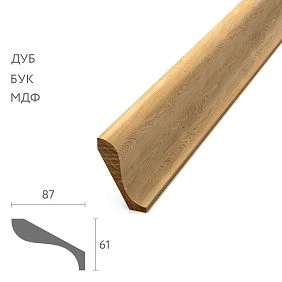
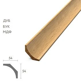
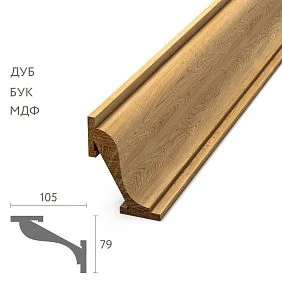
Verification requires a combined plan, not just an architectural elevation
The working basis looks like this:
ARCHITECTURAL CEILING PLAN + CURRENT ENGINEERING PLANS + CORNICE ROUTE.
On a single sheet or in a single coordination model, the actual boundaries of the products must be visible. If the information is stored in different sections, they still need to be reconciled before purchasing.
Minimum verification sequence:
- plot the curtain track route through the rooms;
- mark its actual cross-section and offset;
- overlay the engineering elements of the upper zone;
- identify potential intersections;
- create a section for disputed areas;
- assign a status to each node;
- close all statuses before the final batch calculation.
This approach is also important when working through Wholesale wooden trima single SKU by itself does not indicate that it is physically compatible with the engineering services already laid out.
Get Consultation
The conflict map separates a real problem from ordinary adjacency
| Room | Cornice section | Engineering element | What to Check | Status |
|---|---|---|---|---|
| Number 214 | Wall A | Ventilation grille | Actual boundaries and cornice projection | Requires coordination |
| 3rd floor corridor | K-17 | Sensor | Position relative to the decorative line | Check |
| Hall | K-04 | Service hatch | Access/opening trajectory | Requires cutting |
| Restaurant | K-21 | Engineering box | Cornice route and additional angles | Assembly approved |
The "check" status is more useful here than making an arbitrary decision. The kit assembler records a potential conflict but does not assign a new position for the ventilation grille, sensor, or other equipment.
Each row must have one of the following clear outcomes:
- no conflict;
- architectural assembly adjusted;
- engineering solution adjusted by the responsible section;
- the specified cornice gap has been approved;
- a separate end cap has been approved;
- re-check required after project revision.
The ventilation grille is checked by its actual dimensions, not by a nominal axis
On an engineering plan, an element may be shown by its center, mounting hole, or a nominal rectangle. For coordination with a decorative profile, this is sometimes insufficient.
Required:
- actual position;
- visible external dimensions after installation;
- distance from the wall;
- distance from the ceiling plane;
- access requirement;
- the space occupied by the cornice itself.
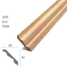
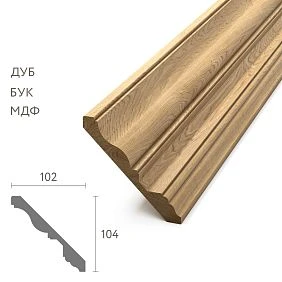
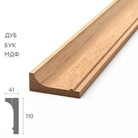
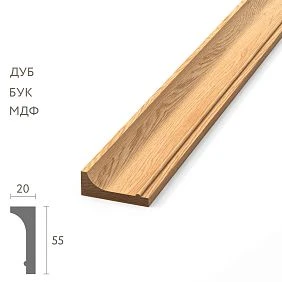
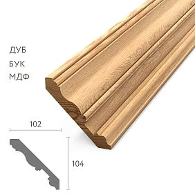
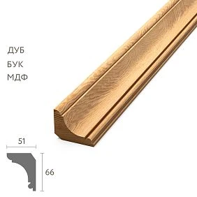
For example, the compact KZ-006 has a cross-section of about 55×20 mm for solid wood and 55×22 mm for MDF, whereas the KZ-013 measures approximately 90×90 mm. Two such profiles on the same plan line occupy completely different volumes. Therefore, a small cornice can pass next to an engineering element without conflict, while a deep one cannot.
You need to compare the actual boundaries of two objects in space, not the centers of their symbols.
Why cutting around a grille is not a neutral solution
A local cutout changes the architectural line and can create two open ends instead of one continuous section. If such a detail is repeated in dozens of rooms, it must be approved as a standard, not appear accidentally during installation.
Diffusers and air distribution elements require the same spatial check
For coordination, what matters is the external visible element after installation, not just the size of the duct or the opening above the ceiling.
It is necessary to understand:
- what actual area the device occupies;
- how far it is from the wall;
- whether it intersects with the cornice projection;
- whether the access specified in the design is required for it;
- does the decorative profile affect the visual composition of the ceiling?
This article deliberately does not specify universal distances. They depend on the specific engineering system, design requirements, and equipment documentation. The procurement task is to ensure that the conflict is resolved by the responsible designers before production of the wooden batch.
Sensors and automation must be marked on the cornice route before production of the batch
A small sensor may seem insignificant compared to a large decorative profile. But if its position coincides with the upper line of the cornice, the installation crew suddenly gets a choice it should not have: interrupt the decor, change the position of the device, or improvise with a local bypass.
The correct process:
IDENTIFIED A POTENTIAL INTERSECTION → RECORDED IT ON THE PLAN → SENT IT FOR COORDINATION → RECEIVED AN APPROVED DETAIL → ONLY AFTER THAT FIXED THE CORNICE ROUTE.
The procurement specialist must not independently assign a new sensor position. They also must not reduce the approved decorative profile without an architectural decision.
For a typical project, it is useful to introduce conditional statuses:
- NO CONFLICT — the engineering element and the cornice are spatially compatible;
- REQUIRES A SECTION — the top view is insufficient;
- REQUIRES AN ENGINEER'S SOLUTION — an engineering system is potentially affected;
- REQUIRES ARCHITECT'S DECISION — the decorative route or profile is changing;
- NODE APPROVED — can be included in the final schedule.
This discipline is especially important when, through Wholesale building material suppliers a serial delivery is already being arranged: an unresolved status must not turn into a production order line.
Fire protection system elements cannot be "moved on site" for the sake of a decorative profile
Sprinklers, detectors, and other fire protection system elements belong to the engineering design. Their position, working area, and requirements are determined by the designers of the relevant discipline and the applicable documentation.
If a wooden cornice falls within the same area, the article must not advise "moving the device a few centimeters" or assign a universal distance. The working algorithm is different:
- record the actual intersection on the coordination drawing;
- show the full dimensions of the cornice;
- refer the matter to the responsible designers;
- obtain an agreed-upon solution;
- update the architectural and engineering documentation;
- only then finalize the cornice details.
If the conflict repeats across 40 identical units, fixing it after delivery is especially expensive. One incorrect assembly turns into dozens of gaps or reworks.
Why the decorative trim installer should not make this decision
The installer sees a local task — how to physically install the profile. But they are not responsible for the calculation and performance of the engineering system. Therefore, their task is to stop the disputed section and request an approved solution, not to design a new equipment position.
The service hatch is checked not by its outline, but by the access path
On the plan, the service hatch and the cornice may not intersect. But after installation, a deep profile can fall into the opening path of the lid, panel removal, or tool access.
For a critical location, it is necessary to understand:
- where the hatch itself is located;
- what its external dimensions are;
- how it opens or is removed;
- which area must remain accessible according to the design;
- how far the cornice protrudes from the wall;
- whether the profile blocks any part of the service operation.
If a standard top view does not answer these questions, a section or elevation of the detail is needed.
In a formal interior, an accidental break in the cornice near the hatch may be visually undesirable. Therefore, it is better to agree on the boundary in advance: either the cornice runs without obstruction, or its termination becomes a deliberate part of the architecture.
An engineering box changes not only the route but also the purchasing cut
Even a small box can create:
- a new short section;
- two additional corners;
- change in cornice height;
- transition to another plane;
- new open end.
Before coordination, a room could have four long straight walls. After the duct enclosure appears, one section is split into three parts. The net linear meters may barely change, but the number of original strips will increase due to the new length structure.
For example, a 4800 mm wall previously required two 2400 mm strips. After the duct enclosure appears, the route becomes 1850 + 700 + 1850 mm with two additional corners. The sum is even smaller, but the cutting and installation are already different.
That is why the final linear meters construction materials wholesale cannot be fixed before coordination of engineering duct enclosures.
A detail section often reveals a conflict that is not visible in the top view plan
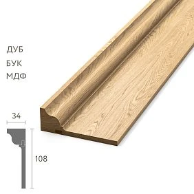
In the top view plan, the cornice may run along the wall, while the engineering element is located slightly farther from it. But the cornice has an overhang. If we take KZ-011 with a cross-section of about 108×34 mm and KZ-013 of about 90×90 mm, it becomes obvious that the same line along the wall creates a different depth of the detail.
The control section shows:
- wall;
- the ceiling plane;
- the actual cross-section of the selected cornice;
- the boundary of the engineering element;
- the design distances from the relevant section;
- the opening or servicing zone, if specified by the design.
There is no need to invent standard values. The cross-section is needed to visually and dimensionally compare the data that already exist in the design.
If the profile is shown on paper as a conventional 1 mm thick line, a large relief cornice seems to take up no space. The cross-section restores its real volume.
A full-size sample is useful where doubt remains on the drawing
A physical sample does not replace an engineering design. It helps verify the spatial perception of an already approved assembly.
A sample is especially useful if:
- deep cornice;
- a large grille or diffuser is located nearby;
- the unit is clearly visible to the visitor;
- there is doubt about how closely the two elements appear together;
- a series of identical rooms is planned.
You can place the actual profile against a mock-up of the wall and ceiling section, mark the actual boundary of the engineering element, and assess not only physical compatibility but also visual quality.
In a typical hotel room, one such sample is significantly cheaper than reworking dozens of identical sections after delivery.
Engineering can be the reason to compare two architecturally acceptable cornices
If the approved profile systematically conflicts with the engineering zone, the designer can consider several architecturally suitable options. But this decision is not made by the purchaser alone.
For example, in the STAVROS catalog:
- KZ-006 — compact profile approximately 55×20/22 mm;
- KZ-011 — approximately 108×34 mm;
- KZ-013 — approximately 90×90 mm.
These models demonstrate how different the actual offset can be. If the engineering allows one option and conflicts with another, this is useful information for the architect. But changing KZ-013 to KZ-006 just because "it's easier to pass by the grille" without architectural approval is not acceptable.
After approval of the specific article number cornice wholesale it is then calculated based on the actual product length of the selected version.
A typical hotel room must be verified as a unified architectural and engineering module
If the room is repeated 100 times, coordinating a single reference unit can cover a huge portion of the project. But only provided that the architecture and engineering truly repeat.
For the reference room, the following are overlaid:
- architectural wall elevation;
- ceiling plan;
- curtain track route;
- ventilation;
- electrical wiring;
- fire automation;
- service elements;
- tall furniture and other upper structures.
Then each conflict receives a status and a resolution. Only after that does the room become standard not only in design, but also in coordination.
Why visualization is not enough
Visualization often does not show technical equipment or shows it schematically. It answers the question of appearance, but does not confirm the physical compatibility of all engineering elements.
Why a mirrored room requires separate verification
The architectural layout may be mirrored, but the engineering points may not be. If ventilation or automation are located differently, the curtain track solution cannot be copied automatically.
For serial procurement via finishing material suppliers It is better to count standard and mirrored rooms separately until the identity of the nodes is confirmed.
A long corridor is better divided into coordination sections
Trying to check 40–60 meters of corridor in one line is inconvenient. Along it, doors, grilles, light fixtures, signs, sensors, turns, lowered ducts, and service areas may alternate.
It is useful to divide the corridor along natural boundaries:
- door groups;
- turns;
- engineering nodes;
- ducts;
- sections with a different ceiling level;
- formal and technical zones.
For example:
| Section | Length | Engineering | Risk | Solution |
|---|---|---|---|---|
| K-01 | 8200 мм | 2 grilles, 1 sensor | Low after the cut | Continuous line |
| K-02 | 3650 мм | Box | Medium | Separate transition |
| K-03 | 5400 мм | Service hatch | High | Requires approval |
After such a breakdown, it becomes clear where a long solid element is needed, and where engineering already creates a natural boundary that allows for a separate section.
for wholesale building material suppliers such a schedule is more useful than a single line “corridor — 80 m,” because each zone has its own readiness status.
Halls, the main entrance, and the reception require separate coordination
In formal areas, an accidental break in the wooden cornice is especially noticeable. At the same time, more engineering is often concentrated here: ventilation, complex lighting, sensors, loudspeakers, decorative ceilings, service elements.
For the hall, it is useful to check separately:
- the main entrance axis;
- the wall behind the reception;
- transition to corridors;
- long continuous walls;
- corners that are visible from a great distance;
- areas with several utility devices located next to each other.
If the equipment conflicts with the cornice, the decorative line should not be interrupted by random short breaks. The architect and engineer must determine where it is more reasonable to preserve continuity, where a planned boundary is acceptable, and which junctions require separate treatment.
This approach is especially important when ordering building materials wholesale from the manufacturer for feature areas: the bulk batch must correspond to the already approved spatial scheme.
After coordination, the cornice route must be recalculated
Before the engineering review, the project may have a provisional perimeter of 32 m. After approval, it turns out that:
- in one section, the cornice remains continuous;
- a planned gap appears at the service hatch;
- two short sections are added in the duct area;
- one wall receives a different termination;
- part of the profile transitions to another plane.
The final schedule must reflect this approved route.
| Room | Section | Article | Finished length | Start | End | Engineering unit |
|---|---|---|---|---|---|---|
| Hall | X-01 | KZ-011 | 5200 мм | Angle | Gap | Hatch nearby |
| Hall | X-02 | KZ-011 | 1100 мм | Gap | External corner | Engineering box |
| Corridor | K-07 | KZ-011 | 2400 мм | Angle | Angle | No conflict |
This structure allows cutting to be planned only after all gaps and terminations have a clear reason and approved status.
An engineered split can improve the cutting layout or, conversely, make it more complex
Not every split increases consumption. If a long wall of 5200 mm is divided by an engineered joint into 2400 + 2600 mm, this may align well with the commercial lengths of the selected version.
But if the same wall is split into 1750 + 450 + 3000 mm, more short parts and offcuts appear.
Therefore, the net sum of lengths does not show the purchase volume.
When a split helps
- aligns with a logical architectural termination;
- provides convenient lengths;
- allows avoiding a random joint in the middle of a feature wall;
- a short offcut can be used in another area.
When a split worsens the situation
- creates several very short pieces;
- requires two new open ends;
- appears in the most prominent part of the wall;
- breaks the rhythm of the relief cornice;
- does not allow rational use of the original plank.
After coordination wholesale purchase of building materials can already rely on real segments rather than the preliminary architectural perimeter.
First, long continuous sections are allocated
Long feature walls have fewer cutting options. Therefore, in the final map, the original planks are reserved for them first.
Sequence:
- identify the longest segments;
- check where joints are permissible;
- assign base planks of the selected commercial length for them;
- record the remnants;
- use suitable remnants for short engineering-determined sections;
- only then calculate the purchase quantity.
If KZ-011 made of solid wood with a length of 2400 mm is selected, a 4600 mm segment will require at least two base planks and a pre-agreed joint. A short 700 mm segment next to the duct can potentially be covered with a remnant from another wall. For MDF of the same article, the commercial length is 2600 mm — the cutting layout is already different.
Therefore, an article without the material and commercial length is insufficient for a procurement list.
A change in the engineering design requires a local recalculation, not an automatic rework of the entire project
After architectural approval, engineers may move the grille, sensor, or another element. This does not mean that the entire cornice needs to be recalculated from scratch.
First, the zone of influence is determined:
- which rooms are affected;
- which wall;
- which cornice segment;
- whether the change falls into a corner;
- whether it falls at a joint;
- whether a new end appears;
- whether the finished length changes.
If the grille was moved within the free zone and the conflict is resolved, the linear footage may remain the same. If the new position falls at an end or corner, local reworking of several parts will be required.
This approach makes it possible not to disrupt an already verified specification because of a single engineering change.
One moved grille can change several parts at once
Let's imagine that the grille was initially located in the center of the long wall and did not conflict with the cornice. After the revision, it was moved closer to the corner.
The new position may affect:
- the last 500–700 mm of one wall;
- the inner corner itself;
- the first element of the adjacent wall;
- the location of the previously planned joint.
In other words, a local engineering shift can change three rows of the cutting map at once. Therefore, the adjustment is checked against the combination of adjacent segments, not by a single number.
Who is involved in coordination and where the purchaser's responsibility ends
The list of participants depends on the project, but usually the following are involved in the approval:
- architect or designer;
- engineer of the relevant discipline;
- kit assembler or purchaser;
- installation organization;
- technical client or coordination service — if provided for by the project.
The purchaser is responsible for not sending an uncoordinated scope into production. They can:
- show the cornice dimensions;
- record the intersection;
- compile a map of problem areas;
- request a solution;
- update the procurement list after approval.
But he should not design the new layout of the engineering equipment himself.
If the project works through building materials supplier, the supplier also receives the already approved version, not a set of disputed options.
Practical scenario: a ventilation grille conflicts with a curtain rod in 40 identical rooms
In the hotel, one wooden curtain rod was chosen for the standard room. The architectural plan is approved, the footage is calculated. When the ventilation is overlaid, it turns out that on one wall the grille comes so close to the upper corner that the deep profile partially falls into the same spatial zone.
Incorrect scenario
Purchase the entire curtain rod, and then ask the installers to "carefully trim near the grille."
Consequences:
- 40 identical random gaps;
- different end lengths for different crews;
- unpredictable appearance of the end faces;
- changed actual consumption;
- impossibility of using the original standard cutting map.
Correct scenario
- apply the actual dimensions of the cornice and grille to a single assembly;
- show the conflict to the architect and ventilation engineer;
- obtain an approved decision;
- assemble one control fragment;
- record the lengths of all affected parts;
- apply the approved scheme to genuinely identical numbers;
- only then process the main batch.
If the project is being implemented in Moscow in several phases, building materials Moscow wholesale it is more convenient to produce using already proven standard units, and to keep non-standard rooms in a separate schedule.
Practical scenario: a long curtain track runs next to a service hatch in the lobby
The lobby features an expressive KZ-013. According to the architecture, one line should run almost without interruptions along the main wall. A service hatch is located nearby on the ceiling.
In the top view there is no intersection: the hatch is located higher and slightly further from the wall. But in the section, the deep profile of about 90 mm approaches the opening trajectory.
Before producing the long parts, it is necessary to check:
- the actual angle or direction of opening;
- whether the panel needs to be removed completely;
- how much space is provided for access;
- whether the curtain track can remain continuous;
- if a break is needed — where it is architecturally best to place it.
If the split is ultimately approved, it changes more than just the appearance. Instead of one long wall, two separate segments appear. Sometimes this improves the cutting layout, sometimes it does the opposite and creates two awkward remnants.
Therefore finishing materials wholesale moscow for formal areas, it makes sense to assemble after the service units are approved, not just after the profile is selected.
Practical scenario: after architectural approval, new sensors were added
The cornice has already been approved, and the first version of the cutting layout is ready. Then the engineering section receives a revision: new sensors are added in some of the rooms.
There is no need to automatically invalidate the entire calculation.
First, a list of changes is compiled:
| Room | New element | Cornice section | Does the length change? | Is a new node needed? |
|---|---|---|---|---|
| Number 214 | Sensor | K-03 | No | Check |
| Number 216 | Sensor | K-03 | Yes, if a break is needed | Yes |
| Hall | Sensor | X-08 | No | No conflict |
After coordination, some lines may remain unchanged. Only the actually affected sections are recalculated.
This keeps the specification manageable: an engineering revision does not turn every change into a full recalculation of the project.
Practical scenario: an engineering box splits one wall into three segments
Initially, a single decorative cornice 6200 mm long was supposed to run along the wall. After installing the box, the following route was approved:
- 2300 mm;
- short transition 650 mm;
- 2700 mm;
- two external corners;
- two internal transitions.
The net sum of the sections became even smaller than the original line. But the number of parts increased, and two segments exceed the commercial length of the 2400 mm array for some current KZ profiles.
This means the purchased volume may not decrease proportionally to the net linear meters. Additional source elements and new joint locations will be needed.
This is a clear example of why wholesale cornices from the manufacturer cannot be calculated only by the final length after all deductions. A map of individual segments is needed.
When engineering does not require changing the cornice
There is no need to turn coordination into a search for a problem where there is none.
The cornice can be left unchanged if the current documentation confirms that:
- engineering elements do not intersect its actual volume;
- access and maintenance are not blocked;
- there are no requirements to change the architectural route;
- all standard rooms indeed repeat a proven assembly;
- the next revision of the project does not affect the upper zone.
In this case, the coordination check ends with a "no conflict" status, and procurement proceeds according to the original architectural schedule.
The expert process should not complicate a simple assembly, but rather distinguish it in time from a genuinely conflicting one.
The final schedule should separate architectural gaps from those caused by engineering systems
Two equally short sections may have different causes:
- one ends at a curtain niche;
- another — at an engineering box;
- a third — at an approved service access;
- a fourth — an ordinary cutting joint.
The reason must be stored in the table. Otherwise, during the next revision, the team will not understand whether the gap can be removed or whether it is related to an engineering system.
| Section | Length | Reason for termination | Can it be changed without re-coordination? |
|---|---|---|---|
| K-12 | 1450 мм | Curtain niche | No, if the niche changes |
| K-13 | 900 мм | Service hatch | No |
| K-14 | 2200 мм | Cutting joint | Yes, within the approved line |
When delivery of finishing materials such a schedule helps avoid confusing a structurally necessary gap with an ordinary installation joint.
The specification must have a version corresponding to the engineering revision
If architecture works from one revision, engineering from another, and procurement from a third, even the right decisions lose their meaning.
For a cornice batch, it is useful to record:
- the architectural revision number;
- the dates of the engineering plans used during coordination;
- the version of the cornice schedule;
- approval status;
- the list of open questions — if any remain.
Only a version without unresolved conflicts in the zones included in the current batch should go into production.
This is consistent with the general logic materials in bulk: the identity of the item and the current version of the project data matter more than a random file name like “final.”
Phased procurement helps avoid delaying completed zones because of a few complex assemblies
On a large project, some rooms may be fully coordinated while the lobby and restaurant are still changing. You don't have to choose between two extremes: waiting for the entire project or ordering everything based on a disputed version.
It can be divided:
- batch 1 — standard rooms with no open conflicts;
- batch 2 — corridors after final engineering coordination;
- batch 3 — lobbies and non-standard public areas;
- batch 4 — repair reserve after actual installation.
With this approach, construction materials are purchased wholesale in Moscow based on the actual readiness of zones, rather than on a single artificial date when "the entire project is approved."
The coordination register must store the decision, not just a conflict flag
A conflict map is useful at the first stage, but before purchasing it needs to be turned into a register of closed nodes. A single "yes / no" column is not enough: a few weeks later, no one will remember why a specific section became shorter or why a gap appeared in a standard room.
For each potential conflict, it is useful to record:
| Field | What to record |
|---|---|
| Assembly code | Unique identifier |
| Room | Number / zone |
| Cornice section | Code from the schedule |
| Engineering system | Ventilation / automation / service access / other |
| Issue | What exactly intersects or requires verification |
| Responsible person | Who issues the technical solution |
| Solution | No conflict / gap / new route / different assembly |
| revision | Plan version on which the solution applies |
| Impact on procurement | No / length changed / new segment appeared / SKU changed |
Such a register is especially valuable if the project lasts several months. It links engineering coordination with the procurement list and allows you to verify that every changed part has a clear reason.
If the engineering revision changes later, the team does not review the entire project. It selects only the nodes tied to the affected system or revision.
Calculation example: 40 rooms show how one engineering gap changes the purchase quantity
Suppose that in a typical room, a continuous cornice section of 4700 mm was planned along one wall. A solid profile with a commercial length of 2400 mm was selected. Before engineering coordination, this wall required two original strips:
2400 + 2400 = 4800 mm.
The remainder after fitting is about 100 mm before accounting for finish cuts.
After coordinating the ventilation grille, the planned gap is approved. The wall turns into two sections
After this point, any new change is treated as a new revision with a check of the impact on already ordered material.
This does not automatically mean stopping production. First, it is checked whether the already ordered lengths can be used in the new route. Sometimes an engineering change only alters the joint location or moves a short remainder to another section without changing the quantity.
If the new revision affects long continuous segments, a decision must be made before they are cut or shipped.
The impact of engineering on the SKU selection must be separated from its impact on quantity
A conflict has two fundamentally different outcomes.
The SKU remains the same
Only the route changes:
- a gap appeared;
- the end point shifted;
- a short section was added;
- the joints were distributed differently.
Then the quantity and cutting layout are recalculated, but the product item remains the same.
The architect approves a different profile
If the engineering density of the zone makes the original cornice unsuitable, the architect may approve a different cross-section. Then you need to re-check:
- dimensions;
- the material;
- finish;
- commercial length;
- joints;
- corners;
- the entire cutting map.
You cannot transfer the quantity of the original SKU to the new one just because the net wall footage has not changed.
This is especially important when building materials wholesale from the manufacturer are produced to order: a change of cross-section is a full revision of the product specification.
A critical engineering node must be checked before cutting the longest planks
The most expensive situation is when long elements have already been cut for the original route, and then the engineering node changes the wall length or the end point.
To avoid this, the sections can be divided:
- GREEN — coordination is closed, cutting can begin;
- YELLOW — the profile is selected, but the node is still being checked;
- RED — there is a confirmed conflict, cutting is prohibited until it is resolved.
Such a status does not necessarily need to be shown in the final article as a color system on the site; the principle matters: a disputed area must not accidentally end up in the production cutting along with the finished ones.
It is better to first reserve long strips for areas with the status “done.” After the remaining nodes are closed, the map is updated.
Checking after installing the first phase improves the next coordination
Even a well-developed project is useful to verify against the real site after the first phase.
Compare:
- whether the dimensions of the engineering elements matched those used in coordination;
- whether there were enough sections and elevations;
- whether any unexpected service routes appeared;
- where installers had to clarify nodes additionally;
- whether the actual consumption matched the cutting map;
- which short segments produced more waste.
If the first phase reveals a systemic problem, the cause is corrected before the next batch. You cannot simply increase the cornice reserve: extra material does not resolve a spatial conflict.
For a phased project, the delivery of finishing materials becomes more accurate when actual data from the first phase is fed back into the next procurement version.
Before production, it is useful to compare the design coordination with the actual upper zone
Even approved drawings are worth verifying against the site where engineering elements have already been installed or their position can be accurately confirmed. The purpose of the check is not to redesign the engineering systems, but to ensure that the procurement list is based on up-to-date geometry.
This is especially important for:
- grilles and diffusers near corners;
- hatches that open toward the cornice;
- ducts whose actual dimensions differ from the early schematic;
- ceiling devices in mirrored rooms;
- public areas with several engineering systems at once.
If the actual position matches the approved plan, no changes are required. If it differs, the section receives a new status and is returned for coordination.
What to record during such a check
A few facts are enough:
- room code;
- cornice section code;
- which engineering element was checked;
- whether its position matches the working documentation;
- whether the difference affects the route, length, or end of the cornice.
There is no need to turn this check into a full geodetic report unless the project requires it. It is needed as a final safeguard against mass production based on outdated geometry.
The production package should contain only finalized decisions
By the time of the final order to the supplier, it is better to hand over a compact but unambiguous set:
- exact article number and finish;
- current schedule of sections;
- number of source strips according to the cutting plan;
- separation by rooms or phases;
- version of the specification;
- a separate list of non-standard sections if they are supplied separately.
There is no need to send the supplier the entire array of internal engineering discussions. Their task is to manufacture and supply the already approved profile in the required quantity.
If some rooms remain disputed, it is better to exclude them from the current batch than to leave a note saying "we'll sort it out during installation."
For the supply of finishing materials, this is especially important: the supplier must see one active procurement version, not several parallel options.
After coordination, it is necessary to check whether the commercial logic of the order has been lost
Engineering work can significantly change the architectural schedule: new short segments, breaks, separate zones, and new terminations appear. After that, it is useful to perform a final commercial check.
It answers the questions:
- whether an extra item code has appeared without a real need;
- whether solid wood and MDF are mixed in one line;
- whether the product length matches the selected material;
- whether the same section has been ordered twice;
- whether there is a reasonable reserve;
- whether offcuts of long planks can be used for short engineered segments;
- whether rooms with unresolved conflicts have been included in the batch.
This is the last stage before ordering: engineering coordination is already complete, and the purchaser checks that its result has been correctly converted into a commercial quantity.
20 typical mistakes when coordinating a curtain track with ceiling engineering
1. Calculating the curtain track based only on the architectural plan
Why it happens: the architectural schedule is the one that contains the item code and preliminary linear footage. Consequence: after delivery, engineering clashes are discovered. How to prevent it: before ordering, overlay the current engineering plans onto the cornice route.
2. Check only the ventilation
Reason: the grilles are the largest and most noticeable. Consequence: sensors, access panels, fire-safety elements, loudspeakers and other devices go unnoticed. Prevention: use the complete list of engineering elements for the specific project.
3. Look only at the front view
Reason: on the elevation, the decorative line looks unobstructed. Consequence: the deep profile clashes with equipment in three dimensions. Prevention: create sections of critical junctions.
4. Ignore the cornice projection
Reason: the cornice is perceived as a decorative strip. Consequence: KZ-013 and the compact KZ-006 are mistakenly considered spatially identical. Prevention: draw the actual cross-section of the selected item code.
5. Rely on the axis of the engineering element instead of the outer dimension
Reason: that is how the element is shown on a schematic plan. Consequence: the actual grille or diffuser ends up closer. Prevention: verify the actual visible boundary of the equipment.
6. Relocate the sensor or grille yourself
Cause: the shift seems minor. Consequence: the purchaser effectively interferes with the engineering design. Prevention: only record the conflict and obtain a decision from the responsible designer.
7. Reduce the cornice independently
Cause: the smaller profile physically fits. Consequence: the approved architectural concept is violated. Prevention: any change to the item code must go through the architect.
8. Cut the cornice around equipment "on site"
Cause: it is a quick way to finish installation. Consequence: random gaps and mismatched ends appear. Prevention: an approved standard detail before series production.
9. Not checking the hatch opening trajectory
Cause: the outlines on the plan do not intersect. Consequence: after installation, access is blocked by the volumetric profile. Prevention: check the section and the maintenance scenario.
10. Not checking the standard number before printing
Cause: the architecture seems repeatable. Consequence: one error is scaled across dozens of rooms. Prevention: a reference coordination number.
11. Automatically transferring the solution to mirrored unit numbers
Cause: the layout is mirrored. Consequence: engineering points may be positioned differently. Prevention: verify the engineering layout separately.
12. Do not split a long corridor into sections
Cause: it is easier to count as a single length. Consequence: local engineering zones and the reasons for breaks are lost. Prevention: coordination segments.
13. Do not record the reason for the cornice ending
Cause: only the length matters in the schedule. Consequence: during review it is unclear whether the break can be removed. Prevention: an “engineering node / reason for ending” field.
14. Recalculating the entire project because of one shifted element
Cause: any change seems global. Consequence: extra work and new errors in unaffected zones. Prevention: first determine the area of impact.
15. Not checking adjacent segments when moving the grille
Cause: they look only at the wall with the equipment. Consequence: the change lands in a corner or at the joint of an adjacent part. Prevention: check the set of segments around the node.
16. Building the cutting plan before closing engineering statuses
Cause: you want to get the quantity in advance. Consequence: the map quickly becomes outdated after gaps are approved. Prevention: coordinate first, then cut.
17. Treat net square footage as equal to purchased
Cause: all areas are already known. Consequence: short engineering segments and commercial lengths create additional waste. Prevention: convert parts into whole source planks.
18. Send a disputed version to the supplier
Cause: procurement deadlines are tight. Consequence: the manufactured batch matches an already outdated geometry. Prevention: only the approved revision goes into the order.
19. Check only typical rooms and forget the lobbies
Cause: the main volume is in the rooms. Consequence: the most scenic and engineering-heavy areas are left for later. Prevention: separate coordination for formal spaces.
20. Try to solve an engineering problem with a discount or extra material stock
Cause: extra planks seem to provide flexibility. Consequence: the physical conflict remains, and extra material is purchased. Prevention: an approved detail first, then the quantity.
When a wholesale order is better stopped, even if the SKU and price have already been agreed
Wholesale cornices from the manufacturer should not be launched into mass production if open questions remain for at least a substantial part of the premises:
- there is no current engineering ceiling plan;
- actual cornice dimensions have not been marked;
- ventilation elements have not been checked;
- sensors and fire safety devices have not been coordinated;
- service hatches have not been checked;
- engineering ducts are still being changed;
- gaps and terminations have not been closed;
- the standard number has not passed coordination;
- the schedule still contains “check” statuses without an assigned decision-maker.
At the same time, there is no need to block the entire project because of one hall. A phased approach allows ready-made standard zones to be released separately.
If the project operates through wholesale building materials directly from the manufacturer, it is useful to specify directly in the order which revision of the premises is considered approved.
Checklist before ordering a wooden cornice
| Check | Done |
|---|---|
| The exact cornice article number has been approved | ___ |
| Its actual height, depth, and projection have been verified | ___ |
| There is a current architectural ceiling plan | ___ |
| There are current engineering plans | ___ |
| Ventilation grilles and diffusers are marked | ___ |
| Sensors are marked | ___ |
| Fire protection system elements are marked | ___ |
| Service hatches marked | ___ |
| Engineering boxes marked | ___ |
| Other ceiling devices of the project checked | ___ |
| Map of potential conflicts compiled | ___ |
| Critical nodes checked in section | ___ |
| Standard rooms coordinated | ___ |
| Mirrored rooms checked separately | ___ |
| Corridors divided into sections | ___ |
| Lobbies and entrance areas checked separately | ___ |
| All gaps have an approved reason | ___ |
| All endings are coordinated | ___ |
| The final list of sections has been issued | ___ |
| Only after this is the cutting map built | ___ |
If finishing materials are purchased wholesale in Moscow for several buildings, it is convenient to go through this list separately for each phase.
Decision tree: what to do when an engineering element is found next to the cornice
Is there an actual intersection on the plan or section?
No. We record "no conflict" and keep the route.
Yes or unclear. We move on to the section and check the actual dimensions.
Does the conflict concern an engineering system?
Yes. We refer the matter to the responsible engineer. The purchaser does not propose a relocation on their own.
No, it's purely a matter of decorative geometry. We're passing it to the architect to determine the route or profile.
Has the cornice break been approved?
Yes. We lock in the exact start and end points, add them to the schedule, and recalculate the cutting layout.
No. We are not releasing the disputed section to production.
Is the assembly repeated in standard rooms?
Yes. We check one reference unit, then confirm that the engineering is indeed repeated.
No. We handle it as a separate non-standard assembly.
Did the change affect only one wall?
Yes. We recalculate it and the adjacent linked segments.
No. We determine a broader area of impact before updating the specification.
Final algorithm for coordinating the curtain track with ceiling engineering
SELECT THE SKU → CONFIRM ITS FULL DIMENSIONS → OBTAIN THE ARCHITECTURAL CEILING PLAN → OBTAIN THE CURRENT ENGINEERING PLANS → PLOT THE CURTAIN TRACK ROUTE → PLOT VENTILATION → SENSORS → FIRE-PROTECTION ELEMENTS → HATCHES → DUCTS → OTHER EQUIPMENT → CREATE A CONFLICT MAP → MAKE SECTIONS OF CRITICAL POINTS → PASS QUESTIONS TO THE RESPONSIBLE DESIGNERS → OBTAIN APPROVED DETAILS → CHECK REFERENCE ROOMS → CHECK NON-STANDARD ZONES → RECORD BREAKS AND ENDINGS → RECALCULATE THE ROUTE → BUILD THE CUTTING PLAN → FORM THE WHOLESALE ORDER.
- Do not start with the bare square footage.
- Check the full extent of the curtain track.
- Combine architecture and engineering.
- Do not limit yourself to ventilation.
- Check service access separately.
- Do not assign regulatory distances on your own.
- Do not relocate engineering equipment without authorization.
- Do not change the SKU without the architect.
- Record every potential conflict.
- Make a cut where the top plan is insufficient.
- Use a physical sample if necessary.
- Close the standard number first.
- Check the mirrored variant separately.
- Divide a long corridor into sections.
- Check halls as separate entrance zones.
- Record the reason for each gap.
- After an engineering revision, recalculate only the affected area.
- Distribute long continuous parts first.
- Close short segments with suitable offcuts.
- Send only the approved version to the supplier.
Bottom line: the cornice must be coordinated with the actual engineered ceiling before purchase
A beautiful architectural cornice in a rendering is not yet a product ready to order. For a commercial project, it is necessary to confirm that its actual volume is compatible with all equipment in the upper zone, and that service and engineering requirements do not create accidental gaps after delivery.
The correct sequence is:
ARCHITECTURE → ENGINEERING → SPATIAL COORDINATION → APPROVED ASSEMBLIES → FINAL ROUTE → SEGMENTS → CUTTING PLAN → NUMBER OF SOURCE STRIPS → ORDER.
This way, wholesale cornices from the manufacturer do not have to be redone after the equipment has already occupied the ceiling.
If materials are purchased wholesale at the same time, the cornice must still remain a separate product line with its own route, engineering assemblies, and specification version.
Final check before sending the order to the supplier
After engineering coordination is closed and the cutting map is built, it is useful to perform one final check for each room type. It should not reopen the design process. Its task is to verify that the approved solutions are correctly translated into purchasing lines.
For a standard room, verify: SKU, material, commercial length, number of straight segments, number of open ends, presence of engineering-related gaps, and the number of source strips according to the cutting map. For the hall, additionally check long feature sections and the reserve for them. For the corridor, check the sequence of coordination segments and whether the gaps match the current engineering revision.
It is especially useful to compare three figures:
- the clean route — how many metres of cornice actually remain after all approved breaks;
- the purchase volume — how many metres are contained in whole original items that need to be ordered;
- the useful reserve — which whole strips or long offcuts should remain after installation.
If the purchase volume differs unexpectedly strongly from the clean route, this is not a reason to automatically reduce the order. First, you need to check whether engineering breaks are creating inconvenient lengths, whether whole strips are reserved for feature walls, and whether different materials with different commercial lengths are mixed in one line.
Only after this reconciliation is the order considered truly ready: the engineering part is no longer in dispute, the architectural profile is confirmed, and the commercial quantity is explained by specific segments and cutting.
For a repeat phase of the project, the same package can be used as a base, but before copying you need to check whether the engineering layout has changed. Matching architecture does not yet guarantee matching ventilation, automation, and service zones. If the engineering points differ, the standard cornice route is retained only after a new local check. This allows the already established methodology to be reused without mechanically transferring the old solution to rooms with different technical equipment.
Frequently asked questions
Should a ventilation grille be moved if it is close to the cornice?
Not automatically. The potential conflict needs to be recorded and passed to the responsible designers. The article does not determine the position of engineering equipment.
Can you simply choose a smaller cornice?
Only after architectural approval. A smaller cross-section may resolve the physical conflict, but it would change the design of the room.
Why make a section view if everything fits on the top-down plan?
Because both the cornice and the equipment have depth and projection. The conflict can only arise in three dimensions.
Should a single minimum distance from all sensors to the cornice be specified?
No. Universal distances are not established by this article. Requirements depend on the specific system, equipment, and design documentation.
Can the cornice be cut around a sprinkler or sensor?
Only if the relevant architectural and engineering detail is approved by the responsible specialists. An installer's unilateral decision is unacceptable.
Why should the service hatch be checked separately?
Because its outline may not intersect with the cornice, but its three-dimensional profile can fall within the opening or servicing trajectory.
How should 100 identical hotel rooms be checked?
First fully coordinate the reference number, then confirm that the others truly replicate it both in architecture and in engineering. Mirror variants are checked separately.
When should the final linear footage be calculated?
After approval of all breaks, terminations, duct enclosures, and other engineering-driven route changes.
Do I need to recalculate the entire project after moving a single grille?
No. First the zone of influence is determined, and only the affected segments are recalculated together with adjacent corners and joints.
What should be sent to the supplier?
The approved article and finish, the final schedule of sections, the quantity of source products by cutting plan, the delivery stage, and the current version of the specification. The supplier must not guess at unresolved engineering decisions.