Article Contents:
- Separate decor by installation task
- The overall dimensions of the part and the installation size do not always match
- Overlay decor is selected for the actual free field
- The back surface determines whether installation is possible
- Check access for fastening
- How to mark out a row of rosettes
- When point decor is more suitable than elongated
- Decorative and supporting functions must be distinguished
- Plan for access after assembly
- The outer and inner dimensions of the frame differ
- The number of product strips is determined by the cutting map
- Finishing and gluing cannot be assigned separately from each other
- Can a flat applique be installed on a curved surface
- Is interior wooden decor suitable for outdoor use
- Can I order only the missing element after assembly
The applique fits on the facade, but its back side falls on the step between the frame and the panel. The bracket looks good from the front, but from the side it protrudes beyond the shelf. The molding is sufficient in overall length, but the required continuous segment can no longer be obtained from the remaining pieces. In all three cases, the mistake begins with one habit: evaluating a decorative detail only by its front appearance.
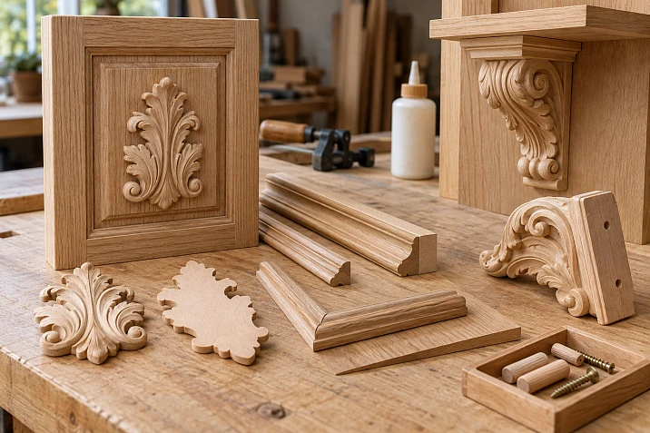
It is more convenient to choose decorative woodcarving elements starting from the installation location. First, the adjoining surface and the free space are determined, then the shape of the detail, its dimensions, and the operations that will be required in the workshop. For an applique, the back surface may be decisive; for a rosette, the position of the center; for a capital, the junction with the pilaster; for a molding, the cross-section and the cutting map.
Ready-made carving removes the work of forming the ornament. But fitting, marking, joining to the base, and coordinating the finish remain part of your project. Before purchasing, you need to understand exactly how the chosen detail will fit into it.
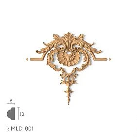
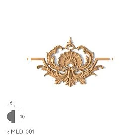
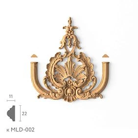
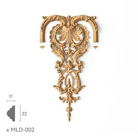
Separate decor by installation task
The single name “decorative wooden elements” unites products with different application technologies. A small rosette is marked relative to the center. A long profile is divided into segments and assembled into a frame. A capital is selected for a vertical detail and the top termination. They cannot be checked against one universal list of width and height.
For work, it is convenient to use five groups. This is a practical division by the main task, not a strict classification of all possible shapes. A rosette can also be mounted as an overlay, a capital can be three-dimensional, and corner decor participates in assembling a linear surround. In the specification, the detail is assigned to the group that determines its main installation check.
| Group | Examples | What is checked first | Main work in the workshop |
|---|---|---|---|
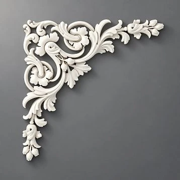
| Applied decor on a flat surface | Carved overlay, corner element | Free field, thickness, reverse surface | Fitting, marking, preparing the fastening |
| Point decor | Wooden rosette | Overall dimensions, center, pattern orientation | Alignment to an axis or repeating module |
| Volumetric decor | Bracket, protruding cantilever part | All three dimensions and adjoining surfaces | Checking the assembly in multiple views |
| Composite architectural decor | Capital, pilaster, base | Joints and final assembly size | Alignment of multiple parts |
| Linear decor | Molding, carved trim | Cross-section, length, joints and ends | Cutting, sawing, joining |
This division immediately changes the selection order. If a long panel edge needs to be decorated, the profile is considered first. If the center of a small field needs to be highlighted, compact rosettes and overlays are compared. If a part connects the vertical and horizontal parts of the composition, start with the cut of this node.
The style is chosen within a suitable group. A floral ornament by itself does not suggest the installation method: it can be on a flat overlay, a deep capital, or a long baguette. Buying by a single design leaves the main question unanswered — where and how the product will contact the base.
Catalog carpentry decorative elements it is useful to browse with a specific installation task in mind. Then the choice narrows down to the parts that physically fit the project.




The overall dimensions of a part and the installation dimension do not always coincide
Product cards may contain letter designations for dimensions: A, B, C, L, and others. Their meaning is determined from the drawing of the specific product. The direction of a dimension cannot be carried over from one product group to another just because the letter is the same.
For individual decorative pieces, three spatial dimensions are usually checked. For profiles, the cross-section and the length of the commercial strip are read separately. But the outer dimension does not always show what is needed for connection. The widest part of a capital may be at the top, while a narrower lower section mates with the pilaster. For an overlay, the maximum thickness is at the relief, while contact with the base occurs along a different surface.
In a working drawing, it is useful to distinguish:
- outer dimension — how much space the element occupies as a whole;
- mating dimension — which part connects to the adjacent component;
- installation position — where the element is located relative to the chosen plane and axis;
- clearance — what remains for movement, access to the fastening, and finishing.
For example, the protrusion of an overlay after installation is measured from the actual surface of the front. If a shim is provided underneath it, the final protrusion will change. If part of the product fits into a prepared recess, the outer thickness is no longer equal to the visible protrusion. Such solutions cannot be guessed from a photograph: they must be shown in a section view.
For repeatable layout, choose one reference edge and one primary plane. It is better to set out the dimensions of adjacent elements from a common base rather than sequentially from each other. Otherwise, a slight offset of the first decorative element will carry over to the second and become noticeable by the end of the row.
In the section drawings and product models you can also search for technical materials for selection. Before use, check that the file corresponds to the selected article number and size version. A similar appearance does not yet mean that the mounting dimensions match.
Our factory also produces:
Overlay decor is selected for the actual free field
A furniture front has an overall size and an area on which the decoration can be placed. These values rarely coincide. Part of the surface is occupied by the frame, moldings, handle, and edge of the panel. On a door, additionally check the space near the adjacent cabinet and the opening path.
Before selection wooden decorative overlays outline exactly the available field. If it is curvilinear, one width is not enough: a long ornament sheet may extend beyond the boundary where the overall rectangular dimension still looks suitable. For such parts, a full-size contour is useful.
Let us consider a conventional front 420 mm wide and 620 mm high. From the outer edge to the outer boundary of the molding frame, 30 mm is left on each side, and the width of the profile itself in the front plane is 20 mm. Then the free field inside the frame is:
Width: 420 − 2 × 30 − 2 × 20 = 320 mm.
Height: 620 − 2 × 30 − 2 × 20 = 520 mm.
A conventional overlay with an overall size of 240 × 400 mm, after centering, will leave 40 mm on each side and 60 mm at the top and bottom. These numbers show the geometric placement. They do not set mandatory proportions for the decor and do not take into account the handle if it must be located in the same field.
With a horizontal handle on top, it is not necessary to keep the top and bottom margins equal. First, comfortable finger access is provided and hand movement is checked, then the composition is built. Mechanically centering the entire overlay on the front sometimes places the most protruding section directly under the grip.
Thickness is assessed separately from area. Two decorative furniture overlays identical in width and height can behave completely differently near an adjacent door. For one, checking the flat contour is enough; for the other, a mock-up of the protrusion and a trial opening will be required.
You should not automatically reduce an overlay by trimming. On a symmetrical ornament, cutting the edge changes the pattern, and on a thin branch it may remove part of the area needed for fastening. If the part does not fit, first compare another size or another shape. Fitting is provided only where it is permissible for the specific product.
Get Consultation
The back surface determines whether installation is possible
The front relief is responsible for the visible composition. The back surface determines what the part rests on and where it can be fastened. It may be flat, have a recess for a profile, or another specified geometry. The outer contour says nothing about the actual contact area.
Place the element on the prepared base without glue and look at the joint from the side. If the part rocks, do not try to eliminate this immediately with strong pressure. First determine the cause: unevenness of the base, a protrusion on the back side, mismatched profiles, or deformation. A thin overlay pressed with force may remain held in a stressed state, and after the fixation is removed, it may tend to return to its original shape.
Joints between different surfaces require special attention. An overlay can visually cover the transition between the frame and the panel, but this does not mean it can be rigidly connected to both parts at once. If the panel construction allows movement, the decorative part must not block it. The fastening method is chosen taking into account the design of the front itself.
A similar problem arises on panels separated by a technological gap. Decor attached on both sides of a movable joint changes how the connection works. If the line needs to be hidden, a solution is devised that preserves the necessary freedom, or the element is relocated. There is no universal rule here of “cover with an overlay and glue over the entire area.”
Check access for fastening
Even with good contact, you need to understand how to hold the part during installation. The clamp must not rest on a fragile threaded edge. For pressing, a suitable pad may be needed that distributes the force over permissible areas and does not leave marks. Its shape is checked during a trial assembly.
If mechanical fastening is specified, first determine the access from the back side of the base, the material thickness, and the position of the fastener relative to thin areas of the ornament. The presence of three-dimensional relief does not give the right to drill it at an arbitrary location. The length and type of fastener are specified for the specific joint.
On an already painted base, assess the condition of the coating and the compatibility of the selected adhesive with both surfaces separately. The strength of the fastening depends not only on the adhesive composition: a weak old coating may detach along with it. Preparation is carried out according to the technology of the materials used and, if the result is unknown, after a trial test.
For applied decor, it is useful even before purchasing to answer three quite specific questions: which surface it adjoins, where it will be held, and how it can be fixed during installation. If at least one answer is missing, the shape has not yet been coordinated with the product.
The symmetry of the pattern and the installation side are checked separately
A symmetrical overlay usually allows centering along the axis of the pattern. For a directional ornament, the beginning, the end, and the side of opening are important. Two identical parts can produce a repeat, but not a mirrored pair.
Do not expect to get a right overlay from a left one by simply rotating it. A 180-degree turn moves the top to the bottom along with the pattern. Flipping it face down to the base hides the relief. Mirroring on a drawing is possible, but for a physical part it may require a different version.
If the manufacturer uses the designations L and R, keep them in the item code. For the installation list, add a Russian explanation: “left when viewed from the front side” or another reference adopted in the project. Separately check whether it matches the supplier’s designation. A single letter without a picture and an agreement on the viewing direction allows for error.
In a conventional composition on two doors, two left and two right overlays may be needed. An order for “four pieces” does not convey this information. It is split into two items with their own codes and quantities. After receipt, the entire set is laid out as it will stand on the furniture.
The direction of the pattern can be significant even for compact spot decor. A round or nearly round overall size does not guarantee that the part looks the same after any rotation. Therefore, rosettes also have their top marked when this is necessary for the composition.
The corner element is checked immediately in its corner of the frame. The part may fit a specific profile or have a rebate on the back side. A similar ornament from another group will not necessarily replace it in this joint.
The wooden rosette is aligned to the center and the surrounding field
The rosette creates a compact accent. It is convenient to consider it for the center of a small field, the completion of a repeating module, or a specially designed junction of decorative lines. A long overlay sets the direction more strongly; a rosette primarily marks a place.
When choosing wooden rosettes check the overall dimension in plane, the depth, the shape of the base, and the position of the pattern relative to the axis. Not all products in this group are round. For square, oval, or complex shapes, take measurements along the required directions rather than replacing them with a conventional diameter.
For example, in the product page wooden rosette R-084 versions are given as 45 × 45 × 13, 55 × 55 × 16, 74 × 74 × 19, and 95 × 95 × 24 mm. As the overall size increases, the third dimension also changes. Therefore, choosing a large option based only on the front view is not enough: its projection must also be included in the check.
How to lay out a row of rosettes
First determine what should repeat: the distance between centers or the free gap between contours. These are different layout methods. For a row of identical products they are simply related, but when sizes alternate they produce different results.
A conventional example: three round rosettes with a diameter of 60 mm are placed on a 900 mm long section. The centers of the outer ones are set 100 mm from the ends of the section. The distance between the first and last centers is 700 mm. Between three centers there are two intervals, so the spacing will be 350 mm. The centers are located at 100, 450, and 800 mm.
From the edge of the section to the nearest contour there will remain 100 − 30 = 70 mm. The free gap between adjacent rosettes will be 350 − 60 = 290 mm. These values refer to the conventional example and are not a recommendation for artistic proportions.
Lay out all centers from a single starting point. Also check the horizontal axis of the row. If each subsequent rosette is placed relative to the previous one, a small error can gradually change the overall rhythm.
When a rosette is a better fit than an elongated piece
On a short section between two frames, a long applique may run into their edges. A compact rosette leaves more free space and marks the center more clearly. In a repeating grid of panels, it allows identical nodes to be highlighted without a long ornament between them.
But a rosette does not eliminate the complexity of the base. If it covers two profiles of different heights, its back surface must match such a joint, or a pre-designed support is needed. Gluing a flat piece onto random protruding points just to align the center is not advisable.
Carved wooden rosettes are selected after the axes have been laid out and the junction point has been checked. This way the size becomes a consequence of a specific composition, rather than a single liked number in a catalog.
The bracket is checked in different projections and at the mounting point
A wooden bracket extends into the space under a shelf, cornice, protruding part of a cabinet, or another horizontal element. Here it is not enough to understand how much space it takes up on the facade. You need to see the projection, the top junction, and the contact with the vertical base.
Open the side view or draw a simple section of the joint. From one mounting plane, mark the position of the front edge of the shelf, the front point of the bracket, and adjacent protrusions. If these dimensions are measured from different surfaces, the drawing may show an alignment that will not exist during assembly.
For example, in a conventional decorative joint, the edge of the shelf is 240 mm from the rear mounting plane, and the bracket protrudes 180 mm from it. Its front point will be 60 mm from the edge of the shelf. This is a calculation of geometric position. It says nothing about the permissible load and does not confirm that such an overhang is suitable for supporting the shelf.
For ready-made wooden brackets compare the entire set of dimensions of the selected version. For example, in the product card bracket KR-044 variants A × B × C are specified: 80 × 50 × 20, 112 × 70 × 28, and 128 × 80 × 32 mm. These are different spatial dimensions of the same model. How the measurements are oriented in your assembly is verified against the product image and drawing.
Decorative and load-bearing functions must be distinguished
A bracket can accent a structure in which the shelf is held by a separate fastener. It can also be used in a load-bearing scheme if the product itself and the installation method are suitable for it. A conclusion about load capacity cannot be made from the name, wood species, or massive appearance.
For load-bearing use, the entire system is evaluated: the bracket, fasteners, base, shelf, its overhang, and the expected load. Missing technical data is not replaced by an arbitrary number of screws. If load-bearing performance is not confirmed, the decorative task is separated from the calculated fastening.
This also applies to pairs. Two identical products under one shelf do not automatically become a suitable support. At the same time, a decorative pair can be chosen primarily for composition if the load-bearing system has already been provided independently.
Plan for access after assembly
On a volumetric element, the fastening is sometimes accessible only before the upper part is installed. During a trial assembly, check whether a tool can be reached in, the bracket held, and the chosen sequence carried out. Sometimes a beautiful joint completely blocks access to the last fastener.
If the element will need to be removed for repair, this is also reflected in the design. A detachable connection should not end up covered by a fixed trim panel without provision for access. This issue is easier to resolve on a section drawing than after overall painting and final installation.
The capital is chosen together with the lower and upper junctions
The capital connects the vertical element with the upper termination. As part of furniture or cladding, it is considered together with the pilaster, post, cornice, or another adjacent profile. A separately appealing ornament does not yet mean that the parts will match in width and depth.
For selection wooden capital you need at least the outer overall dimension and the dimensions of the adjoining points. Check the lower section that meets the vertical, and the upper one next to which the horizontal profile ends or passes. These sections may have different widths and projections.
For example, capital KL-004.02 for pilasters PLM has in its product card not only dimensions A, B, and C, but also additional F and G. For one version, a set of 68 × 82 × 32 × 19 × 54 mm is given. The very presence of additional values shows that three outer dimensions are not enough for a complete selection. The meaning of each letter and its reference are determined from the drawing; by overall width alone, any products in the series cannot be declared compatible.
A conventional pilaster 70 mm wide and an upper capital part 110 mm wide, when their axes coincide, produce a lateral projection of 20 mm on each side. This projection may be intended by the composition, but near a door or adjacent frame there must be space for it. Separately, check whether the lower junction of the capital fits the pilaster itself.
The same logic applies to depth. In the front drawing, the joint looks neat, but from the side a step is revealed that was not intended. Sometimes such a transition is needed, sometimes it means the parts do not match. The decision is fixed on the section before ordering.
It is convenient to buy wooden capitals as a set with the selected vertical elements, but the word “as a set” does not replace verification. It is necessary to coordinate the specific versions, material, and actual dimensions of the junctions. For a new combination, a trial assembly of one joint is useful.
A pilaster requires calculation of the entire vertical assembly
In a decorative composition, a pilaster forms a vertical strip that can be finished with a base below and a capital above. Its working height depends on how these parts are joined: butt-jointed, with overlap, or with a provided rebate.
If you simply subtract the base and capital dimensions from the total height, the middle section may end up too short. When overlapping, part of its length is hidden behind adjacent elements, but it physically remains necessary.
Let's consider a conventional assembly with a height of 1000 mm. The base occupies 60 mm in height, and the capital occupies 80 mm. The middle vertical piece extends behind the base by 10 mm and behind the capital by 15 mm. Then its full length should be:
1000 − 60 − 80 + 10 + 15 = 885 mm.
Without accounting for the overlaps, the result would be 860 mm, that is, 25 mm less. This calculation is valid only for the described overlap scheme. If the parts are joined differently, the dimension chain is rebuilt based on the actual surfaces.
Before trimming, determine where the shape allows it. A smooth vertical section may have a convenient area provided for reducing the length. On a carved pilaster, an arbitrary cut can disrupt the arrangement of the ornament or remove the joining point. Therefore, the question of the final height is decided when choosing the model, not after delivery.
In the section pilasters and columns products must be matched to the specific application scheme. A flat overlay element and a freestanding three-dimensional part will require different adjoining surfaces and different fastening checks.
For repeating verticals, assign common top and bottom levels. If each assembly is fitted independently to adjacent parts, small differences will show up in the line of the capitals. First check the base and the design axes, then assemble the decor relative to them.
Linear decor is selected by cross-section and end treatment
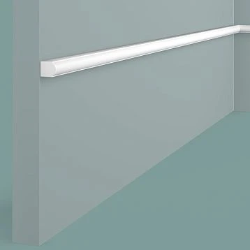
A wooden molding takes its final application shape after cutting. From a single stock strip, you get the sides of a frame, horizontal bands, or short inserts. Therefore, this type of decor has two separate characteristics: cross-section and original length.
The cross-section determines the width of the strip on the surface, the depth of the relief, and the fit to the base. The length limits continuous sections and affects the number of strips. Increasing the purchased meterage will not fix an incorrectly chosen profile: a molding that is too wide will still take up extra space on the facade.
When selecting Wooden moldings, determine the installation direction in advance. An asymmetrical profile has an inner and outer side. If one strip is flipped relative to the others, its relief will not continue the adjacent one, even when the corners are cut accurately.
Also mark all terminations. The profile may butt against another part, form a corner, end on an open section, or be closed with a specially selected element. A visible end requires a solution already on the drawing. After painting the entire composition, figuring out what to close it with is significantly less convenient.
The outer and inner dimensions of the frame differ
For a simple rectangular frame made of flat molding of constant width, first choose which contour the dimensions are based on. Suppose the outer overall size of the frame is 600 × 800 mm, and the width of each strip in the plane is 30 mm. Then the inner opening will be:
600 − 2 × 30 = 540 mm in width.
800 − 2 × 30 = 740 mm in height.
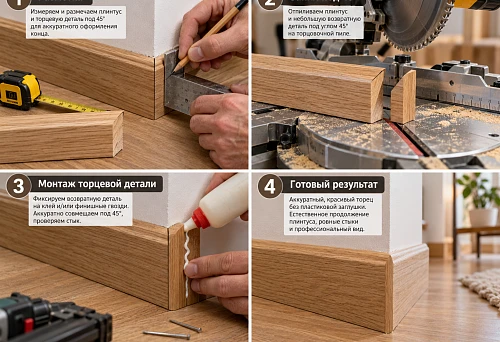
If the sides are joined with four standard 45-degree corner cuts in one plane, the lengths at the outer vertices will be two pieces of 600 mm and two of 800 mm. At the inner vertices, the same pieces will be shorter. One measurement method cannot be substituted for another.
For a complex cornice installed at an angle to the base, this flat scheme may not work. There, real installation planes and the corresponding method of constructing the joint are needed. Similarity of ornament does not make the cutting technique the same.
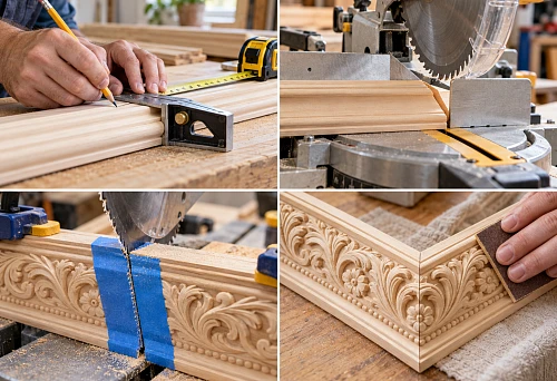
Before cutting a batch, assemble a test corner from suitable offcuts. Check the profile direction, relief alignment, joint tightness, and the visible frame line. If an error is found, adjust the setup and measurement method before processing all sides.
The number of commercial strips is determined by the cutting map
For two nominal frames of 600 × 800 mm, four sides of 600 mm and four of 800 mm are needed. The total length along the outer corners is 5600 mm. But what is ordered is not an abstract 5.6 meters, but a specific number of strips of available length.
If strips of 2400 mm are being considered, the preliminary distribution can be written as follows:
| Source strip | Required lengths along the outer corners | Their sum | Remainder before accounting for process losses |
|---|---|---|---|
| First | 800 + 800 + 600 mm | 2200 мм | 200 мм |
| Second | 800 + 800 + 600 mm | 2200 мм | 200 мм |
| Third | 600 + 600 mm | 1200 мм | 1200 мм |
This is a preliminary scheme, not a ready saw setup. From the remainder, material is also consumed by the cut, end trimming, allowances, and losses that depend on the direction of the corner cuts. The possibility of obtaining the parts is checked against the actual technology. If matching of a repeating ornament is provided for, its position on the original strip is also taken into account.
The production logic is clearly visible here: Wooden trim they are purchased with a ready-made cross-section, and the required lengths are obtained for a specific project. The craftsman's task is to determine in advance what exactly will come out of each commercial unit.
Molding decor is checked as part of the joint
A corner insert, a rosette at the intersection, and an end cap can change the entire cutting plan. If the profile meets the edge of the insert butt-jointed, its length is one value. If it goes under it, it is another. If it overlaps on top, the total protrusion must be checked.
Therefore Decor for Molding are selected together with the profile cross-section. Comparing width alone is not enough. The mating element may have a rebate that follows a specific shape, or a special adjoining section. A profile of similar size but a different cross-section can leave a gap or change the position of the part.
In the drawing, show the boundary of each component. A conventional thin line instead of the actual molding will not let you see how much space the joint occupies. This is especially noticeable on a small facade: a large corner element can shorten the straight section more than expected.
If the composition includes four corners, check whether all four orientations can be obtained. A single universal element sometimes works everywhere, while a directional one requires different versions. The quantity is counted only after laying out the corners with the face side toward the viewer.
The open end is also included in the schedule. An end cap, a short return of the profile to the base, or another termination adds its own operations and material. The chosen method should not mask a cutting error; it should be part of the original composition.
Different types of decor are counted in different units
A piece item is tied to a specific installation location. For it, the quantity is sufficient if the SKU, size, and finish are fully defined. A linear profile is first converted into a list of segments, then into the number of commercial strips.
| What is calculated | Unit of work | What must be separated |
|---|---|---|
| Central overlays | Pieces | Size options and material |
| Left and right overlays | Pieces of each option | Sides and pattern directions |
| Rosettes | Pieces | Dimensions, installation locations, orientation |
| Brackets | Pieces or mounting pairs | Pair composition and actual sales unit |
| Capitals and bases | Pieces per number of assemblies | Upper and lower elements, mating dimensions |
| Pilasters | Pieces with a specified length | Full and visible length, allowable trimming |
| Molding and linear trim | Cut pieces, then stock strips | Cross-section, original length, cutting map |
The entry "two brackets" differs from "two pairs." Before paying, check how the selected item is sold. The same applies to decorative sets: one set may include several elements, while a visually similar item may include only one piece.
A test sample is counted separately. If it will have different finishes, extra holes, or mounting tests, it cannot be included in the set quantity in advance. Any allowance for a possible replacement must also be justified separately, taking into account the fragility of the shape, the cost, and the lead time for obtaining another one.
In a small series, the quantity of piece decor is usually scaled directly: two rosettes per item yield ten for five items. Linear trim is more efficiently calculated for the entire series at once. A short leftover from the first frame may be suitable for the next one if the cross-section, material, and pattern requirements match. But a leftover is not considered suitable just because it is long enough: check the condition of the ends and the visible surface.
A full-size template and a three-dimensional fitting solve different tasks
A one-to-one scale template lets you check the contour without buying the whole set. It is placed against the facade, door leaf, panel, or frame, and the axis and adjacent elements are marked. This technique is especially useful for large overlays and repeating rosettes.
The printed scale must be checked with a ruler. If the program automatically reduced the drawing to fit the sheet margins, the neat paper contour will turn out smaller than the actual part. When building it yourself, mark a control dimension on the template and compare it with the selected version.
For a rosette, mark the center; for a directional overlay, mark the top and side; for a profile, mark the outer edge of the frame. An accidentally flipped template can create the false impression that the required mirrored shape is already there.
Flat paper does not show depth. After checking the contour, make a mockup of the protrusion from material of suitable thickness or use a real sample. On a moving facade, check the opening; near the handle, check hand movement; under the shelf, check the position of the front point of the bracket.
For a composite assembly, it is advisable to build the junction in three dimensions: part of the vertical, the capital, and a section of the upper profile. Here the outer contours may coincide in the frontal view but fail to align in depth. If you limit yourself to one view, this error can easily be carried over into the order for the entire batch.
A dry fit — checking without final fastening — includes more than just the placement of the decor. You need to make sure that the parts can be held and joined by the chosen method, that the tool can reach the fastening, and that adjacent elements do not interfere with each other. If the dry fit requires unforeseen force, determine the cause before applying glue or coating.
After approval, transfer the position to the drawing and apply clear marking on an acceptable area of the back side. A photo of the layout is useful as a supplement. It does not replace dimensions: the position of parts in the photo depends on perspective and the distance to the camera.
Choose the decor before calculating the related parts
In a joinery project, the elements that determine the dimensions of adjacent parts are chosen first. The capital defines the junction with the pilaster and the upper profile. The width of the molding determines the inner field of the frame. A deep overlay can change the opening conditions of the facade.
Therefore, the final cutting and drilling are performed after checking such positions. It is dangerous to draw large decor as a conventional blob: a later-selected article may extend beyond the field boundaries or block the necessary access.
Some solutions allow for later selection. For example, a small accent on a free, fixed surface, provided its permissible dimensions, material, and fastening method are determined in advance. But a color change is not always irrelevant either: a different type of finish may require different preparation and assembly sequence.
Checking priority is simple: will the drawing, hole, profile segment, or joint change if this element is replaced? If yes, the model is approved before the corresponding operation. If no, it can be selected later while preserving the already defined constraints.
If the task is still formulated only as "add decor to the door" or "decorate the frame," a useful article is on choosing wooden decor for joiners by product type. Once the zone is determined, proceed to precise geometry and mounting fit.
The wood species and finish are coordinated for the entire composition
Ready-made decorative solid wood parts are convenient because the complex relief is already formed, and the workshop can apply its own finish. However, identical treatment does not make different materials look visually identical. Under a clear finish, the species, grain pattern, and shade differences are especially noticeable.
Beech is often considered for opaque finishing when a less pronounced, coarse surface texture is required. Oak is chosen when the goal is to preserve a noticeable wood pattern. These are guidelines for selection, not a prohibition on other systems: oak can be painted, and beech can be finished with clear coatings. The result depends on the specific preparation and finish.
For each item, check the availability of the selected species and treatment option. In an overall composition, a single handle or overlay made of a different material may require its own color matching. If the mixing is intentional, it is shown on a sample; if it happened by accident, the same stain does not guarantee a match.
Look at how the part is oriented relative to the lighting. On adjacent carved surfaces, different grain and relief directions change the perception of tone. It is better to compare samples in a position close to the future installation, not only laid flat on a table.
Finishing and gluing cannot be specified in isolation from each other
For some compositions, it is more convenient to first assemble the prepared parts, then apply the overall covering finish. In other cases, part of the coating is applied before assembly, keeping the necessary contact areas in the condition required by the chosen adhesive. There is no single sequence for all substrates.
If the adhesive is designed for bonding clean wood, a layer of lacquer on the mounting area changes the conditions of its performance. If the composition allows gluing to a specific coating, the condition of that coating and the manufacturer's instructions must still be checked. Fixing time, surface preparation, and the possibility of adjustment are taken from the documentation for the specific material.
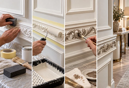
After a trial assembly, mark on the part the areas that need to be protected from the coating and the zones that will be difficult to reach with a brush or spray after installation. This is how the sequence becomes part of the product's technology. Painting "everything on all sides" without this check can add subsequent sanding in an awkward place.
Before starting work, compare the selected version with the information on the quality of wooden products и finishing and installation tips. Unpainted decor does not necessarily require the same level of finishing: the condition of the surface depends on the ordered variant and the requirements of your finishing system.
The sample must undergo exactly the future operation
A wood sample helps evaluate color and texture. A short profile — to examine the cross-section and test the finish. A whole capital or bracket is needed to check the joint. These samples answer different questions, so one cannot be substituted for another.
For a new item, first determine what remains unconfirmed. If the doubt concerns only color, a suitable material sample may be enough. If you need to check access to the fastening of a three-dimensional part, you will need the actual product or a reliable full-size mock-up of the assembly.
Section Product samples allows you to view the available options for preliminary selection. The possibility of ordering a full trial part in the required finish is clarified separately.
It is useful to accompany an approved sample with a short note:
- Which article number and size were used.
- What material the part is made of and what processing was ordered.
- To which surface and by what method it is attached.
- Which preparatory operations were performed.
- Which coating system was used and which result was accepted.
- What needs to be preserved for a repeat order.
If the trial revealed the need for trimming, drilling, or additional preparation, include these actions in the calculation for the entire batch. One successful result obtained after lengthy manual adjustment does not yet confirm the convenience of serial assembly. It is necessary to understand whether it can be repeated in the same way for the remaining items.
After approval, keep the sample available for comparison. A photograph does not convey the exact gloss, depth of texture, and condition of the contact surface. On the next order, a physical sample helps verify these properties together with the recorded dimensions.
Create a decorative product schedule
The schedule links the selected model to the installation location and subsequent work. Entries like "nice socket" or "molding as in the picture" are unsuitable for ordering. They do not allow unambiguous determination of size, material, and finish, especially if someone else handles procurement.
Each item must have its own designation on the drawing and the full supplier article number. The internal number helps locate the installation position; the article number is used to order the product. These two designations serve different purposes.
Material, dimensions, processing option, quantity, and installation operation are entered in separate columns or notes. For linear moldings, the original length and cutting plan are retained. For mirrored decor, the left and right sides are recorded separately.
Below is an example of how to format several rows. The quantities are illustrative; the table shows the method of recording, not a ready compatible set for a single product.
| Position on the drawing | Model | Selected dimensions in mm | Quantity | Additional entry |
|---|---|---|---|---|
| RZ-01 | R-084 | 45 × 45 × 13 | 4 pcs. | Material, installation axes, finish option |
| KR-01 | KR-044 | 80 × 50 × 20 | 2 pcs. | Purpose, junction section, fastening method |
| KP-01 | KL-004.02 | 68 × 82 × 32 × 19 × 54 | 2 pcs. | Mating vertical and dimensions according to the drawing |
To turn such an example into an order, you need to fill in additional details and confirm them on the project. A single article number often combines several sizes and wood species. Therefore, the photo and model name do not replace a full description of the finish.
Long profiles are more conveniently placed in a separate part of the list. It will contain two linked entries: the purchased strips and the segments obtained from them. The purchase line indicates the number of commercial units; the cutting map shows the position of each segment in the future composition. This way, the number of strips is not mixed up with the number of frame sides.
If the project has changed, update both entries. Increasing the facade width changes the profile lengths, the inner field, and sometimes the size of the central overlay. An old list with a new drawing becomes an independent source of errors.
For regular orders, also save the finish approval date and the approved sample. The possibility of reordering the required parts and conditions for manufacturers are clarified according to the specific list. The article number helps repeat the selection, but does not guarantee unchanged availability or lead times.
Mistakes in selecting and installing joinery decor
Most problems appear at the boundary between the selected part and the rest of the product. The decoration itself may be of good quality, but not suit the surface, the size of the field, or the assembly sequence.
| Mistake | Why it occurs | Consequence | How to prevent |
|---|---|---|---|
| Choosing only by the front photo | The volume and the back surface remain unnoticed | Gaps, extra protrusion, mismatch with the base | Check the drawing, side view, and joint |
| Marking from several random edges | Each element is set separately | The row loses its common axis | Assign a single reference base |
| Ordering identical parts instead of a mirrored pair | Rotation is mistaken for reflection | The ornament is oriented in the wrong direction | Lay out the entire set and separate the versions |
| Selecting a capital by overall width only | Bottom and top joints are not taken into account | An unintended step or mismatch appears | Build a composite assembly with real dimensions |
| Converting total square footage directly into purchasing | No cutting map has been created | The required long sections do not come out | Lay out the parts on stock boards before ordering |
| Full finishing before checking joints | The sequence is chosen for ease of painting | Requires cleaning or the coating gets damaged during fitting | First perform a trial fit and approve the technique |
| Pressure against a protruding relief | The fixing point is not prepared | Marks, damage to thin areas | Check the retention method on a trial assembly |
A separate mistake is to treat any noticeable gap as a task for glue or filler. If the cause is an incompatible cross-section, an incorrect cut, or an unsuitable surface, the geometry is corrected first. Filling may hide the external symptom, but it will not restore proper mating or ensure the required performance of the joint.
For a series, it is useful to check the first assembled unit before starting the rest. If, after its installation, the template, offset, or fastening order has to be changed, the changes are immediately transferred to the drawing and the work record. Otherwise, the next part will again be manufactured according to the original version.
When the selected decorative element is better not to install
It is worth refusing the purchase if the part overlaps the working gap, blocks the movement of the panel, prevents opening, or removes access to the necessary fastening. Such limitations cannot be corrected only by choosing a color and stronger pressure.
Sometimes it is enough to reduce the size or change the decor group. Instead of a long overlay, you can choose a compact rosette; instead of a deep protruding element, a flatter shape. But the replacement undergoes the same fit check. A smaller overall size alone does not yet confirm compatibility.
A purchase is also questionable if installation would require substantially reworking an already formed relief. Trimming both sides of a capital or removing most of the overlay ornament means that the original shape was probably chosen poorly. For a special junction, consider another model, a redesign of the composition, or custom fabrication with agreed dimensions.
Sometimes additional decor is not needed at all. An expressive facade profile or wood grain is already enough, while a new element reduces the free field and makes the furniture harder to use. In such a project, an unfilled area of the surface may be a more precise solution than another overlay.
Additional questions about using ready-made decor
Can a flat overlay be installed on a radiused surface
Only if its mounting geometry and fastening method suit such a base. Pressing it against a convex surface may provide contact only over a small area. You should not expect that a rigid ready-made part can be safely pulled along a radius. A suitable shape, agreed treatment of the back side, or another designated junction is needed; the possibility of modification is checked before purchase.
Is interior wooden decor suitable for outdoor use
The intended purpose of the specific product, its construction, and its protection system must permit such conditions. Choosing oak instead of beech does not by itself turn an interior overlay into an exterior one. For outdoor use, exposure to moisture, connection details, coating, and maintenance are agreed separately. If the conditions of use are not confirmed, the interior installation scheme should not be transferred outdoors.
Can only the missing element be ordered after assembly
The possibility depends on the availability of the model and finish. For an exact match, keep the item code, dimensions, material, and finish sample. With a transparent coating, the new part may differ in texture and shade even in the same species. Therefore, visible paired elements are best agreed together, and a small repair reserve should be assessed during the initial purchase.
Where to buy joinery decorative elements
Start your selection with the geometry already defined: an overlay decorative piece for a free surface, a rosette for a focal accent, a three-dimensional element for a proven spatial junction, a capital with a coordinated vertical, a profile with calculated segments. This kind of entry gives the catalog a clear task.
At STAVROS you can choose solid wood products and other wooden components for joinery projects. Check the material for each item: the general section also includes MDF products. If you need to buy Carved wooden decoration, match the selected overlays, rosettes, brackets, and capitals against the actual installation surfaces.
Before payment, verify the item codes, finishes, quantity, and units of sale. For long linear moldings, check the cutting plan; for directional decor, check the sides; for composite elements, check the joint dimensions. The lead time and payment and delivery terms include them in the schedule before the general finishing stage.
Ready-made joinery decorative elements become convenient production components when the craftsman knows their place and method of use in advance. In a completed specification, next to each model there is not only the quantity but also a clear operation: mark along the axis, join with the selected profile, cut according to the plan, test-fit to the base, or assemble into a coordinated junction.