Article Contents:
- First, locate and classify the expansion joint
- Why the expansion joint must be located before ordering mouldings
- What an expansion joint is in the context of interior finishing
- The buyer discovers the conflict but does not design the detail
- The expansion joint map must work across the full height of the interior
- Skirting at a working joint: the long line is split into two independent parts
- Wall molding at an expansion joint requires architectural redesign of the pattern
- The horizontal molding band should be divided by zones in the schedule
- The ceiling cornice is also subject to the structural boundary
- A single vertical expansion joint is best treated as a unified interior axis
- A horizontal structural joint creates a different procurement task
- Linear trim next to the joint and linear trim across the joint are different scenarios
- Typical floors should be calculated with a typical seam joint
- The seam between buildings should be reflected in procurement as the boundary between two requirements
- The wall panel and molding at the seam should be handled by a single system
- A door next to a seam creates a critical short section
- A seam next to an internal or external corner reduces cutting freedom
- After the joint is approved, the old specification must be fully recalculated in the affected area
- The special parts map should exist separately from the total meterage
- Special short parts can reduce waste if they are known in advance
- A wholesale order must contain already approved final lengths
- Delivery queues should be divided by building blocks and sections
- Acceptance of special parts should be stricter than for a regular batch
- The installer must see the design solution for the expansion joint
- If the actual position of the joint does not match the architectural elevation, the set cannot be trimmed "on site" without recalculation
- Practical example: a hotel corridor with one structural axis across eight floors
- Why three independent solutions at one joint create visual chaos
- How to calculate the reserve for special parts at expansion joints
- How to submit a commercial request to the supplier after joint coordination
- If the same item code is used on both sides of the joint, the overall commercial total can still be summed up
- Price per meter poorly reflects the cost of an assembly at an expansion joint
- How to verify that a line truly requires a separate assembly and is not just an ordinary decorative joint
- Multiple expansion joints must be coded separately, even if the assembly looks visually identical
- A change to the design assembly after ordering must be assessed through its consequences for all three types of trim profiles
- Practical calculation: the same line before and after the joint appears
- When a new assembly reduces the number of long joints
- When it's better not to buy special pre-prepared parts in advance
- Commercial interlinking should guide the user through the task stage
- 15 mistakes when coordinating linear trim with expansion joints
- Checklist before wholesale purchasing
- Final algorithm for recalculating linear trim at expansion joints
- What the final line of a special part should look like

On a large project, the interior is often designed as a continuous system: the baseboard runs along a long corridor, the wall molding forms a single horizontal band, and the ceiling cornice continues the upper line through the lobby. On the architectural elevation, these three elements look like independent decorative strips. But the building structure may contain an expansion joint that runs through the same corridor from floor to ceiling.
This is precisely where wholesale moulded products cannot be calculated by total length alone. If a structural working boundary divides two parts of a building, the decorative profile cannot automatically be turned into a rigid bridge between them just for the sake of visual continuity. The specific junction must be approved by the project. After that, not only the installation components change, but also the procurement math: one continuous run splits into two parts, ends appear, short special pieces, separate codes, a new cutting plan, and a different requirement for the source strips.
The central rule for the buyer can be stated simply: the expansion joint must make it into the finishing and specification documentation before the final lengths of skirting, moulding, and cornice are calculated. The buyer does not design the structural joint and does not choose how it is bridged. Their task is to detect the intersection, request the approved junction, turn the architect's and engineer's solution into specific finished components, and only then release the wholesale order.
JOINT MAP → INTERSECTION WITH SKIRTING / MOULDING / CORNICE → APPROVED JUNCTION → SPLITTING OF CONTINUOUS LINES → SPECIAL ENDS → NEW FINISHED LENGTHS → CUTTING PLAN → NUMBER OF STRIPS → SEQUENCE → WHOLESALE ORDER
STAVROS already has a narrow article about the carved profile KPU-105 on a slatted wall with an expansion joint. It covers a specific product 1000 mm long and a specific decorative line. This article has a different task: how one structural joint simultaneously affects linear products wholesale across the entire large project — the skirting, wall mouldings, and upper cornices, which are at different heights but encounter the same structural boundary.

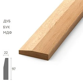
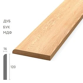
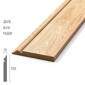
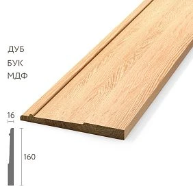
First, find and classify the expansion joint




Why the expansion joint must be found before ordering mouldings
Before information about the joint appears, the procurement list may contain one long run. For example:
3rd floor corridor / skirting PLT-A / 5800 mm.
After coordination with the structural design, it becomes clear that a working expansion joint passes through the wall. The design specifies that the wooden skirting board must end on one side and start anew on the other, preserving the structural independence of the parts. Then the old line no longer corresponds to the design.
Instead, the following appear:
- left part of the skirting board;
- special end piece on the left;
- expansion joint zone;
- special end piece on the right;
- right part of the skirting board.
The same happens with the wall moulding and ceiling cornice. If the joint is vertical and runs the full height, one structural fact can simultaneously change three separate bills of materials.
Why you need to know this before placing a wholesale order. After the detail is approved, the finished lengths change. Consequently, the cutting plan for the source strips changes, the number of usable offcuts changes, and sometimes the number of stock-keeping units itself changes. If the linear trim has already been ordered along the old continuous route, some parts will have to be cut on site, and there may not be enough special short elements or neat end pieces.
Serial projects are especially critical: hotels, business centres, residential complexes and public buildings. If the same joint repeats on eight floors, an error in one layout drawing turns into eight identical errors.
Our factory also produces:


What is an expansion joint in the context of interior finishing
This article does not replace a structural design and does not explain building calculations. For the procurement specialist, only the following matters: an expansion joint is a boundary specified by the design, associated with possible relative movement of parts of the structure or finishing system. Therefore, it cannot automatically be considered an ordinary decorative gap.
Manufacturers of specialized expansion joint systems design their profiles specifically so that they can accommodate movement. Finishing systems also use the principle that movement of the substrate must be accounted for in the finish layer. This leads to a safe procurement logic: if a line is confirmed as a working joint, a decorative wooden profile should not be arbitrarily designated as an element that rigidly connects both sides.
The purchaser does not determine the working width of the joint, permissible movements, type of filling, or method of fastening. These parameters belong to the design detail. The purchaser receives an approved solution and reflects it in the lengths and quantities of linear meters.
An ordinary decorative seam and a working expansion joint are not the same thing
An ordinary seam may occur between two sheets, panels, sections of finishing, or at the edge of a decorative system. It may have no movement compensation function at all. In such a place, the design is entitled to specify a continuous molding or another decorative cover.
A working expansion joint has a different role. Therefore, the visual similarity of two lines proves nothing. If a joint is marked on the plan, there is a specialized profile, elastic filling, or a separate structural instruction, it cannot be turned into an ordinary seam without verification.
Practical conclusion: before calculating linear meters, one must not guess the type of line from a photograph, but obtain confirmation from the designer or from the working documentation.
Get Consultation
The purchaser identifies a conflict but does not design the detail
In procurement work, there is easily a temptation to resolve the issue “on site.” For example, the architect did not show the detail, but the molding visually should continue. It seems logical to run one long strip across the joint and get a beautiful continuous line.
This is exactly what should not be done without a design solution.
The purchaser can:
- note that the profile crosses the joint;
- specify the article number and cross-section of the decorative element;
- show the finished lengths on the left and right;
- record which rooms and floors are affected;
- request the detail from the architect or structural engineer;
- after approval, recalculate the specification.
But they must not independently decide whether the joint can be covered with a single strip, what gap to leave, what to fill it with, and how to attach the profile to both sides.
Why this matters commercially. The mistake may not be in the number of meters, but in the scheme itself. A perfectly calculated continuous molding remains an incorrect order if the structural design requires separate sections.
The joint map must cover the skirting board, moulding and cornice
The expansion joint map must work across the full height of the interior
A single mark on the plan is not enough. The skirting board is at floor level, the moulding may run at a height of 900–1200 mm, and the cornice is under the ceiling. A single vertical joint can cross all three levels.
Therefore, a conflict map is useful:
| Zone | Element | Article | Does the joint intersect? | Is the detail approved? | Node code |
|---|---|---|---|---|---|
| 3rd floor corridor | Baseboard | PLT-A | Yes | No | EJ-01 |
| 3rd floor corridor | Molding | MLD-B | Yes | No | EJ-01 |
| 3rd floor corridor | Cornice | KZ-C | Yes | Yes | EJ-01 |
| Hall | Baseboard | PLT-D | No | — | — |
Such a table immediately shows where the procurement specification is not yet ready. As long as “detail not approved” appears next to PLT-A and MLD-B, the final lengths of these items cannot be considered closed.
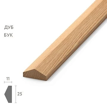
A general catalogue is used to select the profiles themselves wooden trimBut the seam map must exist separately from the product catalog and link the profile to a specific structural axis of the object.
Skirting at the working seam
Skirting at the working seam: the long line is split into two independent parts
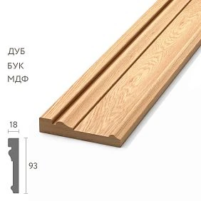
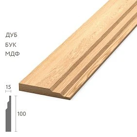
The floor skirting is most often the first to reveal the conflict, because it runs along a long continuous line along the wall. On site, there may be a corridor of 20–30 m where the designer expects a single wooden strip. A structural seam splits this line into two parts.
Before coordination, the schedule may contain:
Corridor K-01 / PLT-A / 5800 mm.
After the detail is approved:
PLT-A / left part / 2350 mm / end DS-01L.
PLT-A / right part / 1180 mm / end DS-01R.
The seam itself is not included in the finished length of the skirting as a section that the decorative strip must cover. If the project provides for a specialized insert or other treatment, it is listed as a separate structural line and is not considered part of the wooden skirting.
Why a continuous plank across a joint may be incorrect logic
If the two sides of the base need to be able to move relative to each other, one rigidly fixed wooden part on both sides becomes an unnecessary bridge. How critical this is for a specific building is determined by the design. The procurement article does not provide a universal structural recommendation; it establishes that continuity cannot be considered the default norm.
What design solution options may exist
Depending on the architecture and the specialized system, the designer may provide:
- an open gap;
- two independent ends;
- a special expansion profile;
- a decorative insert designed to accommodate movement of the assembly;
- separate fastening of the two parts of the skirting board;
- another solution confirmed by the design.
Any of these options affects procurement. Before the decision, it was "one 5.8 m line." After the decision — two or more parts, additional ends, and a new cutting plan.
If the project procures Baseboard and other types of trim require special transportation conditions. across several floors, special sections at the joint should be issued as a separate code rather than hoping that installers will cut it the same way every time.
Molding and framed compositions at the joint
Wall molding at an expansion joint requires an architectural redesign of the pattern
Molding is more difficult than baseboard not structurally, but visually. It often forms a noticeable horizontal line, rectangular frames, or panel trim. If the joint runs through the middle of such a composition, a simple break can ruin the pattern.
But this does not mean that the molding should automatically be carried across the joint. On the contrary: first the architect decides how the composition should work next to the structural boundary, then the procurement specialist receives the new parts.
If the joint runs through the frame
There are several architectural scenarios:
- change the dimensions of the frame so that the joint falls between the modules;
- split one large frame into two independent compositions;
- preserve a technical gap within the pattern;
- use a separate vertical element or another approved joint;
- omit the frame in this specific area.
The purchaser does not choose which option looks better. But after approval, they must recalculate the number of verticals, horizontals, and corners.
Before the change, a standard frame could be:
1500 × 900 mm → 2 verticals of 1500 + 2 horizontals of 900.
After splitting, the seam may produce:
frame M-1L + technical gap + frame M-1R.
This is already a different set of parts. If not recalculated, the order will include extra long horizontals and lack short end pieces.
A special frame is best coded separately
For example:
M-1 — standard frame.
M-DS-1 — frame at the expansion joint.
If the joint repeats on eight floors, procurement gets a clear formula:
M-DS-1 × 8.
This way, the exception stops being a “standard number error” and becomes a normal design module.
For product selection Moldings in Bulk they remain a separate branch. In the new article, what matters is not the choice of a specific profile, but how the structural joint changes its quantity and lengths.
The horizontal molding band should be divided in the schedule by zones
The simplest case is a long horizontal molding along a corridor. On the architectural elevation, it reads as a single 62 m line. The structural joint may be located approximately in the middle.
Bad entry:
Corridor molding — 62 m.
Working:
| Code | Zone | Length | Ending | Note |
|---|---|---|---|---|
| MP-01L | To DS-01 | As per project | DS-01L | Left side |
| EJ-01 | Seam | By node | — | not wooden molding |
| MP-01P | After DS-01 | As per project | DS-01P | Right side |
The advantage of this structure is that when a seam changes, only the affected module is recalculated. The overall corridor molding does not need to be restored from old drawings.
Why equal height matters for visual continuity
Physical continuity and visual continuity are not the same thing. If the design includes a break, the left and right moldings can remain at the same level and have the same profile and finish. The eye continues to perceive the composition as a single line, even though the parts are structurally independent.
This is a useful principle for design: a technical pause does not necessarily look accidental if its position and ends are planned in advance.
Ceiling cornice and structural boundary
The ceiling cornice is also subject to the structural boundary
A cornice at the ceiling can create an even more noticeable problem, because relief and side light make the break more visible. But decorative expressiveness does not cancel out the design detail.
Before ordering cornices wholesale for an area with an expansion joint, you need to know:
- the exact axis of the joint;
- the cornice cross-section;
- the position of the cornice relative to the ceiling profile of the joint;
- is a continuous decorative line per the design acceptable;
- how the terminations on the left and right are finished;
- is there a special insert or profile;
- what finished lengths result after splitting.
Why the cornice is especially sensitive to a gap. On a complex profile, shadow emphasizes the geometry. If one termination is cut 20 mm beyond the axis and the other is closer, the offset is noticeable. Therefore, it is useful to tie both sides to a single structural axis DS-01.
If the design includes a separate profile in the joint area, the wooden cornice is brought to it as to a design boundary, rather than trying to replace it.
A single vertical expansion joint is best resolved as a unified interior axis
Let's imagine a hotel corridor. DS-01 runs vertically across the entire wall. At three heights it is intersected by:
- floor skirting PLT-A;
- wall molding MLD-B;
- ceiling cornice KZ-C.
If each element is handled separately, it is easy to end up with visual chaos: the skirting is broken at one point, the molding is 30 mm off to the side, and the cornice runs continuously through. Formally, the three solutions may each be "correct," but together they look accidental.
It is much clearer to use a single vertical axis:
DSH-01 = a unified structural boundary from floor to ceiling.
| Level | Element | Special part code | Reference |
|---|---|---|---|
| Floor | PLT-A | P-DSH-01 | DSH-01 axis |
| Wall | MLD-B | M-DSH-01 | DSH-01 axis |
| Ceiling | KZ-C | K-DSH-01 | DSH-01 axis |
The architect can still choose different end geometries at each level. But all three solutions are subordinate to a single axis and coordinate easily.
Horizontal joints and profiles running parallel to the joint
A horizontal structural joint creates a different procurement task
Not every joint is vertical. A horizontal boundary may run along a wall or within a panel system. In this case, the floor skirting may not cross the joint at all, while the wall molding may cross it or run parallel to it.
Therefore, the DS-01 scheme for a vertical joint cannot be automatically transferred to a horizontal scenario.
Working check:
- which decorative lines physically cross the joint;
- which run parallel;
- what substrate each line has;
- whether there are fastening restrictions near the joint;
- whether the joint must remain accessible for inspection.
If the molding is located above or below the joint and does not cross it, the risk of a rigid bridge may be absent. But the fastening method must still correspond to the base design. The procurement article should not invent a universal adhesive assembly.
Trim near the joint and trim across the joint are different scenarios
The narrow STAVROS article on KPU-105 shows this difference on a specific slatted wall. If the decorative profile runs across the working joint, the question of dividing the line arises. If it is located nearby and does not cross the joint, the task is different: check the distance, the base, and access to the structural assembly.
For a large project, it is useful to add a "relation to joint" field to the map:
| Article | Zone | Relation to expansion joint | Action |
|---|---|---|---|
| PLT-A | Corridor | crosses | design assembly required |
| MLD-B | Panel | parallel | check base and access |
| KZ-C | Hall | crosses | divide according to design |
This prevents the automatic application of a single solution to all profiles adjacent to the joint.
Why fasteners and adhesive cannot be determined from procurement logic
If one strip must be attached simultaneously to two movable bases, this becomes a design question. The procurement specialist can report that the profile crosses the joint and show its cross-section, but must not independently assign the method of adhesive or mechanical fastening.
Typical floors, buildings, and repeated assemblies
Typical floors should be calculated with a typical joint assembly
If a hotel has eight identical floors and the expansion joint runs along the same location in the corridor, the project gains a significant advantage: the special assembly can be developed once and repeated.
For example:
EJ-01 / floors 2–9 / skirting PLT-A / molding MLD-B / cornice KZ-C.
On each floor, the following are repeated:
- two skirting ends;
- two molding band ends;
- two cornice ends;
- corresponding short sections on the left and right;
- identical alignment to the seam axis.
Result: instead of eight independent improvisations by installers, there is one coordinated standard module multiplied by eight floors.
Why this matters for wholesale kit assembly
Special parts can be identified in advance in the bill of materials and linked to a specific sequence. For example:
| Code | Per 1 floor | Floors | Total quantity |
|---|---|---|---|
| P-DSH-01L | 1 | 8 | 8 |
| P-DSH-01R | 1 | 8 | 8 |
| M-DSH-01L | 1 | 8 | 8 |
| M-DSH-01R | 1 | 8 | 8 |
| K-DSH-01L | 1 | 8 | 8 |
| K-DSH-01R | 1 | 8 | 8 |
Against thousands of linear meters, this is a small volume. But it is precisely these short special parts that are most often lost if the order is based only on the total linear meters.
The seam between building sections should be reflected in procurement as the boundary between two requirements
On large projects, a single interior line may visually continue from building section A into building section B. For example, a long corridor, public lobby, or restaurant occupies two structural sections. The architect may want a unified style, but structurally these are already two parts of the building.
For procurement, it is safer to count:
building section A → separate requirement;
building section B → separate requirement.
If the same SKU is used on both sides, the overall commercial total can be obtained after separate calculations. But initially, a single line "corridor skirting — 46 m" across the boundary between the units is too crude.
What this separation provides
- clear origin of the volume;
- separate cutting;
- separate delivery queues;
- accurate reorder by unit;
- control of special finishes at the seam;
- protection against mixing materials from two sections.
If purchased wholesale purchase of building materials for the entire project, separation by units does not prevent obtaining an overall total by SKU. It only preserves the project structure until the final stage.
The wall panel and the molding at the joint must be resolved as a single system
If the molding is part of the wall panel, you cannot first order the molding and then separately decide where the panel will end. The joint affects the substrate, the panel, the decorative profile, and the visible termination all at once.
Correct sequence:
- determine the axis of the expansion joint;
- approve how the panel system meets it;
- fix the termination of the panel on the left and right;
- agree on the position of the molding;
- only after that, calculate the parts.
If the panel ends 20 mm earlier than the buyer expected, the horizontal and vertical parts of the frame also change. For hundreds of repeating modules, this is a significant volume.
Why you cannot automatically assume "1200 mm panel + 1200 mm molding"
The molding may run along the outer contour of the panel, along the centerline, or along another design dimension. The joint itself may require a free margin. Therefore, the finished length of the molding is determined by the approved geometry, not by the nominal width of the panel.
Doors, corners and other critical short sections
A door next to a seam creates a critical short section
A working seam is rarely located in a perfectly free spot. It may be next to a door casing, a corner, a niche or built-in furniture.
Let's imagine:
- axis ДШ-01;
- to its right — a door casing;
- between the seam and the casing there remains 620 mm of wall;
- a floor skirting board runs along the wall.
Formally, this is a short piece of 620 mm. But it has two fixed boundaries at once: a special end at the seam and an abutment to the casing. The installer can no longer "shift the cut" by 30–50 mm for the convenience of cutting.
This element is worth highlighting:
П-ДШ-ДВ-01 / 620 mm / 8 pcs.
If a part repeats on eight floors, it becomes a separate cutting group.
Why a short special part is not equal to a random offcut
A 650 mm offcut may theoretically fit in length, but you need to check the quality of both ends, the orientation of the profile, and the ability to form the required termination and junction. That is why a special part uses the remainder only after verification, not automatically.
A seam next to an internal or external corner reduces cutting freedom
If a short section remains between the corner and the seam, procurement immediately gets two fixed points. For example:
internal corner → 430 mm → ДШ-01.
Such a part cannot be arbitrarily increased or decreased if both boundaries are already approved. On site, it is easy to lose it among the total meterage because 430 mm seems like a trifle.
But 20 identical parts are 8.6 m of finished material and 20 specific assemblies.
The external corner is even more demanding
At an external corner, quality is visible from two planes at once. If the seam is nearby, the short segment gets complex processing on one side and a special termination on the other. It is better to account for such an element in advance as critical, rather than leaving it “for filling from leftovers” without control.
After the assembly is approved, the specification and cutting layout are recalculated
After the assembly is approved, the old specification must be fully recalculated in the affected area
Working order:
- apply all confirmed expansion joints;
- determine which profiles intersect each joint;
- obtain the approved architectural and structural assembly;
- split previously continuous lines;
- add special end caps and short parts;
- update finished lengths;
- rebuild the cutting layout;
- recalculate the number of source strips;
- update the reserve;
- only after that, release the order.
You cannot keep the old total linear meters and add “a little for special parts.” After splitting, part of a long strip may turn into two short elements that are cut differently.
Example: 3530 mm turns into 2350 + 1180 mm
Before the split, the purchaser saw one section of 3530 mm. After approval:
- left part — 2350 mm;
- right part — 1180 mm.
For a 2400 mm strip, the left part almost entirely occupies a separate item, while the right part can be combined with another short component. That is, the total meters have not changed, but the purchasing cut has changed noticeably.
The special parts map must exist separately from the total linear meters
After coordination, it is useful to divide the parts into groups:
| Group | Example | How to use |
|---|---|---|
| Standard | standard wall | Basic cutting |
| At the expansion joint | P-DSH-01 | special end |
| Joint + corner | P-ДШ-УГ-01 | critical short segment |
| Joint + door | P-ДШ-ДВ-01 | two fixed boundaries |
| Joint + panel | M-ДШ-ПН-01 | depends on the panel layout |
This grouping is more useful than the general "non-standard" field. It shows why a specific part has a separate length.
Special short parts can reduce waste if they are known in advance
An expansion joint does not necessarily only increase waste. After splitting a long line, short parts may appear that are convenient to obtain from the remnants of other standard sections.
For example:
- after a 1700 mm part from a 2400 mm plank, about 700 mm remains before technological accounting;
- the special segment P-DSh-DV-01 has 620 mm;
- the remainder can potentially be used for it.
If there are eight such parts and eight such remnants, the total purchased linear meters may hardly increase. But this is only visible after the special part has been included in the bill of materials.
Why all offcuts cannot be considered waste in advance
First, a complete set of lengths for the entire object or installation stage is formed. Then long and critical parts are distributed across the source planks, after which the remnants are matched with short standard and special elements.
That is why building materials at wholesale prices you need to compare using the actual cutting map, not a simple waste percentage.
A wholesale order must contain already approved final lengths
The supplier does not necessarily need to receive the entire structural design of the building. But the linear trim specification must take into account the result of coordination.
Bad:
PLT-A / corridor / 62 m.
Better:
| Code | Article | Zone | Length | Quantity | Note |
|---|---|---|---|---|---|
| P-01 | PLT-A | To DS-01 | 2350 | 8 | end of DSh-01L |
| P-ДШ-ДВ-01 | PLT-A | After DS-01 | 620 | 8 | To the trim |
This way the supplier receives already finalized geometry and can correctly calculate the initial planks.
If used Decorative wooden trim multiple SKUs, each item still remains a separate product line. A shared category does not cancel out differences in profile and length.
Queues, acceptance, and installation handover
Delivery queues must be divided by building blocks and sections
If the first section is on one side of the expansion joint and the second is on the other, they should not be automatically mixed just because the profile is the same.
The specification can store:
- building;
- section;
- floor;
- joint axis;
- delivery sequence.
This also helps with repeat orders. If a year later the skirting board in building B near expansion joint 02 is damaged, it is immediately clear which structural part the component belongs to and which version of the assembly was used.
For the B2B process delivery of finishing materials must preserve this structure until unloading: item code, zone, floor, special part code, and quantity.
Acceptance of special parts must be stricter than for a regular batch
For a standard long plank, it is sufficient to check the item code, material, finish, and quality. For a special part at an expansion joint, the following are additionally important:
- exact length;
- orientation, if the left and right elements differ;
- type of end;
- zone code;
- compliance with the current revision of the specification.
If the supplier delivers whole planks and the special parts are cut on site, acceptance checks that there is a sufficient stock of material and that the source items are marked.
Why the left and right parts may differ
A complex profile's visible end may have an orientation. Even with the same length, two elements are not always interchangeable after pre-processing. If the project includes mirrored ends, L/R codes prevent confusion.
The installer must see the design solution for the expansion joint
It is not enough to rely on the instruction "the skirting and cornice are in the warehouse." The installer must understand exactly where the decorative system is interrupted and which parts belong to the DS-01 axis.
It is especially important to prohibit unauthorized "cosmetic touch-ups" if the gap looks visually unattractive. The working function of the joint is more important than the desire to hide a technical line with a random wooden strip.
Minimum installation package:
- plan with the joint axis;
- approved detail;
- codes for special parts;
- positioning of the skirting, moulding, and cornice;
- current version of the specification.
If the actual position of the seam has changed
If the actual position of the seam does not match the architectural layout, the set cannot be cut "on site" without recalculation
On a construction site, an unpleasant scenario occurs: in the working layout, the axis of DS-01 is shown at one elevation, while the actual boundary after opening up the finish is 40–80 mm to the side. For an ordinary long wall, such a displacement seems small. For special parts near the seam, it can completely change the cutting plan.
Let's imagine that according to the design, the left part of the skirting board should be 2350 mm, but the actual axis has shifted by 60 mm. The new finished length is 2290 or 2410 mm, depending on the direction of displacement. In the first case, the original 2400 mm strip still fits. In the second, a solid part made from 2400 mm is no longer possible.
Therefore, you cannot simply cut the finished set "as it turned out." You need to:
- record the actual position of the seam;
- verify it with the designer;
- update the lengths of all intersecting profiles;
- recalculate only the affected parts;
- check which original strips have already been manufactured or shipped;
- issue a new revision of the specification.
If the offset affects one floor, the problem is local. If the structural axis is systematically shifted across the entire building, the previous standard DS-01 kit no longer applies.
Practical example of a hotel corridor
Practical example: a hotel corridor with one structural axis across eight floors
Let's take a hypothetical project. On each of the eight standard floors, a vertical expansion joint runs across the corridor. It is intersected by:
- floor skirting PLT-A;
- horizontal molding MLD-B;
- ceiling cornice KZ-C.
Before coordination on one floor, the schedule contains:
| Element | Old finish line |
|---|---|
| PLT-A | 5800 мм |
| MLD-B | 6200 мм |
| KZ-C | 5700 мм |
The architect and structural engineer approve DS-01 as a single vertical axis. After the decision, the lines are split.
| Element | Left part | Right part | Special parts |
|---|---|---|---|
| PLT-A | 2350 мм | 3380 мм | 2 endings |
| MLD-B | 2540 мм | 3590 мм | 2 endings |
| KZ-C | 2250 мм | 3380 мм | 2 endings |
Dimensions are for demonstration. The seam itself and the required free margin are not included in the wooden linear trim table as decorative length.
How PLT-A purchasing changes
The old 5800 mm line still required several source planks, but the joint locations could be chosen more freely. After the introduction of ДШ-01, the 2350 mm length becomes a critical separate part. If the commercial length of PLT-A is 2400 mm, a separate plank is almost guaranteed to be needed for it. The 3380 mm right part requires two or more parts with separate joint logic.
How MLD-B changes
The 2540 mm left part may be larger than the commercial length of a specific molding. Previously, the buyer could shift the internal joint within the entire 6200 mm line. Now the structural axis fixes the right boundary of the left part, and the choice of joint location becomes more limited.
How KZ-C changes
The 2250 mm left part fits conveniently into a 2400 mm plank. But the 3380 mm right section must be assembled separately. If the cornice is large and the joint is visible, its position is coordinated architecturally.
What happens across eight floors
Each special element is multiplied by eight. Procurement receives:
- 8 special left sections PLT-A;
- 8 right sections PLT-A;
- 8 left and 8 right parts MLD-B;
- 8 left and 8 right parts KZ-C;
- 16 design terminations of each profile type, if they are actually provided by the assembly.
One structural axis creates a repeatable procurement module. This is the practical value of early coordination.
Why three independent solutions at one joint produce visual chaos
Let's imagine the reverse scenario. The skirting crew sees the joint and leaves a gap along the axis. The moulding installer wants to preserve a clean horizontal line and shifts the termination 30 mm toward the nearest panel edge. The cornice crew receives no information about the joint at all and runs the profile continuously.
As a result, one constructive line reads differently at three levels:
- the skirting is broken along the axis;
- the molding — with an offset;
- the cornice — without a break.
Even if each installer acted carefully, the overall interior
Reserve, wholesale order and commercial outcome
How to calculate the reserve for special parts at expansion joints
You cannot automatically add 10% to the total linear footage and assume that special nodes are protected by the reserve. For a short part at a joint, it is more useful to understand whether it can be restored from a whole plank of a standard article.
There are two approaches.
Product reserve
Whole planks PLT-A, MLD-B and KZ-C are stored. If a special part is damaged, it is cut again to the approved size.
Advantage — the reserve is universal within a single article. Disadvantage — after a few years, documentation with the exact length and processing is required.
Complete reserve
Pre-prepared special parts P-DSH-01L, P-DSH-01P and other elements are stored.
Advantage — quick replacement. Disadvantage — special parts are less universal and must be correctly marked.
For a mass project, it is often more rational to store several whole planks and an up-to-date specification, if the finish and storage conditions allow the special element to be re-manufactured. For a rare unique profile or complex finish, the project may adopt a different decision.
How to prepare a commercial request to the supplier after joint coordination
The supplier does not need a description of the building deformation calculation. But you must not send them an old schedule where the line is still continuous.
The commercial line must contain the final procurement data:
PLT-A / oak / finish O-01 / standard parts according to the schedule / special parts P-DSH-01L and P-DSH-01P / phase 1 / specification PG-R05.
If required wholesale purchases of building materials formalize officially, the project transmits one current revision and explicitly prohibits unauthorized replacement of profiles.
For choosing a partner finishing material suppliers are evaluated not only by price. On a project with special parts, what matters is the accuracy of item identification, the ability to replicate the profile and finish, batch marking, and the option for a small follow-up order.
Wholesale building material suppliers must receive a specification where special parts are not dissolved in the total linear meters.
If the same item is used on both sides of the seam, the overall commercial total can still be summed up
Splitting by structural zones does not mean the supplier necessarily needs dozens of separate orders. After calculation, you can get the overall item total:
| Source | Quantity of PLT-A |
|---|---|
| Standard rooms of building A | 420 pcs. |
| Areas near DS-01 | 16 pcs. |
| Building B | 380 pcs. |
| installation reserve | 12 pcs. |
| operational reserve | 10 pcs. |
| TOTAL | 838 pcs. |
The numbers are illustrative.
Commercially, you can order 838 identical PLT-A planks if the material, length, and finish match. But within the project, the origin of the quantity is preserved. This allows material to be issued in stages and makes it clear which planks cannot be used prematurely for another section.
The price per meter poorly reflects the cost of an assembly at an expansion joint
Two profile options may have the same price per linear meter but different commercial lengths or different cutting of special parts. One option leaves useful short offcuts, the other leaves inconvenient fragments.
For comparison, the following must be taken into account:
- the price of the plank;
- commercial length;
- the number of source products;
- the cutting of standard parts;
- special elements at the joint;
- usable remnants;
- installation reserve;
- finish;
- delivery.
Therefore building materials wholesale from the manufacturer it is more effective to compare at the level of a closed specification rather than by a single price list.
How to verify that a line actually requires a separate unit and is not an ordinary decorative joint
In practice, the word "seam" is used too broadly. It refers to the joint between two wall panels, a compensation gap within a finishing system, the line between two materials, and a true structural expansion joint of a building. For procurement, these are four different scenarios.
Before recalculating, it is useful to assemble a short diagnostic package:
- a fragment of the structural plan;
- an architectural elevation;
- a finishing system unit;
- a description of the substrate on both sides;
- data on the specialized profile or infill, if provided;
- confirmation from the designer as to whether relative movement must be accommodated.
If the line exists only between two decorative panels and the base is continuous, it may not require a dedicated separation of the wooden trim. But this is not the buyer's conclusion based on appearance — it is the result of checking the documentation.
If the line continues through several finish layers, coincides with a structural boundary, and has a separate design detail, the likelihood of a working expansion joint is significantly higher. In that case, a continuous decorative strip cannot be included automatically.
Useful status in the specification:
LINE TYPE: confirmed expansion joint / decorative joint / requires clarification.
While it remains "requires clarification," the affected items are better not moved into final production. This is more honest than manufacturing long parts and then cutting them on site.
Multiple expansion joints must be coded separately, even if the detail looks visually identical
A large project may contain EJ-01 between blocks, EJ-02 in a long wing, and EJ-03 in another section. Architecturally, the skirting terminations may look identical, but for procurement it is useful to keep separate axes.
Causes:
- different floors and blocks;
- different delivery phases;
- different actual width or detail construction;
- different adjacent doors and corners;
- different versions of the project;
- different readiness statuses.
You can use a common standard detail, for example O-DSH-A, but the reference remains:
DSH-01 → O-DSH-A.
DSH-02 → O-DSH-A.
DSH-03 → O-DSH-B.
This way, the project simultaneously unifies repeated solutions and preserves the location of each structural joint.
Why all joints cannot be combined into a single line
If DSH-01 is ready in the queue but DSH-02 has not yet been approved, the overall status "expansion joint assembly approved" is misleading. The axis code allows the finished part of the facility to be released without the risk of automatically extending the solution to another structural assembly.
Changing a design detail after ordering must be assessed through the consequences for all three types of trim
Let's imagine that initially the architect envisioned a simple separate termination. After coordination with a specialized system, a decorative insert appears that is wider than expected. The width of the working area increases the free gap between the left and right trim.
You cannot fix just one row of skirting. You need to check:
| System | What to recalculate | Possible consequence |
|---|---|---|
| Baseboard | left and right length | different original strip / remainder |
| Molding | position of the frame or band | different horizontal, new terminations |
| Cornice | visible terminations and joint with the seam profile | change of lengths and joint locations |
| Panels | module boundaries | new frame geometry |
Such a recalculation can be called an impact analysis of the change. It does not require complex bureaucracy: a list of affected lines and the new quantity is enough.
The old quantity is not carried over automatically
If, after the change, the total finished linear meterage decreased by only 200 mm, it may seem that the procurement has not changed. But one part could have crossed a commercial length boundary: it was 2390 mm, now it is 2410 mm. For a 2400 mm strip, this is already a different cutting plan. Therefore, not only the total is assessed, but also each critical length.
Practical calculation: the same line before and after the joint appears
Let the wall molding MLD-B, before coordination, have one finished section of 5200 mm. The commercial length is 2400 mm. Without other constraints, a minimum of three source strips will be required: two provide 4800 mm, which is not enough; the third covers the remaining part.
After approval of ДШ-01, the line is divided into:
- 2350 mm on the left;
- 1180 mm on the right;
- the remaining 1670 mm belong to the other wall section after the corner.
The total is again 5200 mm. But the cutting layout changes:
- 2350 mm almost completely occupies one 2400 plank;
- 1180 + 1180 mm from two identical floors could theoretically fit into one 2400 plank before accounting for the actual cut;
- 1670 mm can be combined with a short special part if it fits.
That is, a structural break by itself does not necessarily increase the purchased linear meters. It changes the structure of the parts. In one project it will increase consumption, in another it will allow more efficient use of offcuts. Therefore, the universal formula "add another 5% for seams" is meaningless.
When a new unit reduces the number of long joints
Sometimes a seam coincides with the natural division point of a long wall. Before coordination, the project assembled a 7-meter line from several planks and separately chose the location of one of the joints. After the introduction of DS-01, it is the structural boundary that becomes the natural pause.
For example, a long cornice of 7000 mm:
up to the expansion joint: three or more parts with two internal connections;
after the expansion joint: a 3450 mm section + a structural break + a 3450 mm section. Each section still requires several commercial planks, but one of the visual "joints" becomes a deliberate architectural boundary.
Commercially, this does not mean automatic savings. The specific commercial length needs to be recalculated. But the project gains a more logical composition and a clear point of zone separation.
When it is better not to buy specially prepared parts in advance
If the actual seam axis has not yet been confirmed geodetically, or the finishing thickness could shift the final end point, manufacturing short ready-made parts in advance can be risky.
In such a scenario, it is wiser to:
- purchase whole original planks of the approved article;
- reserve them for special assemblies;
- issue a working length chart;
- perform the final trimming after the fact is confirmed.
But even here, you can't fall back on the faceless line "another 20 m for seams." You need to understand how many whole planks are reserved and which axes they are intended for.
When pre-cutting is justified: a standard assembly has already been tested in the first phase, the geometry repeats, dimensions are stable, and the finish and ends require factory preparation.
When it's better to leave whole planks: a unique assembly, renovation, an unverified actual axis, possible changes in finish thickness.
Internal linking by task stage
Commercial internal linking should guide the user through the task stage
A reader who is just choosing Trimming Items, is at an early stage. They need a general guide to the assortment and its applications.
If you already need buy trim and molding wholesale, a B2B hub on batches and planning is more useful.
For specific branches:
- skirting board wholesale — a separate wholesale topic for skirting boards;
- moulding wholesale — product branch of moldings;
- cornices wholesale from the manufacturer — cornice category;
- Wholesale wooden trim — general catalog.
The main query for molded products wholesale remains on the new page: it is the one that covers the separate scenario of coordinating several types of moldings with structural joints at once.
Mistakes and a checklist before purchasing
15 mistakes when coordinating moldings with expansion joints
- Not marking expansion joints on the finishing plan. Procurement counts continuous lines that do not exist in the working design.
- Treating any joint as an ordinary gap. The working structural function is ignored.
- Rigidly covering a confirmed working joint with a wooden strip without a design solution. The decor turns into a random lintel.
- Calculate the skirting board using only the total perimeter. Special end pieces and short sections are lost.
- Do not recalculate the molding frame. Incorrect verticals and horizontals are ordered.
- Treat the cornice as continuous by default. The upper decorative system is not coordinated with the structural frame.
- Resolve the skirting board, molding, and cornice independently. One axis looks like three random breaks.
- Leave the decision to the installer. Identical floors get different junctions.
- Do not single out the short piece between the seam and the door. It gets lost within the total meterage.
- Do not recalculate the cutting plan after the junction is approved. The old number of strips becomes unreliable.
- Send the old total meterage to the supplier. The quotation does not match the working documentation.
- Do not label special pieces. Left and right end pieces get mixed up with standard ones.
- Mix the requirements of two cabinets across a structural boundary. The origin of the material is lost.
- Independently assign adhesive or fasteners through a working joint. A purchasing item replaces design.
- Hide the joint solely for visual continuity. A decorative task is placed above the structural function.
Checklist before wholesale purchasing
| Check | What should be known |
|---|---|
| Joint map | all confirmed working expansion joints |
| Rooms | which zones and floors each joint crosses |
| Baseboard | crosses / does not cross |
| Molding | crosses / runs parallel / not affected |
| Cornice | crosses / does not cross |
| Panels | the assembly is coordinated together with the molding |
| Doors | short sections at the joint are highlighted |
| Angles | critical segments marked |
| Node | approved by architect / project |
| Endings | type and orientation defined |
| Finished lengths | recalculated after splitting lines |
| Layout | Updated |
| Special parts | received codes |
| Body / floor | link preserved |
| Specification | new current revision issued |
| Order | generated only after all previous items |
Final algorithm for recalculating linear meters
Final algorithm for recalculating linear meters at expansion joints
1. OBTAIN THE STRUCTURAL JOINT MAP
↓
2. OVERLAY THE SKIRTING, MOLDING AND CORNICE ON IT
↓
3. IDENTIFY THE ACTUAL INTERSECTIONS
↓
4. REQUEST THE APPROVED DESIGN UNIT
↓
5. CREATE A SINGLE EXPANSION JOINT AXIS FOR ALL INTERIOR LEVELS
↓
6. SPLIT THE PREVIOUSLY CONTINUOUS DECORATIVE LINES
↓
7. ADD END CAPS AND SPECIAL PARTS
↓
8. RECALCULATE FINISHED LENGTHS
↓
9. UPDATE THE CUTTING MAP FOR EACH SKU
↓
10. DETERMINE USABLE OFFcuts AND RESERVE
↓
11. SPLIT BY CABINETS, FLOORS, AND PHASES
↓
12. ISSUE A NEW REVISION OF THE SPECIFICATION
↓
13. ONLY AFTER THAT, SEND THE WHOLESALE ORDER
What the final line of a special part should look like
After all approvals, the line should be self-contained. For example:
P-DSH-01L / PLT-A / oak / finish O-01 / 2350 mm / cabinet A / floors 2–9 / axis DSH-01 / 8 pcs. / specification PG-R05.
The same principle is used for molding and cornice. Such a code allows you, several months later, to understand why the part has exactly this length and where it is used. If the project does not provide for pre-cutting, instead of the number of finished parts, indicate the required number of whole strips and a reference to the cutting map for special sections.
Before payment, three control checks are useful. The first — every confirmed expansion joint must be present in the conflict map. The second — for each axis, all types of trim that actually cross it must be checked. The third — the sum of standard and special parts must match the purchase quantity of the specific SKU after cutting and reserve.
If at least one of these checks does not reconcile, the order is not ready yet. It is cheaper to return the specification for recalculation before payment than to discover on site that the skirting was split correctly, while the molding and cornice were ordered along the old continuous route.
Conclusion: a structural joint must be turned into a controlled procurement boundary
A large project may be visually perceived as a single interior, yet structurally consist of independent parts. A deformation joint is not a decorative problem that can be automatically hidden with a wooden strip. For the purchaser, it is primarily a boundary capable of changing the lengths of the skirting, wall molding, and ceiling cornice simultaneously.
The correct process begins with a joint map. Then it is determined which profiles cross them. After the design detail is received, continuous lines are broken, special endings and short parts appear, the cutting is recalculated, and only then is the wholesale order formed.
The main request of this page — trim products wholesale — remains on the new article. For a general selection of product groups, you can go to the catalog molding products, while the broad B2B topic of buying trim wholesale is covered in a separate wholesale hub.
If the project has already moved to procurement, wholesale purchase of building materials must use the already updated lengths, not the early total linear meters. During supply, this structure is preserved down to the building, floor, and special part code.
Final formula:
deformation joint → design detail → skirting / molding / cornice → special endings → new finished lengths → cutting → source strips → reserve → building and floor → wholesale order.