Article Contents:
- MLD-013 40×20 mm: what exactly is being purchased
- Why the 40×20 mm cross-section matters for the service area
- Why 2600 and 2400 mm are counted separately
- Why a general article about wall moldings does not solve this task
- Why this is a procurement task, not an engineering task
- What the procurement specialist should receive
- Why this work cannot be replaced by a general stock
- Why the visible outline may be smaller than the functional area
- Why an opening door and a removable panel are different scenarios
- What should be considered a sign of an unresolved detail
- С-01 — standard wall
- С-02 — the hatch is inside the decorative field
- С-03 — the service area falls on the frame line
- С-04 — multiple service areas or a complex non-standard wall
- Why you cannot automatically remove the frame around every hatch
- Why you cannot automatically run the profile along the cover
- A simple control question
- Why the hatch code and the wall type are different entities
- What is allowed in the final order
- Why this is especially important on a multi-storey project
- How this works on C-01
- How this works on C-03
- Why this reduces visual clutter
- Why parts need to be coded
- How to replicate a standard wall
- Example of C-03 structure
- Why the total wall perimeter may barely change
- Why this matters more than the square footage itself
- Why this is especially important in service areas
- What can actually be averaged
- Why the master parts list is the bridge to cutting
- Why the origin of a part is still preserved
- MDF 2600 mm
- 2400 mm array
- Why you cannot recalculate the linear meters using a 2600/2400 coefficient
- Why the short C-03 can improve cutting
- Why a long reserve cannot be allocated to short parts
- What remainder is considered usable
- Long reserve
- Standard module reserve
- Special reserve
- Why a total 20 m of stock can be worse than two whole planks
- Why completeness matters more than total meterage
- Floor-by-floor schedule
- Why the problematic C-04 cannot be covered by general stock
- What to recalculate
- Why the total meterage may barely change
- How to preserve history
- Why "we'll cut it later" creates secondary problems
- What can be used from what has already been purchased
- Why the article does not assess the acceptability of the hatch itself
- The packaging frame helps to preliminarily assess logistics
- Why the article cannot be built around the price of packaging
- How to label factory or site packaging
- Why short special parts need to be packaged especially carefully
- Acceptance of whole planks
- Acceptance of a pre-cut batch
- Why the total can match despite an actual mix-up
- How to issue material to a floor
- Returning leftovers after installation
- How to build a leftover bank
- How to submit a request to a supplier
- Full example: a hotel, 40 walls, and four configuration types
- How the same example looks in 2600 mm MDF
- How the same set changes in 2400 mm oak
- Systematic length error on three walls C-03
- Changing the hatch after the first phase: how to avoid recalculating the entire building
- Reverse check of 200.51 m: from the total back to the actual walls
- How the first installation phase verifies the quality of the entire model
- How to estimate actual consumption without false overestimation
- When short C-03 parts are more cost-effective to produce in separate batches
- Why service panels sometimes reduce the purchase volume but should not be designed for the sake of savings
- Decision tree: whether to treat a wall as standard or convert it to a special type
- 1. Multiply one standard wall by the entire floor
- 2. Count only the visible hatch cover
- 3. Measure the frame from a random edge of the hatch
- 4. Glue one molding simultaneously to the wall and the opening door
- 5. Automatically break the frame at any hatch
- 6. Apply the average consumption per one wall
- 7. Treat C-03 as the same as C-01 with a “minor adjustment”
- 8. Calculate MDF, then replace it with oak without a new cutting plan
- 9. Cut short C-03 before long C-01
- 10. Add 10% and do not count the parts
- 11. Do not account for the material of the control assembly
- 12. Do not label short special parts
- 13. Accept delivery only by the total number of planks
- 14. Count stock only in meters
- 15. Do not release a new revision after changing the hatch
- 16. Cut the hatch into an already installed frame without a new drawing
- 17. Use the free leftover of another finish
- 18. Order all MLD-013 before current layouts
- Checklist before payment
- When it is still too early to buy MLD-013 in bulk
- When MLD-013 itself may not be the best solution
- Final algorithm
- Product links
- General B2B requests in a large order
- What size is MLD-013?
- Can MLD-013 be purchased wholesale for wall frames?
- Should a wall with an inspection hatch be counted as a separate type?
- Can MLD-013 be routed through an opening service door?
- Why can't you simply multiply the linear footage of one wall?
- Can short parts around the hatch be made from offcuts?
- How much reserve should be left?
- Should the order be recalculated when switching from MDF to oak?
- How should parts from different walls be labeled?
- What should be done if the hatch changed after the order?
- What should be done if a hatch appears already on the construction site?
- How to place an additional order?
- When should the order be stopped?
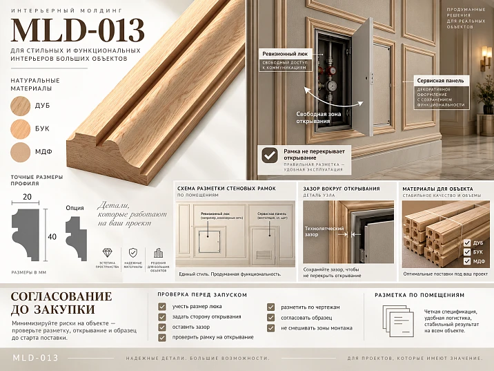
On a large project, the wall layout almost never remains completely standard. In the visualization, the corridor consists of identical frames, but in the actual wall there appear inspection hatches, service doors, removable panels, access to engineering units, and several different sizes of service zones. If you simply multiply one standard frame by the number of rooms, the procurement specification for MLD-013 will be incorrect: some verticals and horizontals will have to be interrupted, shortened, or converted into separate wall types.
Therefore, the correct way to buy MLD-013 moulding wholesale is only after all service zones have been marked on the current elevation drawings and each wall has been assigned a specific type. The working sequence:
wall elevation → service zone → actual opening boundary → wall type → MLD-013 finishing details → 2400/2600 mm material → cutting plan → number of whole strips → marking → reserve → wholesale order.
Main principle:
THE SERVICE ZONE MUST BE APPROVED BEFORE CUTTING THE MOULDING. THE DECOR MUST NOT ACCIDENTALLY CONNECT A FIXED WALL TO AN OPENABLE PANEL OR BLOCK ACCESS TO AN ENGINEERING UNIT.
MLD-013 40×20 mm: what exactly is being purchased
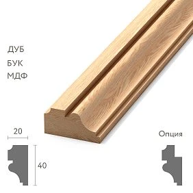
The current STAVROS product page confirms for MLD-013 a single cross-section of 40×20 mm and three main product versions.
| Material | Section | Product length | Sanding | Separate cutting plan |
|---|---|---|---|---|
| MDF | 40×20 mm | 2600 мм | «Prestige» | Yes |
| Beech | 40×20 mm | 2400 мм | «Prestige» | Yes |
| Oak | 40×20 mm | 2400 мм | «Prestige» | Yes |
For MDF, the product page specifies preparation “for enamel.” At the time this article was prepared, the product is offered as a standard profile for interior and furniture finishing; if custom production is required, the current lead time and availability should be rechecked on the product page.
The profile itself can be checked via the link buy molding MLD‑013 40×20 mm.




Why the 40×20 mm cross-section matters for the service zone
This is not a thin line on a drawing. The profile occupies real wall area and creates volume. If the frame runs close to the edge of an access door, its outer contour must be shown to scale. Otherwise, the purchaser may calculate the length along the centerline, and the installer will discover a physical intersection already on site.
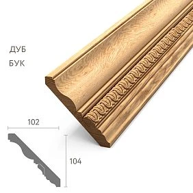
Our factory also produces:


Why 2600 and 2400 mm are counted separately
Finished parts of the same wall are laid out differently across the source planks. The combination 1850 + 650 = 2500 mm potentially fits into MDF 2600, but does not fit into solid wood 2400. Therefore, when switching from MDF to beech or oak, a new cutting plan is needed, not a material substitution in a ready-made estimate.
Get Consultation
Why a general article about wall moldings does not solve this task
General material Wooden wall moldings helps choose a profile and understand the general logic of frames. Here the task is different: the serial frame has already been designed, but service zones turn part of the walls into exceptions that need to be converted into separate kit types.
First engineering and service zones, then decorative frames
A weak workflow looks like this:
drew a perfect frame → a hatch appeared on top of it → on site they started cutting the moulding to fit.
Correct order:
actual service zone → opening or removal boundary → architectural layout → finishing details MLD‑013.
Service zone dimensions cannot be invented in an article. They are obtained:
- from the working design;
- from the specification sheet of the specific hatch or service panel;
- from as-built dimensions;
- from the MEP contractor;
- from the approved service access detail.
Why this is a procurement task, not an engineering task
The article does not determine which hatch is needed or what access the MEP system requires. It helps the buyer avoid ordering a decorative layout before the boundary of that system is confirmed.
What the procurement specialist should receive
For each problem wall, at minimum:
- service zone code;
- its actual dimensions;
- the opening side and trajectory, or the method for removing the panel;
- the boundary within which the decorative profile cannot be considered standard;
- node status — approved / to check / changed.
Why this work cannot be replaced by a general stock
Even a large stock of MLD‑013 does not fix incorrectly calculated geometry. If a horizontal run must be interrupted at a hatch, but it was purchased as a single piece, the extra meters do not turn it into the correct set without new cutting.
It is necessary to account not only for the visible hatch cover, but also for its actual operating zone
A rectangle is visible on the wall facade. But the operational assembly may be more complex. The service zone has:
- visible outline;
- actual leaf;
- perimeter gap;
- opening trajectory;
- removable panel;
- handle, suction cup, push mechanism, or another access method;
- zone required for servicing.
The buyer does not need to assign a universal technological clearance. They need to obtain an already approved boundary within which MLD-013 cannot be routed without a separate decision.
Why the visible outline may be smaller than the functional zone
A removable panel sometimes needs to be pulled out, tilted, or lifted first. A decorative profile that does not cover the lid itself can still obstruct its movement.
Why an opening door and a removable panel are different scenarios
A door has a trajectory on hinges. A removable panel has its own method of extraction. The same outer rectangle does not mean the same permissible molding layout.
What should be considered a sign of an unresolved node
If the drawing shows only the cover, but there is no understanding of how it opens or is removed, the decorative set cannot be considered finally approved.
Four types of wall situations allow standard and exceptions not to be mixed up
For a large object, it is convenient to introduce four basic types.
С-01 — standard wall
There are no service elements. The decorative layout is repeated without changes. It is this type that becomes the main reference module.
С-02 — the hatch is located inside the decorative field
The hatch boundary does not cross the MLD‑013 lines. The frame can remain standard if opening and maintenance do not conflict with the profile. С‑02 should still be checked and recorded separately, because an operational element appears inside the field.
S-03 — the service zone falls on the frame line
A single vertical or horizontal line crosses the opening boundary. A separate drawing is required. The line may be broken, shortened, or the frame may receive new geometry. S-03 can no longer be considered a standard S-01.
S-04 — multiple service zones or a complex non-standard wall
There may be two hatches, a removable panel plus a door, a close portal, or another combination. Such a section does not need to be forced into a standard module. It receives a separate parts list.
| Wall type | Service situation | Can a standard frame be used automatically? | A separate list is required |
|---|---|---|---|
| S-01 | No service elements | Yes, after the reference sample is approved | Standard |
| S-02 | Hatch inside the field | After access verification | It is advisable to secure separately |
| S-03 | Hatch crosses the line | No | Yes |
| S-04 | Multiple service zones | No | Yes |
The presence of a hatch does not always mean a break in the entire decorative frame
The service zone is a constraint, but not a ready-made answer to the design question. Various design solutions are possible:
- the frame lies entirely outside the working zone;
- one side of the frame changes position;
- the standard module is replaced with a special one;
- the hatch receives its own decorative composition;
- part of the molding belongs to the opening panel itself;
- the decorative line is interrupted before the service zone.
Which option is acceptable is decided by the project.
Why you cannot automatically remove the frame around every hatch
This is also an unauthorized change to the architecture. If the hatch is located within a free decorative field and does not interfere with opening, the frame may remain standard.
Why you can't automatically run a profile by the cover
If a piece of MLD‑013 is glued simultaneously to a fixed wall and an opening leaf, it physically connects the two elements. This is an obvious sign that the assembly has not been designed.
A simple control question
Which physical part does each segment of MLD‑013 belong to — the fixed wall or the opening element?
If the answer is “to both,” such an assembly is not yet approved for procurement.
All hatches and service panels must be marked before calculation
On a site with dozens of identical corridors, you can't work with wording like “the hatch by the third door” or “the service panel near the stairs.” Each zone gets a code.
For example:
- L‑01 — small inspection hatch;
- L‑02 — tall service hatch;
- L‑03 — removable panel;
- L-04 — double service zone;
- L-05 — non-standard assembly at the utility cabinet.
| Code | Working area size | Access method | Wall type | Status |
|---|---|---|---|---|
| L-01 | As per project | Opening | S-02 | Approved |
| L-02 | As per project | Opening | S-03 | Check |
| L-03 | As per project | Removal | S-04 | Approved |
Why the hatch code and wall type are different entities
A single L-01 can appear in several wall types if the decorative grid around it differs. And vice versa: C-03 can include different service elements if their effect on the frame is the same.
What is allowed in the final order
Only items with the status "approved". Walls marked "check" remain in the preliminary estimate, but their finish details should not automatically go into mass cutting.
Why this is especially important on a multi-story project
If L-02 changes after the first floor, the code allows you to quickly find all affected walls and update only them, rather than recalculating the entire MLD-013 across the building.
Decorative layouts should be tied to permanent bases, not to a random edge of a hatch
If each module is measured from the nearest hatch, the entire wall system starts to "float". The service element becomes the main geometric reference, even though it may differ in position or size.
It is better to use stable project bases:
- finished floor;
- wall corner;
- the axis of the doorway;
- the approved interior horizontal line;
- the axis of the room;
- another stable architectural element.
How it works on C-01
The standard frame is built from common bases and repeats on all typical walls.
How it works on C-03
First, the overall axis system is preserved, then the service zone cuts or modifies only the area that actually conflicts.
Why this reduces visual chaos
Two adjacent walls with different hatches still retain a common top line, a common rhythm of verticals, and identical base margins. The exception remains local.
One standard module C-01 must have its own parts list
Once a typical wall is approved, it cannot be stored only as an image.
A real parts list is needed, for example:
| Detail | Purpose | Finished length | Quantity on C-01 |
|---|---|---|---|
| V-01 | Left vertical | According to the drawing | 1 |
| V‑02 | Right vertical | According to the drawing | 1 |
| G-01 | Top horizontal | According to the drawing | 1 |
| G-02 | Bottom horizontal | According to the drawing | 1 |
If the composition is more complex, there may be more parts. The key point is that once approved, S‑01 exists as a set of specific elements, not as “approximately 8.4 meters of molding.”
Why parts need to be coded
The code V‑01 or G‑02 makes it possible to manage cutting, packaging, installation, and reordering. Without a code, a short 620 mm segment cannot be unambiguously tied to the correct wall.
How to replicate a standard wall
If S‑01 occurs 28 times:
S‑01 × 28.
Each part is multiplied by 28, after which all parts of the same material are combined into a single cutting list.
Wall S-03 with a hatch must have a different schedule
If a service zone intersects the standard frame, S‑03 is no longer equal to S‑01.
Changes may be as follows:
- left vertical is shorter;
- the vertical is split into two parts;
- the upper horizontal remains standard;
- the lower horizontal is divided into two segments;
- an additional short filler appears;
- one side of the frame is completely absent.
Example of structure С-03
| Detail | С‑01 | С‑03 | Comment |
|---|---|---|---|
| V-01 | 1 | 1 | No changes |
| V‑02 | 1 long | 2 short | Hatch crosses the line |
| G-01 | 1 | 1 | No changes |
| G-02 | 1 | 2 | Break around the service zone |
| D‑01 | 0 | 1 | Special short element |
Why the total wall perimeter may barely change
The sum of decorative lines C-01 and C-03 may differ by just a few centimeters. But the production structure changes significantly: one long part turns into two short ones, additional marking appears, and the cutting layout is different.
Why this matters more than the footage itself
A long vertical of 2200 mm requires almost an entire 2400/2600 strip. Two short parts can efficiently use offcuts. That is why different wall types with similar net footage yield a different number of source strips.
The average consumption per wall cannot be multiplied across the entire project
Bad formula:
8.4 m MLD‑013 × 40 walls = 336 m.
It eliminates the differences between С‑01, С‑02, С‑03, and С‑04.
Correct logic:
С‑01 × 28 + С‑02 × 7 + С‑03 × 3 + С‑04 × 2 → general parts list → cutting.
Why this is especially important for service areas
С‑03 and С‑04 usually contain more short parts. They can improve the overall cutting by using offcuts, but at the same time they increase the number of elements and the risk of mixing up.
What can still be averaged
After the entire order has been calculated by parts, you can derive the average consumption per number, floor, or wall for financial analysis. But this figure should not become the primary purchasing method.
All wall types must be combined into a single master parts list
After calculating С‑01…С‑04, identical parts are aggregated.
For example:
- V‑01 long — 40 pcs.;
- V‑02 standard — 35 pcs.;
- V‑02K short — 6 pcs.;
- G‑01 — 40 pcs.;
- G‑02 standard — 35 pcs.;
- G‑02L/G‑02R — 5 pcs. each;
- special extension pieces D‑01 — 7 pcs.
Why the master list is a bridge to cutting
While there is only “28 walls S‑01 and 3 walls S‑03,” the manufacturer does not see all finished lengths. After merging the parts, it is already possible to optimize the source strips.
Why the origin of the part is still preserved
After cutting, G-02L must know that it belongs to S-03 and to a specific wall. General cutting does not mean depersonalizing the finished parts.
MDF 2600 and beech/oak 2400 mm are recalculated
Suppose the master list contains:
- verticals 1850 mm;
- horizontals 650 mm;
- short parts 420 mm;
- fillers 300 mm.
MDF 2600 mm
Combination:
1850 + 650 = 2500 mm.
Potentially fits in one 2600 mm strip before accounting for the cut.
Array 2400 mm
The same combination:
1850 + 650 = 2500 mm.
Does not fit. Need to look for another pair, for example:
1850 + 420 = 2270 mm.
This is a different cutting plan.
Why you can't recalculate the linear meters using the 2600/2400 coefficient
Parts are not a liquid material. They have specific lengths that either fit into the bar or they don't. Therefore, changing the source length requires a new combinatorial calculation.
Long parts should be laid out first, and short elements around the hatches should be used to optimize the remainder
After separating the materials, the cutting plan is built on the principle of length criticality.
Priority:
- the longest continuous verticals;
- long horizontals of standard walls;
- long parts of special walls;
- medium sides of frames;
- short parts around hatches;
- extensions;
- repair reserve.
Why short C-03 can improve cutting
Suppose that after a 1850 mm vertical from 2600 mm MDF, 750 mm remains. C-03 has a short 620 mm horizontal. If the material and finish match, the remainder can cover this part.
This is a real saving, but it arises after the architecture is approved. You cannot deliberately reduce or shift the frame just for a prettier cutting layout without approval.
Why a long reserve must not be given to short parts
If 2350 mm verticals from 2400 mm oak remain ahead, each requires almost a whole original strip. Even dozens of short C-03 parts must not take these whole pieces while the long requirement is not covered.
What remainder is considered useful
Usefulness is determined by future details. A 680 mm offcut is valuable if C-03 contains elements of 620–650 mm. The same remainder is useless for a 1800 mm vertical. That is why the warehouse stores not only the total footage but also length ranges.
The MLD-013 reserve must be structured, not “plus 10%”
The same percentage across the entire order does not guarantee the required repair configuration.
It is useful to divide the reserve into three types.
Long reserve
Several whole strips of 2400 or 2600 mm for replacing long verticals and horizontals.
Standard module reserve
For example, one complete set of C-01. Such a reserve is especially convenient on a site with dozens of identical corridor sections.
Special reserve
For a recurring C-03 with a specific hatch, you can keep a set of short parts or material sufficient for its restoration.
| Reserve | What is stored | What it covers | Why a separate |
|---|---|---|---|
| Long | Whole planks | Verticals/long sides | Short leftovers do not replace them |
| Standard C-01 | Set of parts or raw material | A regular wall | Quick repair of a standard module |
| Special C-03 | Short and long parts according to the list | Zone with hatch | Unique geometry |
Why a total 20 m of reserve can be worse than two whole planks
If the 20 m consists of offcuts of 300–700 mm, a long vertical cannot be restored. Two whole oak planks of 2400 mm have a smaller total linear meterage but higher repair value for long elements.
Floor-by-floor delivery must be packaged by wall types, not just by meters
Phrase:
“floor 3 — 95 m MLD‑013”
does not answer whether all walls are closed.
Strong output:
- С‑01 — 8 sets;
- С‑02 — 2 sets;
- S-03 — 1 set;
- special parts L-02 — 1 set;
- long reserve — separately.
Why completeness matters more than total meterage
The warehouse may have 100 m of profile, but one short G-02L for S-03 may be missing. Formally, there is plenty of material, but in fact the specific wall is not ready.
Floor-by-floor schedule
| Floor | С‑01 | S-02 | С‑03 | S-04 | Status |
|---|---|---|---|---|---|
| 2 | 8 | 2 | 1 | 0 | Ready |
| 3 | 8 | 1 | 1 | 1 | Ready after S-04 |
| 4 | 7 | 2 | 0 | 1 | Check S-04 |
Why a problematic S-04 cannot be covered by general stock
Until the geometry is approved, the actual lengths are unknown. You can keep a preliminary reserve of raw materials, but you cannot label it as a finished S-04 kit.
Changing the hatch size after ordering requires a new revision only of the affected wall type
If L-02 has become taller or wider, there is no need to recalculate the entire project. First, determine which wall types use this hatch.
For example:
S-03.R1 — the original version.
After the change:
S-03.R2 — new service area size.
What to recount
- which verticals have changed;
- which horizontals have become shorter/longer;
- whether new short parts have appeared;
- whether already purchased planks can be used;
- can the P1 parts be redistributed to other zones;
- what additional order is needed.
Why the total footage may barely change
The hatch shifted by 100 mm: the left horizontal became shorter, the right one longer. The sum may remain the same, but the two finished P1 parts no longer fit. Therefore, checking only by meters will not detect the problem.
How to preserve history
| Type | Version | Where it applies | Status |
|---|---|---|---|
| S-03 | R1 | floors 2–3 | Installed |
| S-03 | R2 | Floors 4–5 | Active |
The old version is not deleted because it is needed for operation and explains why the parts differ across floors.
If a service hatch appeared only on the construction site, you cannot simply cut out a piece of an already installed frame
The late appearance of a service zone is a real scenario. But the correct order does not change:
stop a specific section → take as-built dimensions → update the layout drawing → determine the new wall type → get the parts → check the remnants → release a new version → only then install.
Why "we'll cut it later" creates secondary problems
Random trimming can:
- leave an asymmetrical end;
- cross the door's path;
- create a short visible stub;
- break the rhythm of the neighboring frames;
- deprive the wall of maintainability.
What can be used from what has already been purchased
Free remnants of the same material and finish. But only after the new C-version has provided exact lengths. The remnant is selected to fit the part, not the part invented to fit the remnant.
Why the article does not assess the acceptability of the hatch itself
This is a matter for the design and engineering section. Only the impact of the already approved service zone on the MLD-013 decorative specification is considered here.
Packaging, receiving, and warehousing must preserve the wall type, not just the MLD-013 item code
After the parts are calculated, the moment comes when a good specification is easily lost: production or the supplier ships the planks, the warehouse sees a single MLD-013, while the site needs different sets C-01, C-03, and C-04.
Therefore, a wholesale batch has two levels of accounting:
product level — MLD-013 / material / 2400 or 2600 / finish;
site level — floor / wall type / hatch code / parts set / reserve.
The packaging frame helps to preliminarily estimate logistics
The current MLD-013 card specifies a rigid packaging frame costing 390 ₽, and one frame holds up to 10 MDF items or up to 5 solid wood items. This can be used for preliminary planning of space and the number of packaging units, but the actual breakdown of a large batch must be confirmed when placing the order.
For example, 87 MDF planks:
87 / 10 = 8,7.
With full filling, mathematically at least 9 frames are required.
For 37 oak planks:
37 / 5 = 7,4.
The minimum is 8 frames under the current limit of “up to 5.” But if the batch is deliberately split by floors and wall types, there may be more packaging units.
Why you shouldn’t build an article around the price of packaging
Packaging is a service part of the order. The main risk of this article is not the extra 390 ₽, but that short parts S‑03 or planks of different materials end up in the wrong set. Therefore, packaging matters only as a means of preserving the structure of the specification.
How to label factory or on-site packaging
Example of a commercial pack:
MLD‑013 / MDF / 40×20×2600 / O‑01 / floor 3.
If pre-cutting has been performed:
E3 / S‑03.R2 / L‑02 / set 1 of 3.
If the interior contains whole planks intended for several wall types at once, it is better not to write a single C-code as if they were already fixed. In that case, indicate “free cutting floor 3” or another internal status.
Why short special parts need to be packed especially carefully
Two segments may differ by only 20–40 mm and look almost identical. One belongs to the left side of hatch L‑02, the other to the right side of L‑03. Without labeling, the installer can easily swap them and discover the error only at the end of the frame.
Acceptance of whole planks
Checked:
- item code MLD‑013;
- the material;
- cross-section 40×20 mm;
- commercial length 2600 or 2400 mm;
- quality/finish according to the order;
- quantity for each line;
- obvious transport damage;
- batch marking.
Acceptance of the pre-cut batch
Added:
- wall code;
- part code;
- finished length;
- left/right side, if applicable;
- C-type version;
- floor/room.
Why the total can match despite an actual mix-up
Order:
- 80 MDF planks;
- 20 oak;
- 10 beech.
Total 110.
Actual:
- 75 MDF;
- 25 oak;
- 10 beech.
The total is 110. But MDF is short by five strips, and oak arrived five extra. On a project with long parts of 2500 mm, this is especially critical: an extra oak 2400 does not replace the missing MDF 2600.
How to issue material per floor
Not:
"MLD-013 — 72 m."
But:
floor 3: C-01 × 8, C-02 × 2, C-03.R2 × 1, free reserve MDF 2600 × 2 strips.
This way the warehouse sees not only the volume, but also the installation readiness.
Return of leftovers after installation
The leftover is returned with length and product identity:
MLD-013 / MDF / O-01 / 1280 mm × 2.
Bad:
"molding remainder — 2.56 m".
The second entry loses the length structure, and it is precisely this that determines whether the future part can be closed.
How to build a remainder bank
| Execution | Whole | 1800+ | 800–1799 | 300–799 |
|---|---|---|---|---|
| MLD‑013 / MDF / O‑01 | ___ | ___ | ___ | ___ |
| MLD‑013 / oak / T‑01 | ___ | ___ | ___ | ___ |
| MLD‑013 / beech / E‑02 | ___ | ___ | ___ | ___ |
How to prepare a supplier request
Working wording:
"We kindly ask you to calculate a wholesale batch of MLD‑013 molding 40×20 mm for the wall decorative frames of the project. Material — according to the specification. The walls are divided into standard and special types; the areas of access hatches and service panels are accounted for in the approved elevations. The quantity of commercial strips is calculated according to the finished parts list and the cutting map. The reserve is allocated separately. Please confirm the current price, availability or production time, packaging, and delivery".
Such a request immediately shows that the order is built on real parts, not on rough linear meterage.
Full example: hotel, 40 walls and four configuration types
Let's consider a hypothetical object to demonstrate the calculation mechanics without presenting made-up dimensions as a real project.
Across five floors — 40 wall sections:
- S-01 — 28 walls;
- S-02 — 7 walls;
- S-03 — 3 walls;
- S-04 — 2 walls.
After approving the elevations, we obtained the following hypothetical finished sets.
S-01:
- 2 verticals of 1850 mm each;
- 2 horizontals of 680 mm each.
Net length:
2×1.85 + 2×0.68 = 5.06 m.
C‑02:
The hatch is located inside the field and does not cross the profile, so the geometry of MLD‑013 matches C‑01:
5.06 m.
C‑03:
- 1 vertical 1850 mm;
- 2 short verticals of 620 mm each;
- 1 top horizontal 680 mm;
- 2 bottom sections of 290 mm each;
- 1 short filler 420 mm.
Net length:
1.85 + 2×0.62 + 0.68 + 2×0.29 + 0.42 = 4.77 m.
S-04:
Suppose two service zones create more short parts, but the total net consumption of one wall is 4.55 m.
Total net linear meters of the project:
28×5,06 + 7×5,06 + 3×4,77 + 2×4,55.
Let's calculate:
141.68 + 35.42 + 14.31 + 9.10 = 200.51 m.
If we simply take the average consumption:
200.51 / 40 ≈ 5.01 m per wall.
And multiply 5.01 by 40, the net linear meters will be correct. But such an average figure says nothing about the actual number of planks, because S-03 and S-04 contain far more short elements, while S-01 requires long verticals.
How the same example looks in MDF 2600 mm
First we take the long verticals of 1850 mm.
For C-01 and C-02, their:
(28 + 7) × 2 = 70 pcs.
For C-03 — 3 more long verticals.
Total:
73 verticals of 1850 mm each.
From a 2600 MDF board, after one vertical, approximately the following remains:
2600 − 1850 = 750 mm.
This is a very useful offcut, because the standard horizontals for C-01/C-02 in our example are 680 mm. So a strong combination is:
1850 + 680 = 2530 mm.
About 70 mm remains before accounting for the cut.
If the combination works technologically, 70 of the 73 long verticals can be combined with 70 horizontals of 680 mm. The remaining short parts C-03/C-04 are then laid out on the free strips and offcuts.
This shows why service zones do not necessarily increase consumption: short parts sometimes conveniently absorb the leftovers. But such savings appear only after the geometry of C-03 has already been approved.
How the same set changes in oak 2400 mm
For oak:
2400 − 1850 = 550 mm.
The standard horizontal 680 mm no longer fits next to the vertical.
But the short vertical C-03 620 mm also does not fit:
1850 + 620 = 2470 mm.
However, the filler 420 mm:
1850 + 420 = 2270 mm.
can become a useful pair.
The commercial length decreased by only 200 mm, but the structure of the optimal cutting layout changed completely. Therefore, you cannot take the number of MDF strips and multiply it by a coefficient for oak.
Systematic length error on three walls of C-03
Suppose that during the first calculation, the lower right part of L‑02 was mistakenly taken as 310 mm instead of 290 mm. The error is 20 mm per wall.
For three S‑03:
20 × 3 = 60 mm.
From the point of view of total meterage, 60 mm is negligible. But if all three parts have already been cut at 310 mm, they can potentially be shortened to 290 mm and saved.
If the error is the opposite — they were cut at 270 mm instead of 290 — the total shortfall is also only 60 mm, but all three parts need to be remade. That is exactly why a part error and a total meterage error are different things.
Changing the hatch after the first phase: how not to recalculate the entire building
Suppose floors 2–3 have already been installed according to S‑03.R1. Before floor 4, the engineering contractor changes L‑02: the service zone becomes 80 mm wider.
New version:
S‑03.R2.
Only the set of parts associated with L‑02 is checked. For example:
- the upper horizontal remains unchanged;
- the left short vertical remains;
- the right short vertical changes;
- the two lower horizontals receive new lengths;
- the D‑01 filler disappears.
Instead of recalculating the entire article across 40 walls, the object changes only three or four rows of the C‑03 list.
Next, the R1 remnants are checked:
- if the old right segment is longer than the new one, it can be shortened;
- if it is shorter, a new one is needed;
- if the old G‑02L fits another wall type, it can be redistributed;
- if it does not fit, it remains as R1 reserve or as waste at the production department's discretion.
Reverse check 200.51 m: from the total back to the actual walls
After all calculations, accounting or the procurement specialist sees a clean total of 200.51 m. A good system allows it to be broken down:
- 141.68 m → 28 С‑01;
- 35.42 m → 7 С‑02;
- 14.31 m → 3 С‑03;
- 9.10 m → 2 С‑04.
And each С‑type is further broken down into specific В‑ and Г‑parts.
If part of the total meterage cannot be traced back to a wall type, an “undescribed reserve” or double counting has appeared in the specification. If a wall type exists but is not broken down into specific parts, it is not yet ready for production.
How the first installation batch checks the quality of the entire model
It is useful to start not with forty walls, but with the first five to eight sets. After installation, the following are compared:
- estimated number of parts;
- actual consumption;
- return of usable leftovers;
- ease of marking;
- actual operation of the hatch after frame installation;
- repeatability of С‑01;
- correctness of С‑03.
If every С‑03 requires manual trimming beyond the drawing, the wall type is not described precisely enough. It is better to correct the R-version after three walls than after thirty.
How to assess actual consumption without false overconsumption
The warehouse may issue two whole planks more than the estimated requirement for С‑01 so that the crew does not wait for replenishment. This does not mean that two planks are “consumed.” After installation, it is necessary to separate:
- ISSUED;
- installed;
- returned whole;
- returned as useful remnants;
- written off as damage/waste.
Only the actual balance is used for the next queue.
When short parts C-03 are more profitable to produce in separate batches
If one type of hatch is repeated dozens of times, its short parts can be grouped:
G-02L × 20, G-02R × 20, V-02K × 40.
This is more convenient than cutting each set separately. Production sets the length once, marks the batch, and issues it by floors.
But if L-02 has two versions R1/R2, they should not be mixed into one batch just because of similar dimensions.
Why service panels sometimes reduce the purchase volume but should not be designed for the sake of savings
Splitting a long vertical into two short parts can make it possible to use remnants that were previously useless. C-03 is sometimes indeed cut more efficiently than C-01.
But first, there is the engineering and architectural assembly. You cannot change the hatch position, frame size, or molding line just so it "fits better into 2400." Optimization begins after the design is approved.
Decision tree: treat the wall as standard or convert it to a special type
Step 1. Is there a service zone on the wall?
No → the wall can remain S‑01 if the other parameters match the reference.
Yes → we move on.
Step 2. Does the working zone of opening or removal cross the outer contour of MLD‑013?
No → the wall can be S‑02: the decorative geometry is potentially standard, but the assembly needs to be checked physically.
Yes → this is at least S‑03.
Step 3. Are there multiple service zones, or is there a door, column, or panel nearby?
Yes → it is better to designate S‑04 or another special type rather than try to describe the wall as "S‑03 plus one more adjustment."
Step 4. Are all finished parts known?
No → the wall remains in the "check" status and is not included in the final cutting list.
Yes → the wall can be included in the master schedule.
This algorithm allows separating truly standard walls from those where a service unit affects the decor. It does not determine engineering...
Therefore, separating C-types before ordering is not a formality. This is the cheapest point to eliminate a systemic error.
18 mistakes, a checklist, and situations when a mass order must be stopped
1. Multiply one standard wall across the entire floor
Why it happens: in the visualization, the corridors look identical. Consequence: walls with hatches receive incorrect parts. How to prevent: C-01/C-02/C-03/C-04 before calculation.
2. Count only the visible hatch cover
Reason: it is the easiest to measure. Consequence: MLD-013 does not intersect the cover, but it interferes with opening or removal. Prevention: use the approved access work zone.
3. Measure the frame from a random edge of the hatch
Reason: it is easier on site. Consequence: the rhythm of the frames "drifts" from wall to wall. Prevention: fixed architectural datums.
4. Glue one molding simultaneously to the wall and to the opening door
Reason: one wants to preserve a continuous line. Consequence: the profile physically connects two elements. Prevention: each segment must belong to a single physical part.
5. Automatically break the frame at any hatch
Reason: a service element is perceived as an absolute prohibition. Consequence: the architecture changes unnecessarily. Prevention: first check the actual working zone.
6. Apply an average consumption per wall
Reason: convenient for the estimate. Consequence: short and long parts of different types get mixed. Prevention: a master parts schedule.
7. Treat C-03 as the same as C-01 with a "minor adjustment"
Reason: the total linear meterage is almost the same. Consequence: the length structure and the number of elements do not match reality. Prevention: a separate code and schedule.
8. Calculate MDF, then replace it with oak without a new cutting plan
Cause: the profile and cross-section are identical. Consequence: 2600 mm combinations no longer fit into 2400. Prevention: a new cutting plan for each material.
9. Cut short C-03 before long C-01
Cause: short parts are easier to produce. Consequence: solid strips are consumed, and long verticals do not have enough length. Prevention: prioritize length.
10. Add 10% and do not count the parts
Cause: the usual reserve. Consequence: there is reserve in meters, but no specific long or special part. Prevention: reserve after cutting.
11. Do not account for the material of the control assembly
Cause: the sample is perceived as part of the general installation. Consequence: several strips disappear from the production batch. Prevention: a separate “reference” line.
12. Do not label short special parts
Cause: they are similar in length. Consequence: the left part of L-02 goes to L-03. Prevention: floor / wall type / hatch code / part code.
13. Accept delivery only by the total number of slats
Reason: all goods are called MLD-013. Consequence: mixing of MDF/solid wood was not detected. Prevention: line-by-line acceptance.
14. Count stock only in meters
Reason: warehouse accounting is simpler. Consequence: 12 m of short offcuts are mistakenly counted as stock for a long vertical. Prevention: length ranges.
15. Do not issue a new revision after changing the hatch
Reason: the overall external wall pattern appears the same. Consequence: production cuts to the old dimensions. Prevention: S-03.R1/R2 with the transition date.
16. Cut the hatch in an already installed frame without a new drawing
Reason: the service zone appeared late. Consequence: random endings and disrupted rhythm. Prevention: stop the assembly and issue a new wall type.
17. Use leftover stock of another finish
Reason: the length and material are suitable. Consequence: visible color mismatch or a different surface. Prevention: leftover stock inherits the full product configuration.
18. Order the entire MLD-013 up to current layouts
Reason: they want to lock in the price or speed up the project. Consequence: a significant portion of the material ends up not tied to actual details. Prevention: before the final order, finalize the wall typology and service zone assemblies.
Checklist before payment
| Check | Status |
|---|---|
| MLD-013 confirmed | ___ |
| 40×20 mm confirmed | ___ |
| MDF 2600 and solid wood 2400 separated | ___ |
| All service zones marked | ___ |
| Each hatch has an L-code | ___ |
| Opening/removal method known | ___ |
| С-01/С-02/С-03/С-04 defined | ___ |
| "Check" statuses closed | ___ |
| Permanent marking bases set | ___ |
| Part lists issued | ___ |
| Finish lengths confirmed | ___ |
| MDF cutting plan built | ___ |
| Beech/oak cutting plan built separately | ___ |
| Long parts reserved first | ___ |
| Control unit accounted for | ___ |
| Reserve structured | ___ |
| Floor-by-floor kit complete | ___ |
| Marking approved | ___ |
| C-type versions up to date | ___ |
| Return of leftovers takes lengths into account | ___ |
| Reorder format approved | ___ |
It is still too early to buy MLD-013 in bulk
A bulk order is premature if:
- hatches exist only in the engineering plan and are not coordinated with the interior;
- the actual opening area is unknown;
- wall elevations are outdated;
- S-01 and S-03 are considered the same type;
- the material may change;
- 2400 and 2600 are calculated the same way;
- only the total linear footage is available;
- the reserve is set as a single percentage;
- it is unclear which physical part the molding near the hatch refers to.
At this stage, you can request a price and reserve a budget. But turning a preliminary linear footage into a final order is risky.
When MLD-013 itself may not be the best solution
If 40×20 mm is too large for narrow fields near service panels, the profile forces too much change to the frame or creates inconvenient terminations, it is worth comparing a more compact molding. Unifying the SKU should not worsen serviceability or architecture.
Final algorithm, useful links, and wholesale order questions
Final algorithm
CONFIRM MLD‑013 → LOCK 40×20 MM → SEPARATE MDF 2600 AND SOLID WOOD 2400 → ASSEMBLE CURRENT LAYOUTS → APPLY ALL SERVICE ZONES → ASSIGN L-CODES → OBTAIN OPENING/REMOVAL BOUNDARIES → DIVIDE WALLS INTO С-01/С-02/С-03/С-04 → ANCHOR FRAMES TO PERMANENT BASES → ISSUE FINISHED PART SCHEDULES → MERGE IDENTICAL PARTS → BUILD CUTTING PLANS FOR 2600 AND 2400 SEPARATELY → RESERVE LONG ELEMENTS → USE OFFcuts FOR SHORT С-03 → COUNT WHOLE STRIPS → ADD STRUCTURED RESERVE → DISTRIBUTE BY FLOOR → MARK → ACCEPT DELIVERY LINE BY LINE → ACCOUNT FOR RETURNS → WHEN THE HATCH IS REVISED, ISSUE A NEW С-VERSION → REORDER BY FULL LINE.
Product links
For a specific product, use wooden molding MLD‑013.
If the profile has not yet been selected and a general selection of wall decor is needed, this material is useful Buy Wall Molding.
For a large purchase of several types of moulding, you can use linear products wholesale.
General B2B requests in a large order
If the project is purchased through construction materials suppliers moscow, building materials supplier companies, large building material suppliers, company building materials, wholesale building materials, building materials wholesale from the manufacturer, construction and repair goods wholesale or building materials wholesale, technical specification MLD‑013 must still preserve C‑types and materials.
The same rule applies to construction material databases, building materials wholesale in Moscow, building materials from the manufacturer, building materials wholesale Moscow, building materials distributor, wholesale purchases of building materials, construction materials wholesale и construction material deliveries. A general contract does not turn C‑01 and C‑03 into the same set.
What size is MLD-013?
The cross-section is 40×20 mm. MDF is supplied in lengths of 2600 mm, beech and oak — 2400 mm.
Can MLD-013 be purchased wholesale for wall frames?
Yes. But the final quantity is best calculated after separating standard and special walls and building a cutting map.
Should a wall with an inspection hatch be counted as a separate type?
If the hatch affects the decorative lines, yes. If it is entirely within the free field and does not obstruct access, the geometry may match the standard one, but the check should still be recorded.
Can MLD-013 be routed through an opening service door?
Only if the approved detail explicitly provides for such a scenario and the molding belongs to a single physical part. One segment must not be accidentally glued simultaneously to the fixed wall and the leaf.
Why can't you simply multiply the linear meters of one wall?
Because S-03 and S-04 yield a different set of parts. The total linear meters may be similar, but the number of long/short elements may differ.
Can short parts around the hatch be made from offcuts?
Yes, if the material, finish, and required length match. Critical long elements are reserved first, then offcuts are allocated to short ones.
What reserve should be kept?
Separately, whole long planks, the standard S-01 set, and, if necessary, a reserve for the recurring special type S-03. There is no universal percentage.
Should the order be recalculated when switching from MDF to oak?
Yes. The original length changes from 2600 to 2400 mm, so the cutting combinations and the number of full strips change.
How to label parts of different walls?
For example: E3 / S-03.R2 / L-02 / G-02P. Such a code shows the floor, wall type, specific hatch, and part.
What to do if the hatch changed after ordering?
Release a new version of the affected S-type, recalculate only the changed parts, check free remnants, and then place the additional order.
What to do if the hatch appeared already on the construction site?
Do not cut out a random section of the finished frame. First take measurements, update the layout, and determine the new wall assembly version.
How to place an additional order?
Not "another 6 meters of molding," but: MLD-013 / MDF / 40×20×2600 / S-03.R2 / floor 4 / number of full strips or specific parts.
When should the order be stopped?
If the service zones are not yet coordinated with the interior, there are no opening boundaries, no current layouts, or the quantity exists only in total linear meters.
Before final payment, it is useful to perform one last reverse check: every procurement line should be traceable down to specific C-types and walls, and every wall type should be traceable back to a set of parts and the source strips of the required material. If the order lists five additional strips, but it is impossible to explain which reserve, floor, or revision they are intended for, that is not managed stock but an undescribed surplus. If, conversely, the schedule contains a long vertical run, but not a single whole 2400/2600 mm strip is reserved for it, the project is formally accounted for but not physically provisioned.
For recurring service zones, it is worth also keeping a set of operational documentation: the current version of C-03/C-04, codes L-01…L-05, photos of the finished assembly, finished lengths of special parts, and remaining material. Then a repair several years later begins not with dismantling the adjacent frame to take measurements, but with precise identification of the part. Such archival discipline is especially useful in hotels, apart-hotels, and offices, where identical engineering zones repeat dozens of times and one correct schedule allows any typical section to be quickly restored.
It is also worth keeping a separate list of exceptions that were not included in the mass scheme: one-off hatches of non-standard size, late engineering changes, and walls with different finishes. Such items are best kept as standalone lines so that the next revision does not turn an exception into an erroneous “new norm” for the entire floor.
This also simplifies the final reconciliation of ordered, installed, and remaining material before closing the last phase of the project and handing over documentation to operations without re-inventorying all walls manually.
After such preparation, buying molding MLD-013 wholesale means ordering not impersonal hundreds of meters of 40×20 mm profile, but a verifiable set of standard and special wall kits, where every revision hatch is accounted for down to the cut, long parts are protected from accidental consumption, and floor-by-floor delivery and reordering can be restored from a single master specification.