





Article Contents:
- Where to buy wooden moldings in Lipetsk and what to specify in your order
- Which solid wood moldings are suitable for a fine ceiling layout
- MLD-002 22×11 mm: the main profile for twelve fields
- MLD-004 15×8 mm: when you need a calmer rhythm
- Oak or beech: don't choose on price alone
- What a 3×4 ceiling grid means and what it is not
- Measuring a 4700×3130 mm ceiling: real geometry first
- How to position two longitudinal and three transverse moldings
- Cross pieces: why there are nine of them when there are only three lines
- Longitudinal lines: four pieces of 2350 mm each and a central joint
- Bill of materials of thirteen pieces: why the total equals 18.724 m
- Option A: the full set made of 2400 mm moldings
- Option B: seven long moldings and three one-metre moldings
- Checking machining allowances before cutting
- MLD-004: recalculating the central pieces and the new total
- How much oak and beech moldings cost: four estimates
- Six intersections and two joints: what the installer must decide
- Ceiling base: when a decorative grid is even possible
- How to fasten wooden moldings and which mistakes to avoid
- Lighting, ventilation and ceiling pattern lines
- How to align the inner grid with the ceiling cornice
- Finishing and care: how not to ruin the pattern after installation
- When it is better to avoid such a grid
- How to order a set with delivery to Lipetsk
- Frequently asked questions about wooden ceiling moldings
- Can MLD-002 be replaced with MLD-004 without changing the drawing?
- Why are there thirteen parts in the specification instead of twelve?
- Is one 2400 mm strip enough for a 2350 mm long part?
- Why isn't the saving on a mixed order always guaranteed?
- Can solid wood moldings be used on a stretch ceiling?
- Do you have to choose oak if you need a visible texture?
- Can three one-meter moldings be replaced with one long piece, and can the offcuts be used?
- How can I tell that the price in the article is current?
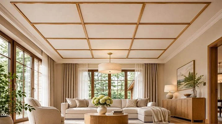
A room ceiling measuring 4700 by 3130 mm can be divided by moldings into twelve rectangular panels. Such a composition requires just two longitudinal lines and three transverse ones. But the phrase “buy twenty meters of molding” is not yet a specification: ready-made strips have a fixed length, and intersecting profiles cannot simply be laid on top of each other. It is the cutting plan and the six intersection nodes that determine whether the order will be sufficient.
For the room in question, a preliminary calculation of MLD-002 gives 18.724 m of finished parts. Buying only 2400 mm strips would require nine pieces, while combining lengths requires seven at 2400 mm and three at 1000 mm. The second option reduces the paid meterage from 21.6 to 19.8 m. The difference is noticeable even in a small room; at the same time, no calculation relieves you of checking how the wooden profile is attached to the ceiling.
This is an example of a decorative overlay grid, not a load-bearing coffered ceiling. The profile cross-section, joint locations and actual installation method are agreed upon according to the drawing and with the contractor before payment. Below is a verifiable bill of materials that is convenient to attach to a supply request to Lipetsk.
Where to buy wooden moldings in Lipetsk and what to specify in the order
For a Lipetsk resident who needs not an abstract "ceiling decor" but a specific solid wood set, it is more convenient to start with the room dimensions and a list of parts. In the STAVROS catalogue you can buy wooden mouldings in Lipetsk with delivery arranged. This is a link to the general mouldings section, which presents mouldings, cornices and other profiles; the required item code should be checked on its own product page.
For the project in this article, MLD-002 or MLD-004 are provided. Both products are available in oak and beech versions, and the offered commercial lengths include 1000 and 2400 mm. Different lengths of the same item code are not interchangeable price positions. The buyer must state not only the total metreage but also how many long and short strips are needed.
In the first enquiry it is useful to state the city, the wood species, the item code, the desired cross-section, the number of pieces of each size and the intended finishing method. If the ceiling grid is planned to be painted, the preparation of the wood for an opaque coating should be discussed separately. If the visible grain is to be preserved, the outer surface of the entire batch must be agreed: on a large ceiling plane, differences in shade are more noticeable than on individual samples in hand.
The presence of an item on the electronic product page should not be taken as a promise that the entire batch is available and will be dispatched to Lipetsk immediately. Stock levels change, and completing an order may require items from a single batch or additional manufacturing. The pack size and the transport conditions for long profiles are also agreed before purchase.


Which solid wood mouldings are suitable for a fine ceiling layout
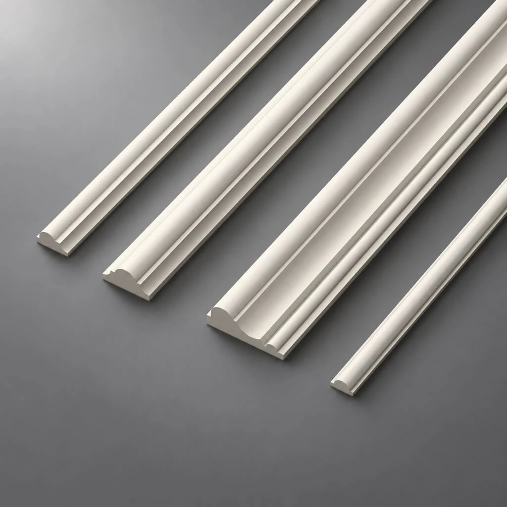
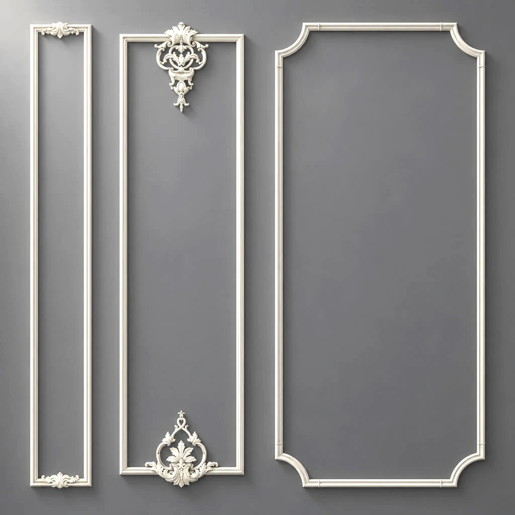
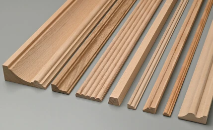
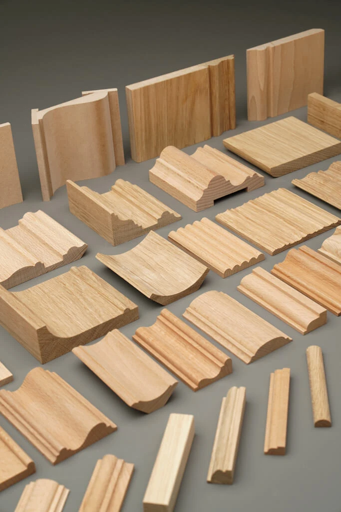
The name "wooden moulding" covers products with different cross-sections. Two similar strips may differ in the width of the bearing surface, the height of the relief and the transition line to the painted base. For a grid, repeatability of shape is important: the intersection of four sections requires exact matching of profiles, and the joint on a longitudinal line must not create a step.
The STAVROS catalogue confirms the following versions in oak and beech. The letter L denotes the commercial length, and dimensions A and C refer to the cross-section. Before transferring the values to the installation drawing, the orientation of the profile should be checked against its working drawing.
| Model | Cross-section A×C | Oak and beech lengths | Possible application |
|---|---|---|---|
| MLD-001 | 10×6 mm | 1000 and 2400 mm | Very fine pattern in a small room |
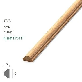
| MLD-002 | 22×11 mm | 1000 and 2400 mm | Main layout grid with pronounced relief |
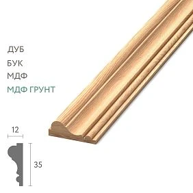
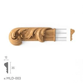
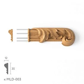
| MLD-003 | 35×12 mm | 1000 and 2400 mm | More defined lines and a visible shadow |
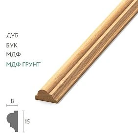
| MLD-004 | 15×8 mm | 1000 and 2400 mm | A finer alternative for a calm ceiling |
| MLD-028 | 25×11 mm | 2400 мм | A different profile expressiveness; separate length calculation |
MLD-001 and MLD-003 are needed in this project mainly to compare the scale of the line. They should not be quietly substituted for the main profile, even if the order length matches: the dimensions of the free margins and the character of the joints will change. MLD-028 has a different range of lengths, so the combined purchasing scheme with one-metre strips does not automatically carry over to it.
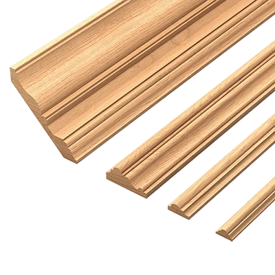
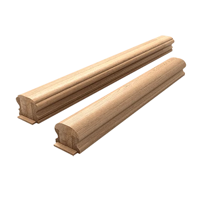
Choosing a profile from a single enlarged photo is inconvenient. The photo shows the relief but does not indicate which face of the moulding sits against the ceiling or how far it protrudes above the base. You should request the current working drawing from the seller and give the installer a printed or digital dimensional section fragment. For a complex composition, it is worth ordering a sample before the main batch.
Our factory also produces:
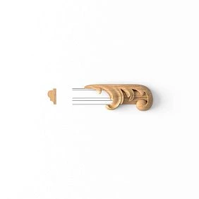
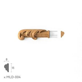
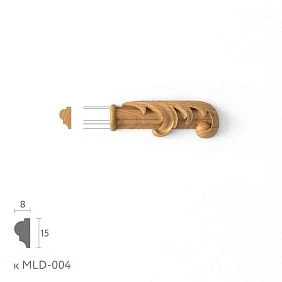
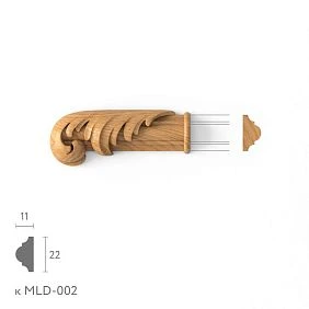
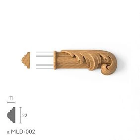
MLD-002 22×11 mm: main profile for twelve fields
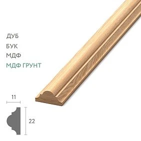
The option under consideration uses wooden moulding MLD-002 made of oak or beech. Its stated cross-section is 22×11 mm. These values cannot be arbitrarily swapped: the height of one measurement does not turn it into the width of the occupied strip. For a preliminary calculation, it is assumed that one longitudinal strip on the ceiling occupies 11 mm; this is finally confirmed by the drawing and the installation orientation.
Why was this particular profile chosen? On a ceiling slightly more than three metres wide, a line about a centimetre wide creates a graphic division but does not turn into a massive beam. The relief itself will cast a slight shadow in side light. This character is suitable when the flat plane between fields needs to be preserved and the ceiling should not be lowered by a frame.
There is also a downside to compactness. At a distance of several metres, a thin profile is perceived primarily as a line of colour and shadow rather than as an elaborate stucco pattern. If the task is to show deep coffers, it is not enough. A different construction or a more developed architectural framing is needed, which is calculated separately.
The project will use four longitudinal pieces of 2350 mm, three central crossbars of 1208 mm and six side crossbars of 950 mm. The profile is supplied in retail strips of 1000 and 2400 mm, so this bill of materials allows two honestly comparable purchases to be made. A length of 2350 mm leaves 50 mm from the original strip for trimming; this may be enough, but the allowance is assessed taking into account defects, ends and the actual kerf width.
Do not buy moulding for the ceiling pattern alone without finding out how the junctions will be made. For the central intersection, the position of the longitudinal joint is especially important: two 2350 mm sections form a seam exactly on the middle transverse axis when the room length is divided equally. This node requires a separate working solution, not a random on-site trim.
Get Consultation
MLD-004 15×8 mm: when a calmer rhythm is needed
An alternative is Wooden Moulding MLD-004. The 15×8 mm cross-section makes it visually thinner than MLD-002. The 3 mm difference in the nominal width of the installed strip seems insignificant until a long crossbar between two longitudinal lines has to be recalculated.
With the same ceiling width of 3130 mm and the same side free margins of 950 mm, the central field will become 1214 mm instead of 1208 mm. That is only six additional millimetres, but the transverse piece cannot be cut according to the old bill of materials: an unnecessary gap will form near the joint. In a project with identical mouldings, such a shortcoming will be repeated three times.
The decorative impression will also change. MLD-004 is more appropriate when the ceiling already has a sufficiently expressive perimeter frame, and the inner grid should only neatly divide the surface. On a very light ceiling, thin lines can be matched to the paint color, creating a play of shadows without the contrast of wood. On a dark base, a similar profile with a light finish becomes a noticeable graphic pattern.
From an economic standpoint, MLD-004 is cheaper at the prices given below, but the final benefit depends not only on the price per piece. You need to make sure that all 13 parts can be cut from the same stock lengths as MLD-002. For the selected grid, this is possible based on nominal dimensions: the four long parts remain at 2350 mm, the three central ones become 1214 mm each, and the six side ones become 950 mm each.
One article should be used across the entire grid. Combining MLD-002 on the longitudinal lines and MLD-004 on the transverse ones can be conceived as a separate design technique, but such a solution is no longer the calculation given here. At the six intersections, it will require special transitions, and working with the joining of different profiles may cost more than the savings on material.
Oak or beech: choosing not only by price
Oak and beech are the two solid wood options presented in the specified cards. In a photo of an individual strip, the shade may seem to be the main difference. On a ceiling, where moldings repeat at equal intervals, the consistency of the wood grain, surface preparation, and finish quality are more noticeable.
Oak is usually chosen when the structure needs to remain visible. With a clear finish, the differences in fibers form a lively, not entirely uniform pattern. It cannot be promised to be absolutely identical on all parts: even within one species, individual strips differ. Beech has a different, more even texture character and often turns out to be a convenient choice for subsequent opaque painting. But it would be incorrect to claim that beech does not change geometry at all when humidity changes. Both materials require a stable indoor climate.
There is a perceptual peculiarity on a ceiling: a person rarely examines wood pores up close. The eye simultaneously takes in dozens of meters of lines and compares their tone. If the goal is a warm natural oak pattern, coordinate the tone before installation. If the surface will be fully painted, you can discuss a beech set and a suitable primer and paint system.
You should ask not only "which species is better to buy," but also "what surface should result after finishing." On a test sample, check the compatibility of the primer, varnish, or enamel with the specific wood, and evaluate the color under daylight and artificial lighting. Do not apply the first test directly to an already installed grid: redoing twelve fields is much harder than rejecting an unsuitable shade on one short part.
For a consistent result, it is desirable that all strips of one visible contour be close in texture and finish. When replacing a damaged element after installation, it may be difficult to reproduce the previous tone. Therefore, a spare strip is useful not only as a reserve for cutting errors, but also as material for future local repairs.
What a 3×4 ceiling grid means and what it is not
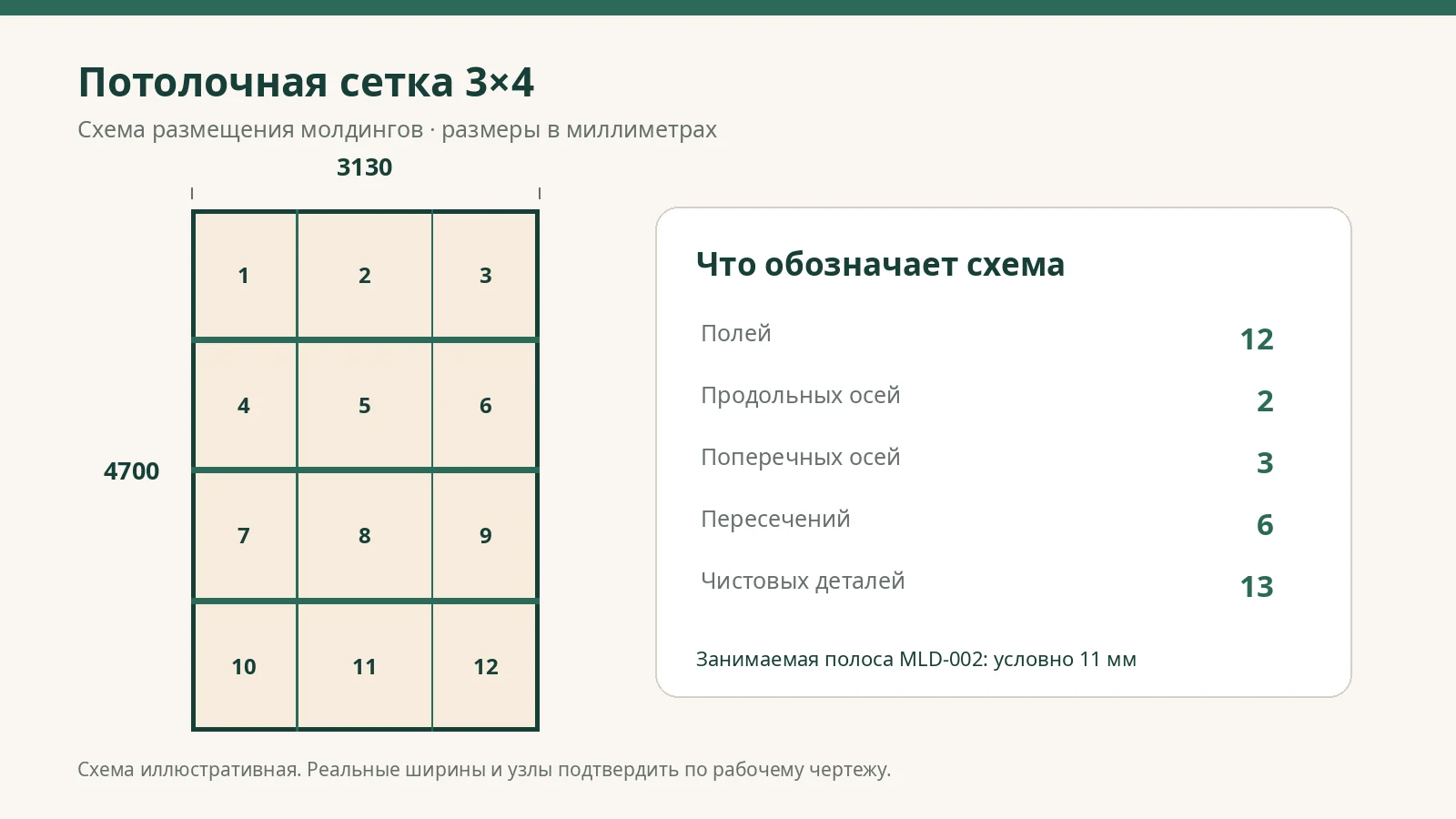
On the plan, the numbers 3×4 denote three columns and four rows, that is, twelve rectangular fields. This requires only two lines in one direction and three in the other. There will be six internal intersections: each of the three transverse axes intersects both longitudinal ones. The outer rectangle of the room is not included in the molding calculation; it is assumed that a separate perimeter cornice already exists or will be calculated independently.
An overlay molding is placed on the finished ceiling plane. It does not create a deep recess, does not bear the load of the floor structure, and does not replace the suspended ceiling frame. Therefore, it is more correct to call the result a decorative grid or an imitation of coffered division. The name “real coffers” would promise a different construction and different costs.
For a room 4700 mm long, four rows with equal division give an axial pitch of 1175 mm. Three columns across the width are formed by marking two longitudinal strips. In the training example, their position is chosen so that the side free fields are equal—950 mm each. The central field differs in width because the two longitudinal strips occupy part of the total width. This is a deliberate composition, not a division error.
The number of decorative fields and the number of commercial products must not be confused. There will be twelve areas on the ceiling, but the specification lists thirteen finished parts and nine or ten commercial planks. The numbers refer to different stages: twelve describes the pattern, thirteen the cut elements, and the number of planks to purchase depends on the chosen cutting scheme.
The composition is checked from several viewing points. If the room has a large floor-to-ceiling wardrobe, the pattern visible from the sofa may differ from the plan diagram. Sometimes it is worth shifting the grid so that the longitudinal lines do not coincide with the end of the wardrobe or the axis of a large light fixture. Such changes require recalculating the parts before purchase.
Measuring a 4700×3130 mm ceiling: real geometry first
The values 4700 and 3130 mm in our project are training dimensions of the clear working ceiling plane. The real room may differ: opposite walls are not always strictly parallel, and an angle deviation is noticeable on a long straight molding line. You cannot limit yourself to a single tape-measure measurement from one corner to the other.
Measure the length along both longitudinal walls and along the central axis. Measure the width not only at the entrance, but also near the opposite wall and in the middle. Check the diagonals separately. If there is a difference, record it on the measurement sheet and decide whether you will align the pattern relative to the room’s geometric axes, the visible cornice, or the main wall. Automatically dividing a different size into equal parts will not correct the skew.
The next question is what counts as the boundary of the working area. If an existing cornice covers part of the ceiling, the dimensions should be taken between its actual inner faces, not between the walls. For the example, 4700×3130 mm are considered precisely as the final overall dimensions by which the grid is laid out. If they were measured on the plaster before installing the cornice, the bill of quantities will inevitably require recalculation.
Mark all ceiling light fixtures, ventilation grilles, sensors, fire detectors, inspection hatches, and finish seams. Even a 30 mm shift of the molding can prevent removal of a light fixture’s decorative ring or maintenance of a ventilation grille. Perform the check not only on the diagram but also against the actual dimensions of the protruding parts.
Before ordering, mark out the ceiling with painter's tape or temporary lines that will not damage the finish. Look at the room from the door, the window and the main seating position. If the pattern appears shifted because of the furniture, correct the axes now. Once the wooden profile is fixed, it will no longer be so easy to move without leaving marks on the base.
How to position two longitudinal and three transverse moldings
In our example, two longitudinal lines run along the 4700 mm length of the room. They divide the 3130 mm width into three open strips with two occupied molding strips between them. For MLD-002, an occupied width of 11 mm each is conventionally assumed. Then 950 + 11 + 1208 + 11 + 950 = 3130 mm. The result gives equal side margins and a wider central one.
The simplest marking method is to work from one accepted base side. Mark the boundary of the first open field at 950 mm, then the 11 mm molding strip, then the central field of 1208 mm and the second 11 mm strip. The remaining 950 mm should match the measurement at the opposite side. If they do not match, do not hide the difference in the last field; check the original dimensions and the perpendicularity of the lines.
Along the 4700 mm length, three transverse lines form four rows. With even distribution, the nominal axes are at 1175, 2350 and 3525 mm from the chosen end boundary. Keep in mind that the exact visible dimensions of the fields depend on the orientation and visible width of the transverse moldings. These axial values are convenient for initial marking, but they do not replace a drawing based on the faces.
The grid must remain rectangular. To achieve this, first check one long base line, then lay out a parallel one. Draw the transverse axes using a verified right angle. On a long surface, a small angular error can lead to a visible narrowing of the outer fields. This is difficult to correct by eye, especially if the wood differs in color from the ceiling.
For a spatial check, it is useful to mark not only the axes on the ceiling but also the full outlines of the strips. A single marker line looks thinner than the actual profile and does not let you assess whether the decorative pattern will come too close to a light fixture. Painter's tape of a width matching the occupied strip better shows the perceived geometry.
Transverse pieces: why there are nine of them, although there are only three lines
Each transverse line runs across the width of the room, but it should not thoughtlessly overlap the two longitudinal moldings. If a solid crosspiece is laid over an already fixed profile, the intersections will have double height and an untidy step. For a clean pattern, a pre-selected joint type is required: butt-jointing at the end, a precisely cut profile, or another agreed installation detail.
According to the adopted geometry, 950 mm remains between the left edge and the first longitudinal molding, 1208 mm between the two longitudinal moldings, and another 950 mm from the second molding to the right edge. These are three separate finished pieces in each row. Since there are three rows, we get nine elements: three central ones of 1208 mm and six side ones of 950 mm.
The total linear length of the cross elements is 3×(950+1208+950) = 9324 mm. This does not include the six occupied intersection points or sawing losses. This counting rule is correct only provided that the crossbars end at the face of the longitudinal profiles according to the chosen scheme. If the designer decides to use special connecting inserts, the lengths may change.
On paper, mark all nine parts with separate indices: P1-L, P1-C, P1-R for the first line, then similarly for the second and third. This simple labeling reduces the risk of confusing the central crossbar with a side one, especially after pre-painting, when all elements look identical.
There is a nuance with natural oak finishing. The cross and longitudinal parts have different grain directions relative to the light from the window. If the wood pattern should be perceived evenly, make a trial layout of two perpendicular samples. The color from a single coating may appear uneven due to the texture direction and glare. This is not an arithmetic defect, but a significant part of the visual result.
Longitudinal lines: four parts of 2350 mm each and a central joint
Along the length of the room, two continuously perceived strips of 4700 mm each are provided. A factory molding 2400 mm long cannot cover such a distance entirely, so each strip is assembled from at least two parts. The nominal option is to divide it in half: 2350 + 2350 = 4700 mm. Two lines will require four finished parts, and their total linear length will be 9400 mm.
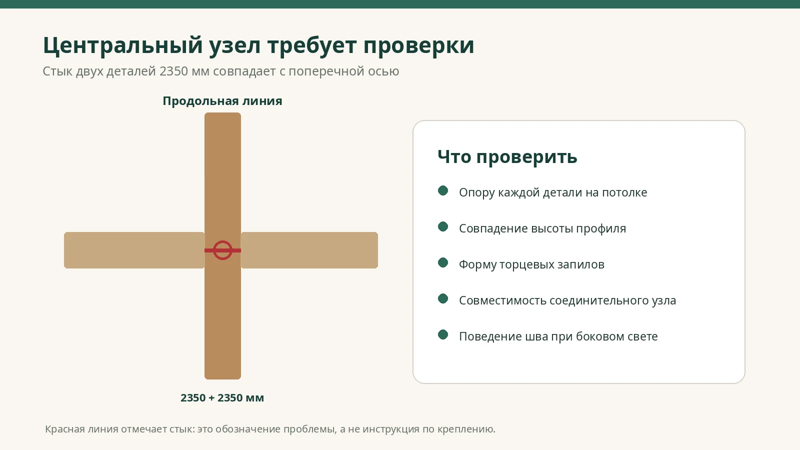
This scheme has a hidden complexity. When the room is evenly divided into four rows, the middle cross line runs at the 2350 mm mark. Exactly there is also the joint of the two longitudinal parts. That is, in the central zone of both longitudinal strips, an ordinary butt joint and the point where the crossbar adjoins coincide. If the material is cut without noticing the coincidence, the installer will have to simultaneously align several ends on the ceiling and hold them in the same plane.
Choose in advance how to handle this node. You can design a connection under an overlay decorative element if it is truly suitable for the chosen profile and does not create a protrusion. You can change the position of the central cross line so that the seam does not fall on the node, but then the four rows will no longer be strictly equal and the marking list will change. Finally, a different connection of the longitudinal parts with reliable support on the base is possible, but it should be verified by a trial assembly.
Simply shifting the central seam by a few millimeters does not always solve the problem. With a commercial strip length of 2400 mm, the total 4700 mm leaves only 100 mm to distribute between the two offcuts and the necessary end treatment. It will not be possible to move the joint location significantly without changing the original lengths. Therefore, any advice to "hide the joint farther from the intersection" must first be checked geometrically.
If the ceiling has level differences, the ends may diverge in height even with the correct cutting angle. Visually, this will appear as a shadow across the long molding. For natural wood that is not planned to be painted with opaque paint, such a step is especially noticeable. Prepare the base, check the fit of the sample, and select the fastening and end-joint treatment together with the contractor based on the actual project.
Bill of materials of thirteen parts: why the total equals 18.724 m
Before choosing a procurement method, it is useful to compile a table of the actual finished parts. It describes what should end up on the ceiling, regardless of which factory strips these parts will be produced from. For the main option MLD-002, we obtain the following specification.
| Group | Length of one part | Quantity | Total length |
|---|---|---|---|
| Longitudinal parts | 2350 мм | 4 | 9400 мм |
| Central crossbars | 1208 мм | 3 | 3624 мм |
| Side crossbars | 950 мм | 6 | 5700 мм |
| Total | — | 13 | 18,724 mm |
Sum check: 9400 + 3624 + 5700 = 18,724 mm, or 18.724 m. This is the length of only the finished sections that form the internal decorative grid. The bill of materials does not include perimeter cornice, painting, glue, additional fasteners, connectors, or transportation costs.
Thirteen parts do not mean thirteen purchased strips. For example, two short side elements of 950 mm each can be obtained from one 2400 mm strip. Conversely, a 2350 mm longitudinal element uses almost all of such a strip, and the remaining offcut is not suitable for another substantial section of this project. Therefore, procurement is calculated not by total linear meters or by the number of finished parts, but by a detailed cutting map.
The table does not include a formal reserve percentage. This is intentional. With four long parts of 2350 mm each, even an additional tenth of the linear meters does not guarantee that the product can be used for the required section: the available length of a specific whole strip matters. A reasonable reserve is determined by the number of suitable products after analyzing likely defects and cutting losses.
In the supply document, specify the finished dimensions separately from the size of the factory blanks. If the order states only "MLD-002, 18.724 m", the order picker may offer a set with a suitable total linear meterage but without the required number of long whole strips. Re-cutting short offcuts will not yield a 2350 mm part.
Option A: the entire set from 2400 mm moldings
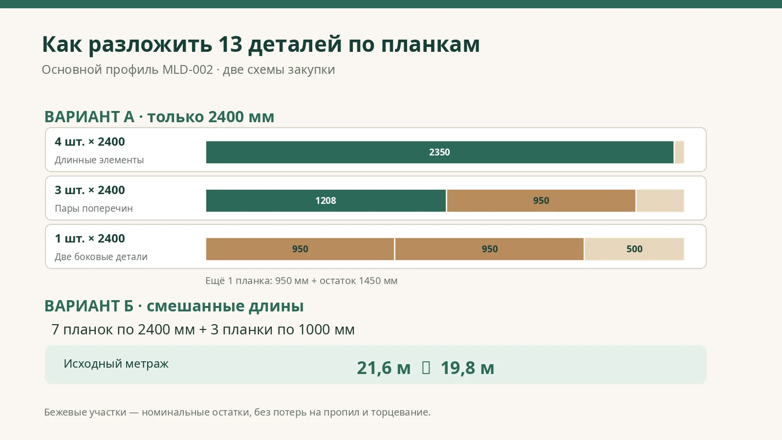
The first scheme is simple to order: all items are of the same commercial length, 2400 mm. But simplicity does not mean the lowest consumption. Four strips go into four longitudinal parts of 2350 mm each. After removing 50 mm from each blank, four finished elements are obtained. The nominal remainder of this group is 200 mm before accounting for saw cuts and end processing.
Three more strips are required for the three central crossbars. From each one, a 1208 mm section and a 950 mm side section can be cut. Their sum is 2158 mm, so each blank nominally retains 242 mm. As a result, we obtain three central parts and three side parts; three side parts of 950 mm remain.
The last three short parts are placed on two strips of 2400 mm length: two of 950 mm are obtained from one, and one from the second. In total, 4 + 3 + 2 = 9 purchased strips are obtained. Their combined length is 9×2400 = 21,600 mm.
| Group of 2400 mm blanks | Quantity | What we cut | Nominal remainder of the group |
|---|---|---|---|
| Long elements | 4 | One part of 2350 mm each | 200 мм |
| Combined crossbars | 3 | 1208 and 950 mm each | 726 мм |
| Remaining side parts | 1 | Two parts of 950 mm each | 500 мм |
| Last side element | 1 | One piece 950 mm | 1450 мм |
| Total | 9 | 13 pieces | 2876 мм |
The total remainder is 21,600 − 18,724 = 2876 mm. This is a mathematical difference, not a promise of obtaining whole usable offcuts of that total length. In several places short fragments will appear, and the final remainder of 1450 mm will stay relatively long. It can be kept for coating samples or future decorative work, but it cannot automatically be considered a useful reserve for any damaged grid element.
A scheme using only long products may be reasonable if meter-long moldings of the required species and quality are not available in sufficient quantity, or if delivery terms make purchasing them unprofitable. A separate large remainder is not necessarily economically useless: for the homeowner it can become material for another small composition. However, in the estimate for this room alone, such a possibility does not reduce the purchase amount.
Option B: seven long and three meter-long moldings
The second scheme uses both confirmed sizes of MLD-002 — 2400 and 1000 mm. Four long products are still reserved for the longitudinal parts. Three more long ones each provide one central crossbar of 1208 mm and one side piece of 950 mm. After that, the bill of materials still contains three side pieces of 950 mm, for which three separate meter-long planks are convenient.
Final purchase: seven products 2400 mm long and three 1000 mm long. In total this is 7×2400 + 3×1000 = 19,800 mm. Compared with the option using only long products, we buy 1800 mm less wood profile for the same thirteen final pieces.
After obtaining a 950 mm piece from a meter-long plank, nominally 50 mm remains. This value is suitable for ordinary arithmetic, but before purchasing it is necessary to check the flatness of the end, possible chips, the required finish trimming, and the kerf thickness. If the manufacturer guarantees only a nominal length of 1000 mm and there is damage at the end, the required 950 mm may be unavailable.
| Parameter | 2400 mm only | Mixed lengths |
|---|---|---|
| Products of 2400 mm | 9 | 7 |
| Items of 1000 mm | 0 | 3 |
| Purchasing linear footage | 21.6 m | 19.8 m |
| Finished linear meters | 18.724 m | 18.724 m |
| Nominal remainder | 2.876 m | 1.076 m |
| Ceiling parts | 13 | 13 |
Saving 1.8 m of source material does not mean a mixed set is always better. It consists of ten commercial planks versus nine; each must be accepted, inspected, and marked if necessary. If short items are out of stock and a separate batch is required, additional logistics costs can change the economics. Therefore, the decision on the scheme is made based on the full confirmed order price, not on a single waste indicator.
Verification of machining allowances before sawing
A long blank of 2400 mm and a finished part of 2350 mm leave a difference of 50 mm. If both factory ends need trimming, this difference is distributed between them. For one part, two clean ends and one separating cut are usually sufficient, but the specific technology depends on the actual condition of the material and tool. A universal waste norm cannot be fixed without verification.
For the pair 1208 + 950 mm, the margin is noticeably larger: 2400 − 2158 = 242 mm. Cuts and trimming are subtracted from this value. Even after reasonable technological losses, it remains possible to shift the cut points if one edge of the blank has a minor defect. But this does not permit ignoring the quality of the middle part: a knot, heterogeneity, or mechanical damage may force the entire cutting plan to be changed.
The most sensitive remain the one-meter blanks for 950 mm parts. Here it is useful to formulate the purchasing condition literally: "Three finished parts 950 mm long are required, from three nominal 1000 mm strips; please confirm the allowable trim." If the answer is negative, you can switch to the fallback scheme with long products without changing the ceiling composition.
It is recommended to make a control cut from one test element rather than processing the entire batch at once. Measure the length of the finished part after end trimming and check the angle, surface flatness, and absence of chips on the relief. After this, the actual technological allowance becomes known, and the cutting map ceases to be merely a paper calculation.
For wood, it is especially important how the cut is made. A dull tool can tear out fibers, especially at the disc exit, and even slight edge crushing will show at the intersection node. If necessary, use a suitable backing and a tool for clean end trimming. Specific settings are selected based on the equipment and the contractor's recommendations; random cutting speed values in the article would be a dangerous substitution for a technological chart.
The cut pieces must be labeled before being lifted to the ceiling. It is convenient to write on an inconspicuous side the model, section, length, and installation direction. If the elements are then painted, the marks are protected or transferred to separate tags. Marks must not be left on the front surface: the marker may show through the finish.
MLD-004: recalculation of central parts and the new total
For the narrower profile, the conditional occupied width of one longitudinal strip is 8 mm. We keep the side light fields at 950 mm in the project. Then the central field is determined by the expression 3130 − 950 − 8 − 8 − 950 = 1214 mm. Each of the three transverse lines will consist of segments of 950, 1214, and 950 mm.
The list of longitudinal parts does not change: four at 2350 mm. There will be three central crossbars at 1214 mm and six side ones at 950 mm. Total 9400 + 3×1214 + 6×950 = 18,742 mm. This is 18 mm more than the MLD-002 scheme's footage, since the inner fields have become wider.
The purchasing groups retain the geometry: four long products for the longitudinal strips, three long ones for the 1214 + 950 mm pairs, three one-meter ones for the remaining short parts. A pair of crossbars occupies 2164 mm out of 2400 mm, leaving 236 mm before saw kerf losses. With the long-products-only option, nine planks are again sufficient.
| Indicator | MLD-002 | MLD-004 |
|---|---|---|
| Section A×C | 22×11 mm | 15×8 mm |
| Central open field | 1208 мм | 1214 мм |
| Longitudinal finished parts | 4×2350 mm | 4×2350 mm |
| Central crossbars | 3×1208 mm | 3×1214 mm |
| Side crossbars | 6×950 mm | 6×950 mm |
| Finished linear meters | 18.724 m | 18.742 m |
| Purchasing in mixed lengths | 7×2400 + 3×1000 | 7×2400 + 3×1000 |
The ability to repeat the purchase composition does not mean the models are fully interchangeable. The MLD-004 profile has a different shape, visible depth and behavior at intersections. Before ordering, it must be applied to the actual ceiling or to a mockup with the lighting that will be used in the room. Otherwise, the economical alternative may turn out to be visually unsuitable.
How much oak and beech moldings cost: four estimates
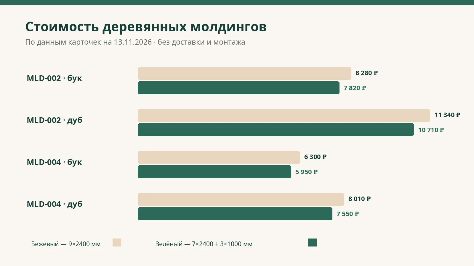
The STAVROS product cards as of November 13, 2026 list the following prices per one factory strip for the wooden finishes under consideration. They are provided for comparing schemes, not as a public offer for a future date: the assortment, stock and cost must be confirmed before payment.
| Product | Beech, 1000 mm | Oak, 1000 mm | Beech, 2400 mm | Oak, 2400 mm |
|---|---|---|---|---|
| MLD-002 | 460 ₽ | 630 ₽ | 920 ₽ | 1260 ₽ |
| MLD-004 | 350 ₽ | 440 ₽ | 700 ₽ | 890 ₽ |
For MLD-002 in beech, nine long planks cost 9×920 = 8,280 ₽. A mixed set costs 7×920 + 3×460 = 7,820 ₽. The savings from a combined purchase equal 460 ₽. For oak, the comparison is 9×1260 = 11,340 ₽ versus 7×1260 + 3×630 = 10,710 ₽, a difference of 630 ₽.
For MLD-004, the beech option with nine long planks costs 9×700 = 6,300 ₽, while the mixed option costs 7×700 + 3×350 = 5,950 ₽. The oak option: 9×890 = 8,010 ₽ versus 7×890 + 3×440 = 7,550 ₽. Here the differences are 350 and 460 ₽ respectively.
| Set option | Beech | Oak |
|---|---|---|
| MLD-002, 9×2400 mm | 8280 ₽ | 11 340 ₽ |
| MLD-002, 7×2400 + 3×1000 mm | 7820 ₽ | 10 710 ₽ |
| MLD-004, 9×2400 mm | 6300 ₽ | 8010 ₽ |
| MLD-004, 7×2400 + 3×1000 mm | 5950 ₽ | 7550 ₽ |
These figures describe the cost of wooden mouldings only. They do not include fasteners, finishing compounds, cutting and installation services, additional connecting pieces, transport to Lipetsk, or packaging. If the inspection reveals an unusable section, or the customer decides to allow for a reserve, the amount will change. It is incorrect to compare a finished ceiling using only the four numbers from the table.
With the same procurement method, MLD-004 turns out to be cheaper than MLD-002. For example, a mixed beech set is 1870 ₽ cheaper. However, the profiles differ in size, and these are different decorative solutions. The price per millimetre of section cannot determine which pattern better suits the room; the final decision requires a trial viewing.
Six intersections and two joints: what the installer must decide
The grid has two longitudinal and three transverse axes, so there are exactly six internal intersection nodes. Each node connects elements running at right angles. In a surface-mounted design, the top surface of all parts must form a coherent pattern without random height differences. Laying one profile on top of another without a special design solution means creating a thickening at the intersection; this is especially noticeable in side lighting.
First of all, decide which line will be perceived as continuous. In the cutting plan given, the longitudinal lines are considered continuous: the transverse parts are brought up to them from both sides. This solution is convenient for calculating the finished linear metreage, but it requires careful finishing of the ends. On a relief profile, an ordinary straight cut may expose the internal section and a sharp change in the pattern. You need to decide in advance whether a visible end is acceptable, whether shaped fitting is required, or whether another connecting technique is planned.
The most problematic section is the middle transverse axis. Here the joint of two longitudinal lengths of 2350 mm coincides. In one place, the ends of several parts meet at once. If you try to hold them together only with adhesive contact to each other, the connection may prove unreliable. All parts should be fixed to a suitable base using an agreed technology; the end joint must not become the only load-bearing element.
A full-size mock-up of one intersection is useful for approval. Cut short samples from the chosen profile, place them at a right angle and check the heights, the abutments and the shadow. Carry out the same check under the actual light fixture or a portable light source. If the node looks untidy on the table, it will not become neater on the ceiling. After testing, you can fix the shape of the cuts and apply it to the remaining five intersections.
When working with with oak moulding MLD-002 it must be remembered that a chip on the front edge is harder to hide with a transparent finish. For painted beech, whether filling and concealing the joint is acceptable depends on the finishing system. Any filling should first be tested on a sample, not on the finished ceiling. Individual decorative overlays for intersections should not be bought based on a similar photograph: compatibility must be documented or confirmed by a trial assembly.
Ceiling base: when a decorative grid is possible at all
A flat surface in the photo does not indicate a strong base. In residential buildings, the ceiling may be concrete, plastered, drywall, or a stretch fabric. Each option requires its own fastening solutions. A massive wooden piece on the ceiling must not be held solely by weak paint, peeling putty, or wallpaper.
If the base is concrete, first check its condition, the adhesion of the finishing layers, and the permitted fastening options. If it is drywall, you need to know the location of the frame or the provided embedded supports. You cannot assume that any thin wooden molding can be safely glued at any point of a suspended structure. The load and method of fixation are agreed with the installer and, if necessary, with the ceiling system manufacturer.
A stretch fabric is a separate case. A rigid wooden profile cannot be attached to it in the usual way. If the decorative mesh is part of the project, pre-designed load-bearing elements or another solution are needed that does not damage the fabric or disrupt its operation. With an already installed stretch ceiling, it may be more reasonable to abandon such an idea than to look for a random adhesive "for all surfaces."
Before starting work, conduct a simple inspection. There should be no wet spots, active cracks, peeling, or unstable finishing areas on the ceiling. Check flatness with a long rule or a suitable measuring tool. If there is a sag along the installation line, a straight wooden molding may either not fit against the ceiling or visibly follow the unevenness. Forcing it into place without calculation creates unnecessary stress in the part.
Minor unevenness can be corrected by the method chosen by the installer, but it cannot be ignored when preparing the estimate. Preparing the base, priming, leveling, and waiting until the materials fully cure can cost noticeably more than the moldings themselves. Therefore, saving between two purchasing options should not push you to skip the necessary preparatory operations.
For a residential room, the operating conditions are especially important. Wood reacts to changes in temperature and humidity, so installation onto a surface that has just dried after wet work, without monitoring conditions, is undesirable. The specific waiting times are determined by the material, coating, base, and manufacturer's instructions. A universal promise that "you can glue it the next day" would be unreliable here.
How to fasten wooden moldings and which mistakes to avoid
The choice of fastening begins with the "product — base" pair, not with the most popular brand of adhesive. You need to understand how flat and strong the surface is, whether there is a factory coating on the back of the profile, and whether the chosen compound is permitted for ceiling placement of a wooden part. Unlike wall decor, a mistake overhead cannot be considered purely aesthetic.
For adhesive installation, find out whether the compound is suitable for the specific wood species and type of base, what the permissible load is, and whether temporary pressure is needed until strength is reached. If mechanical fixation is required, its installation method must prevent cracking of the thin profile and damage to hidden utilities. The location of fastening points is assigned by the installer after studying the actual cross-section and ceiling structure.
Do not independently transfer screw sizes from instructions for massive cornices to the small MLD-004. Its cross-section is only 8 mm along one axis, and a poorly chosen fastener can split the wood. Even for a larger MLD-003 solid wood moulding a separate verification of the mounting method is required: an increased size alone is not a strength calculation.
Mark out the elements before applying adhesive, and do not try to correct a positioning error by pressing down a piece that has already set. It is useful to first do a dry fit of the entire run, compare the position of the ends, and only then fix them in a specific sequence. If there is a gap, first establish the cause: a measuring inaccuracy, warped material, or a cutting error. Adding a thick layer of adhesive does not turn incorrect geometry into correct geometry.
After installation, check not only the appearance but also the accessibility of the ceiling service elements provided for. If a section of the grid must be removed to repair a light fixture, this solution must be planned in advance, not discovered after the final painting.
Light fixtures, ventilation and ceiling pattern lines
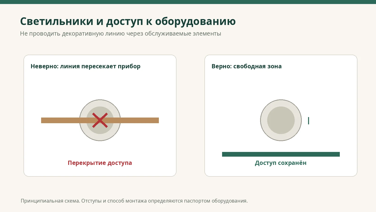
On the 3×4 plan, the lines appear independent of the equipment. In a real room, there may be a chandelier in the center and spotlights or ventilation grilles near the walls. The moulding must not be allowed to cover the fixture's mounting plate, its ventilation gaps, its removable ring, or access to the wiring connections.
If the central light fixture falls on the longitudinal or transverse axis, there are several options. You can adjust the position of the grid, change the number of fields, or leave a separate free zone around the light fixture. But all three options will change the pattern, and sometimes the length of specific parts. The calculated 18.724 m applies only to the original version without such breaks.
Check the actual depth and direction of the light output. The thin MLD-004 produces a less pronounced shadow than a taller profile, but when the light source is positioned almost along the plane, even a small unevenness or a poor joint can become noticeable. Because of this, a trial check under artificial lighting is sometimes more important than evaluating the pattern in daylight.
Be especially careful with light fixtures that generate heat. Do not place wood directly against the heat zone, do not block ventilation, and do not modify the fixture's design. The required clearances are set by the light fixture's documentation and its installation conditions, not by an aesthetic desire to "hide the gap." If the required grid cannot be installed safely, you should change the pattern or omit that section of moulding.
The project must show the ceiling fixtures at the same scale as the decorative lines. On the drawing, each element is marked with its actual dimensions, not just a symbolic icon. This makes it clear whether an additional offset is needed before cutting the materials.
How to align the inner grid with the ceiling cornice
The existing perimeter framing is not included in the moulding estimate. But during installation it cannot be ignored: the transverse and longitudinal lines must end neatly at the inner edge of the cornice or at a specially chosen offset. Ragged short ends near the perimeter will be noticeable regardless of how well the central part of the composition is executed.
If there is no cornice yet, you can consider separately wooden ceiling cornice KZ-004. This is a standalone profile with its own 60×60 mm cross-section and separate commercial lengths. It cannot be included in the overall MLD estimate without a new measurement, calculation of angles and confirmation of junction compatibility.
For the perimeter, length is not the only thing that matters. The cornice can cover several centimetres of the ceiling plane and thereby reduce the working width and length of the grid. If the stated 4700×3130 mm were measured before the cornice was installed, the field dimensions will change once it appears. Conversely, if this is already the finished working area after framing, the previous schedule remains the starting point.
Another mistake is choosing a cornice that is too deep and a very thin inner grid independently of each other. In such a composition the perimeter may visually dominate, and the lines inside will become almost invisible. A good approach is to compare two samples on the same ceiling: step back to the door and assess not the thickness of each element separately, but the ratio of large and small lines.
If the future finish involves clear lacquer, check the species and tone of the cornice relative to the mouldings. Matching the word "oak" in two product cards does not guarantee a visually identical colour after finishing. Sometimes it is wiser to make the cornice painted to match the ceiling and leave the inner grid in wood. This choice depends on the interior, but it must be made before purchasing the coating.
Finishing and care: how not to spoil the pattern after installation
On a flat ceiling plane, recurring finish defects are especially visible: lacquer drips, unevenly painted ends and shiny spots next to joints. Therefore the finishing method should be chosen before cutting and fastening. Some operations are more convenient to perform on individual strips, leaving neat finishing of the joints until after installation. Fully finished lacquered elements are also acceptable, but they are harder to touch up invisibly after trimming.
If a transparent finish is planned, it is worth showing the installer an end-grain cut in advance. Exposed end-grain wood may absorb the finish differently than the longitudinal surface. Without preparation, the joint area will be darker and draw attention. The choice of primer and lacquer should match the selected wood species and the finish manufacturer's recommendations.
For a painted grid, the transition from the ceiling surface to the molding can be handled with contrast or a single tone. Contrast better emphasizes the field layout, but makes any misalignment more noticeable. A single color creates a calmer pattern through shadows. If the main goal is to achieve an unobtrusive division of the ceiling, MLD-001 molding with a slim profile deserves comparison on a sample, but its own width must be re-transferred to the layout.
After installation, care for ceiling wood decor is usually limited to careful dust removal with suitable dry or slightly damp products compatible with the finish. Do not use aggressive solvents and avoid prolonged wetting. If the ceiling is located near a kitchen or sources of high humidity, the suitability of the material and finish should be assessed additionally.
For possible repairs, it is useful to keep a record of the wood species, article number, batch, and the name and color of the finish. Then, if a damaged part needs to be replaced, it will be easier to find a suitable material. One carefully labeled spare strip is sometimes more useful than a bag of small offcuts whose origin no one remembers.
When it is better to avoid such a grid
Not every ceiling needs twelve decorative fields. If the room is already divided by large beams, ventilation ducts, and light coves, another dense grid may make the surface feel restless. Instead, you can choose a single frame or two main longitudinal lines. This solution will reduce the number of nodes but will require its own specification.
If the base is insufficiently strong or there is no acceptable method for ceiling mounting of wooden parts, the purchase should be postponed. The lack of a structural solution cannot be compensated for with more expensive adhesive or a large number of random fasteners. A safe, proven technology must come first, and then the final order of moldings.
If the room has a significant skew or hidden utility routes in the area of the planned fastenings, first change the geometry or the method of installing the decor. Installing rigid, straight elements on a poorly surveyed ceiling can result in the cost of redoing the finish. In such cases, a modest pattern often proves to be a better solution than trying to preserve a 3×4 grid at any cost.
You should not buy a full set just for a small reduction in the cost of one strip. Short parts may be economical in terms of cutting, but may not suit current availability or the batch's finish. The right choice is the scheme that can be fulfilled from agreed products with predictable geometry and an acceptable cost for the whole project.
How to order a set with delivery to Lipetsk
After approving the working drawing, prepare a short request. It must include the delivery city — Lipetsk, the article number, material, type of finish, quantities of each size, and an attached list of finished parts. For the mixed scheme MLD-002, the entry will be simple: seven strips 22×11×2400 mm and three strips 22×11×1000 mm, all in one selected species and agreed quality.
Before paying, confirm the actual cost of the entire batch, the possibility of supplying it with the same material, and the packaging and delivery conditions for long-length items. Do not confuse the stock status of individual options with confirmation of the entire order. If the required one-metre strips are unavailable, request two calculations: a mixed set and nine long ones. Compare not only the cost of the wood, but also transportation, packaging and the estimated reserve.
The purchase and transportation conditions are set out in the section payment and delivery STAVROS. The lead time and rate for a specific address in Lipetsk Oblast must be confirmed separately; a local warehouse or showroom in Lipetsk is not claimed by this text. Upon receipt, inspect the packaging, then check the quantity, article numbers, dimensions and condition of the face edges before starting to cut.
If the buyer is comparing not only the main profile but also another shape, they can look at MLD-028 moulding in oak and beech. It has a different cross-section and a confirmed length of 2400 mm; the calculated mixed scheme with one-metre parts cannot be used for it. Other products are conveniently found in the section solid wood millwork.
It is useful to attach the final cutting plan to the request and note who will do the cutting: the seller or the installation organisation. If the strips are to be supplied whole, the finished dimensions are information for the contractor, not a requirement to cut everything at the warehouse. If the supplier offers pre-cutting, agree the tolerances, the jointing scheme and the marking procedure for each part.
Frequently asked questions about wooden ceiling moldings
Can MLD-002 be replaced with MLD-004 without changing the drawing?
No. The outer cross-section dimensions differ, so the width of the strips and the length of the transverse parts between them change. For the adopted layout, the central crossbar increases from 1208 to 1214 mm. Even if the number of purchased planks remains the same, the installation schedule and intersection details must be updated.
Why are there thirteen parts in the specification instead of twelve?
Twelve is the number of open rectangular fields. The decorative lines consist of four long and nine transverse finished parts, that is, thirteen in total. With combined purchasing, there will be ten commercial planks, since some yield two parts each.
Is one 2400 mm plank enough for a 2350 mm part?
Nominally yes: 50 mm remains. In practice, you need to check the condition of both ends, straightness, the available clean length, and the cut width. If the blank has a defect, the required part may not be produced. Therefore, before purchasing in full, it is advisable to discuss machining allowances.
Why is the saving with a mixed order not always guaranteed?
In the calculated cost of the wood, the mixed option is cheaper, but the order may have a different price for packaging, delivery, and configuration. If suitable short planks are unavailable, their production or separate transportation can change the total amount. Compare the confirmed order estimate as a whole.
Can solid wood moldings be used on a stretch ceiling?
You cannot assume that they can be glued directly to the canvas. A separate structural scheme with permissible supports, designed for the specific ceiling system, is required. If no such scheme exists, mounting a wooden grid on a stretch ceiling is not recommended.
Is it mandatory to use oak if a visible texture is needed?
No, beech is also natural wood. The choice depends on the desired texture, color, finish, and samples from the specific batch. If the interior calls for opaque painting, it is worth comparing the final cost and the quality of the prepared surface, not just the appearance of the unfinished plank.
Can three one-meter moldings be replaced with one long one, and can offcuts be used?
One 2400 mm plank accommodates only two 950 mm pieces, but not three: 3×950 = 2850 mm even before accounting for the saw kerf. For the three remaining side pieces, you will need two long planks or three one-meter planks. This is exactly where the difference between purchasing schemes arises.
How can I tell whether the price in the article is current?
The figures in the table refer to a check on November 13, 2026. Before ordering, open the MLD-002 and MLD-004 product pages, select the material and length, and request confirmation for the entire batch. Do not treat the given values as a permanent fixed price.
Read also
If what is needed is not a calculation for a specific purchase but an overview of the structure of a more complex ceiling, the following article is useful “Coffered ceiling: moldings, cornices, and STAVROS decor”. It explains the principles of decorative ceiling systems but does not replace the thirteen-part bill of materials for this project.
The material will be useful for preparing working nodes and checking the shape of profiles “Moldings for Architects: Profiles and Nodes”. A broader look at beams and ceiling compositions is given in the article “Wooden Ceiling Décor: Beams, Coffers and Rosettes”.
Buy STAVROS solid wood moldings for a ceiling grid
For a room with a working ceiling plane of 4700×3130 mm, the MLD-002 calculation comes to 13 finished parts with a total length of 18.724 m. Based on the accepted dimensions, a mixed option of seven 2400 mm strips and three 1000 mm strips is more economical. The alternative MLD-004 gives a footage of 18.742 m with the same number of commercial items, but with a different cross-section and visual character of the line.
The final purchase begins not with arithmetic, but with an agreed node of six intersections, verification of the ceiling base and confirmation of the finished dimensions. After that, you can create a specification and order wooden molding MLD-004 in beech or oak or the main MLD-002, checking the current price and delivery to Lipetsk. The goal is not to buy more strips, but to actually assemble a level and safely fixed ceiling pattern from the ordered material.