Article Contents:
- KZ-004 60×60 mm: what exactly is being purchased
- Why a product page is not enough for a coffered grid
- Why square 60×60 mm does not prove decorative symmetry
- Why the material is chosen before the final cutting
- Correct calculation based on physical lines
- Why 116 m is not yet the final order
- Why this system is more convenient for revisions
- Why the axis is not equal to the finished length of the part
- Why the main line should not be automatically cut at every intersection
- When the main line can still be split
- What to store in the main line schedule
- What to fix on the working section
- Why A=C equality does not mean four-way symmetry
- Why the butt joint must be checked before the cross joint
- What should remain after the layout
- Why the contour corner and the T-joint cannot be considered the same task
- Why two 45° cuts are not a universal solution
- The main rule of the T-joint
- When the T-joint becomes a separate production part
- What can go wrong at the center of the cross joint
- Why four mathematically precise cuts still don't prove joint quality
- When a cross joint can change the entire cutting logic
- Why the number of joints affects the commercial estimate
- What the mockup must confirm
- Why an MDF sample doesn't replace testing a batch of oak
- What to keep after approval
- What a finished-section entry looks like
- Why node code matters even with the same length
- What the comparison of “12 lines vs 58 spans” gives
- When the number of parts grows even more
- Why “start/end” is especially important for natural wood
- When left/right does not need to be encoded
- Why “the crossbar will hide the joint anyway” is a bad argument
- Example of a long part 2500 mm
- Parts 2380 mm
- Bundle 1840 + 720
- Parts 560 mm
- Preliminary total of the example
- Why simple division can show a different number
- Part 2380 mm
- Bundle 1840 + 720
- Why a 200 mm difference changes more than just consumption
- Preliminary version for MDF
- Preliminary version for solid wood
- Where to choose straight joints
- Why this affects joints
- Why equipment should not dictate random cutting
- Why this separation
- When contour and grid can be combined in one cutting layout
- What must be left on the label
- Why the version matters
- When it is enough to label the pack rather than each part
- Why the frame can be installed before the mesh
- Why assemblies are best not handed out loose
- How to issue material to the workshop
- Why several meters of short offcuts do not replace a whole strip
- How to maintain an offcut bank
- Why material and finish must not be mixed in a reserve
- Example for 20 solid wood planks
- Why the number of frames cannot be honestly stated for 20 MDF without confirmation
- Why the same number of planks does not mean the same logistics
- Why the total piece count is insufficient
- What is added after pre-cutting
- What to do if a mixed batch is already on site
- What to do if different materials accidentally meet on the same line
- How to check the first 2×2 cells before launching the entire grid
- A 10 mm system error scales beyond just meters
- What happens if one transverse line is removed from the grid
- If one main line is added, you can't just add 12 meters
- A reverse audit of 116 meters helps find double counting
- How to compare the price of two materials correctly
- Edge case: one main line changes material in the middle of the hall
- Why the same grid in two halls should have separate codes
- 15 mistakes that are especially dangerous in the KZ-004 ceiling grid
- How to process a reorder
- Before reordering, be sure to recalculate the actual remaining stock
- When KZ-004 cannot yet be purchased in bulk
- When another profile may be more sensible
- Checklist before payment
- What to send to the STAVROS manager for a batch calculation
- Useful STAVROS pages
- General wholesale anchors in a commercial order
- Final ordering algorithm
- What size is KZ-004?
- What is the length of KZ-004 in MDF?
- What is the length of beech and oak?
- Can a coffered ceiling be calculated by the perimeters of all cells?
- Is KZ-004 symmetrical due to its 60×60 size?
- How do you connect KZ-004 at a T-junction?
- How do you make a cross intersection?
- Is it mandatory to make a layout?
- Can the main line be cut at each junction?
- Where should straight joints be placed?
- How do you use the leftovers?
- How do you calculate the reserve?
- What data should be sent to the supplier?
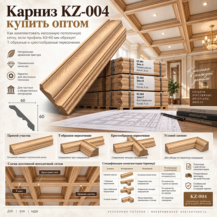
In a large hall, the designer divided the ceiling into rectangular fields and used a single KZ‑004 60×60 mm profile for the outer contour and the internal grid. On the plan, the solution looks like a set of identical coffers. The most dangerous purchasing mistake is to take the perimeter of each rectangle, add up all the numbers, and order the resulting linear meterage. With this method, the shared boundaries of adjacent fields are counted twice, and T-shaped and cross intersections are not addressed at all.
The correct wholesale logic works differently:
ceiling plan → actual grid axes → outer contour → continuous main lines → cross bridges → T-junctions → cross junctions → full-size sample → finishing parts → cutting map 2400/2600 mm → number of whole planks → marking → reserve → order.
The main rule:
the coffered composition is calculated by the physical lines of KZ‑004 and approved junctions, not by the sum of the perimeters of the decorative cells.
At the same time, KZ‑004 should not be perceived as a ready-made factory coffered ceiling system. This is a specific design application of the selected cornice. Before purchasing, it is necessary to confirm the orientation of the actual profile and the technology of the T- and cross-shaped connections.
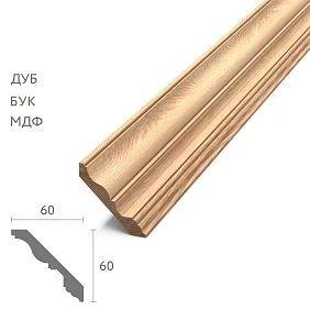
KZ-004 60×60 mm: what exactly is being purchased
The current STAVROS product page confirms three versions of KZ‑004. The cross-section is 60×60 mm in all cases, and the commercial length depends on the material.
| Execution | Section | Product length | What to consider |
|---|---|---|---|
| MDF | 60×60 mm | 2600 мм | Separate cutting map; preparation for enamel |
| Beech | 60×60 mm | 2400 мм | Separate 2400 mm map |
| Oak | 60×60 mm | 2400 мм | Separate 2400 mm map and natural finish inspection |
The sanding quality is stated as “Prestige”. You can check the current version, availability, and price on the product page Buy cornice KZ-004.




Why a product card is not enough for a coffered grid
The card confirms the geometry and material of the source moulding. It does not answer which line in your cross junction must be continuous, where to place a straight joint of a run 6–12 m long, and how the center of the cross should look. These decisions belong to the project.
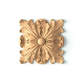
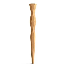
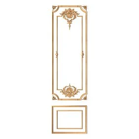
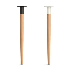
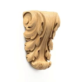
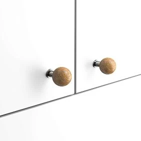
Our factory also produces:

Why 60×60 mm squares do not prove decorative symmetry
Equality of the numbers A and C means equality of two overall dimensions. From this one cannot automatically conclude that the decorative profile pattern is the same at any 90° rotation. Before designing the grid, you need to look at the actual cross-section and determine the face orientation.
Get Consultation
Why the material is chosen before the final cutting
The difference between 2600 and 2400 mm seems small — 200 mm. But a 2500 mm part in MDF can potentially be made solid, while from a standard oak or beech plank of 2400 mm it can no longer be. This means that changing the material can change the visible joints of the entire grid.
Why summing the perimeters of the coffers overestimates the amount of material
Consider a ceiling 8×12 m. Suppose the designer divides it into 24 identical fields: four fields across the width and six along the length. For this, inside the outer contour, three internal longitudinal lines each 12 m long and five internal transverse lines each 8 m long are needed.
Each decorative cell has a nominal size of 2×2 m. If you calculate the perimeter of each of the 24 cells separately:
perimeter of one field = 2 + 2 + 2 + 2 = 8 m.
24 × 8 = 192 m.
But 192 m is not the actual length of the mesh. Internal shared boundaries are counted twice.
Correct calculation by physical lines
Outer contour:
2×12 + 2×8 = 40 m.
Three internal longitudinal lines:
3×12 = 36 m.
Five internal transverse lines:
5×8 = 40 m.
Total:
40 + 36 + 40 = 116 m.
The difference:
192 − 116 = 76 m.
That is, the sum of the cell perimeters in this example overstates the original linear meterage by 76 m even before accounting for cutting, straight joints, nodes, and reserve.
Why 116 m is not yet the final order
This is only the length of the axes of the decorative system. The final purchase depends on exactly how the T- and cross nodes are arranged, where the ends of the parts run, and how 116 m turns into specific segments that must fit into 2400 or 2600 mm profiles.
First we draw the grid axes, not individual rectangles
For purchasing, it is better to think of the ceiling as a system of lines. It is convenient to introduce three groups:
- K — outer contour;
- M — longitudinal main lines;
- P — transverse lines and crossbars.
For example, 8×12 m:
- K‑01…K‑04 — the four sides of the outer perimeter;
- M‑01…M‑03 — three main lines of 12 m each;
- P‑01…P‑05 — five transverse lines of 8 m each.
These are twelve logical lines before splitting into product parts and nodes. They are what form the 24 decorative fields.
Why this system is more convenient for revisions
If the designer removes one transverse line, there is no need to recalculate the perimeters of all cells. It is enough to change P‑03, recalculate the number of nodes on it, and update the corresponding parts.
Why the axis is not equal to the finished length of the part
The axis describes the position of the line in the composition. At a T-node or cross junction, the finished part may end earlier, continue through, or enter a special node. Production dimensions appear after the connections are approved.
What counts as one continuous main line
If M-01 passes through six 12 m long fields, this does not mean six independent 2 m parts. Architecturally, the line can be perceived as continuous. Then the task is to assemble a 12-meter main line from standard planks with pre-selected straight joints.
Why the main line should not be automatically cut at every intersection
On M-01 there are five transverse lines. If every cross node is automatically considered a break, one main line will turn into six short sections. This can increase the number of ends and visible joints without an architectural reason.
When the main line can still be split
If the approved node is designed this way, if the material physically requires a separate part, or if the project specifically ties the joint to an intersection. The decision is made on the sample.
What to store in the main line schedule
| Code | Logical length | Material | Nodes | Straight joints |
|---|---|---|---|---|
| M‑01 | 12,000 mm | As per project | U-K × 5 | By cutting |
| M-02 | 12,000 mm | As per project | U-K × 5 | By cutting |
| M-03 | 12,000 mm | As per project | U-K × 5 | By cutting |
The face orientation of KZ-004 must be fixed before designing the joints
Equal dimensions of 60×60 mm create a dangerous illusion: that the profile can be rotated 90° without changing the pattern. For decorative trim, this cannot be assumed automatically. You need to open the section drawing or take a physical sample and determine which side faces the ceiling, which forms the visible face, and how the relief reads when rotated.
What to record on the working section
- the side facing the base;
- the face side visible from the room;
- the top and bottom edges;
- the direction of the decorative relief;
- the orientation within the contour;
- orientation in the main line and the crossbar.
After that, a conditional orientation arrow can be used in the project. It is especially useful at cross nodes: the four lines must meet not only by coordinates, but also by a single rule of the face pattern.
Why equality A=C does not mean four-way symmetry
The overall square describes the size, not the decorative pattern. If the profile has a concavity, chamfer, step, or another asymmetric shape, a 90° rotation changes the appearance. Therefore, any cross calculations performed on a conditional 60×60 square without the actual cross-section remain preliminary.
The first mandatory layout is the straight section KZ-004
Before complex T- and cross intersections, it is useful to assemble a simple straight fragment 500–1000 mm long. It answers the basic questions that are almost invisible on the plan.
Checked:
- actual profile orientation;
- line of junction to the ceiling;
- lower visible edge;
- shadow depth;
- material finish;
- how the joint of two planks reads on a straight run.
Why the straight joint should be checked before the cross joint
A large grid will still be assembled from 2400 or 2600 mm planks. A main line 8–12 m long inevitably has straight connections. If even a simple joint turns out noticeable or requires special treatment, this technology needs to be known before calculating all the lines.
What should remain after the mock-up
Not only a photo, but also a working record:
KZ‑004 / material ___ / orientation O‑01 / straight joint S‑01 / finish ___ / approved.
This way, subsequent nodes use an already verified base.
The second mock-up — a regular corner of the outer contour
The K‑01…K‑04 contour forms four corners. Before developing the T-nodes, it is useful to check the regular corner joint of the selected material.
You need to see:
- how the decorative pattern aligns;
- how the joint line looks;
- whether a miter joint or another solution is required;
- how noticeable the end face is;
- how the corner looks under side lighting;
- whether there is a difference between MDF under enamel and natural oak/beech.
Why a contour corner and a T-joint cannot be considered the same task
In a regular corner, two lines terminate into each other. In a T-joint, one line must visually continue, while the other enters it from the side. Therefore, the technology of a regular 90-degree corner does not automatically transfer to a T-joint.
The T-shaped joint should be assigned a separate code
For example, on an 8×12 m ceiling, internal mains and crossbars meet at crosses, while internal lines meet the outer contour at T-shaped junctions. It is useful to introduce a code:
U-T01 — T-shaped junction KZ-004.
The junction must answer at least four questions:
- which line remains continuous;
- where the mullion ends;
- how the end face is finished;
- how the face pattern of the profile is preserved.
Why two 45° cuts are not a universal solution
In a standard rectangular frame, two profiles meet at a corner. In a T-joint, the mullion ends in the middle of another part. The geometry and visual logic are different. A simple attempt to make “two miters” can create a gap, a step, or disrupt the relief.
The main rule of a T-joint
If the main run is designed to read as continuous, there is no need to automatically cut it just because a mullion meets it. First, the physical construction of the junction is checked, then the actual composition of the parts is determined.
When a T-joint becomes a separate production part
If it requires a special end cut, notch, additional element, or other preparation. Then the bill of materials includes not just "P‑02, 920 mm", but:
P‑02 / 920 mm / end U‑T01 on the right.
A cross joint cannot be equated with two T-connections
Four directions meet at the cross. Here it is especially dangerous to draw four miter cuts and consider the task solved. You need to see the center of the joint in the actual 60×60 mm profile.
For the project, the following is introduced:
U‑K01 — cross intersection.
What can go wrong at the center of the cross
- the relief of the four parts does not align;
- a void forms at the center;
- one line appears higher than the other;
- too many seams appear at a single point;
- the decorative pattern changes direction;
- under side lighting, the joint becomes more noticeable than the entire grid.
Why four mathematically precise cuts still do not prove the quality of a joint
Even if the ends meet perfectly at the corners, the face relief may not form a visually cohesive cross. That is why U-K01 is checked not only with a ruler, but also on a finished full-size sample.
When a cross can change the entire cutting logic
If the project decides to keep one main line continuous and break the second line at the crossing point. Then the finished lengths of some parts are preserved, while others are divided. If a special insert or another joint is used at the center, the number of parts changes even more.
In a 4×6 field ceiling, 15 crosses and 16 T-joints appear
For the example with 24 fields, the joints can be calculated even before production detailing.
Three internal longitudinal lines intersect with five internal transverse lines:
3 × 5 = 15 U‑K cross nodes.
Each longitudinal line meets the outer contour twice:
3 × 2 = 6 T‑nodes.
Each of the five transverse lines also has two junctions with the perimeter:
5 × 2 = 10 T‑nodes.
Total:
6 + 10 = 16 T‑shaped nodes.
Plus four regular corners of the outer contour.
| Type | Quantity in the example | What to Check |
|---|---|---|
| U‑90 | 4 | Outer contour corners |
| U‑T | 16 | Junctions of internal lines with the contour |
| U‑K | 15 | Cross intersections of internal lines |
Why the number of nodes affects commercial calculation
Each repeating node requires either identically prepared ends of parts or a separate special element. If U‑K01 repeats 15 times, even a small extra operation becomes serial. That is why it is advantageous to approve the cross technology once before a wholesale order.
A 2×2 control fragment of the field checks the entire system
There is no need to assemble an entire 8×12 m ceiling just for a test. A full-size fragment containing the main situations is sufficient:
- part of the outer or conditional contour;
- straight main line;
- jumper;
- T-shaped junction;
- cross fitting;
- one straight joint of the product strips.
What the layout must confirm
A 2×2 fragment of the field must answer the questions:
- which face orientation of KZ‑004 is adopted;
- what U‑T01 looks like;
- what U‑K01 looks like;
- which line is continuous;
- how the ends of the crossbars are finished;
- where a butt joint is acceptable;
- how noticeable the joints are under design lighting;
- whether the technology can be replicated in series production.
Why an MDF sample does not replace testing an oak batch
The profile geometry is the same, but the commercial length, processing and finish differ. In white opaque enamel, the joint may read differently than in natural oak. If the project changes the material, it is advisable to check the key joints on the selected finish.
What to keep after approval
Photos, a dimensional drawing, the version code and a physical sample of the joint. For example:
HALL‑01 / J‑T01 / J‑K01 / KZ‑004 oak / T‑01 / version R02.
Node codes turn a decorative pattern into a working specification
Once the sample is approved, the grid gets a simple code system:
- U‑90 — standard outer contour corner;
- U‑T — T-shaped junction;
- U‑K — cross intersection;
- U‑O — free end;
- S‑P — straight joint of two commercial planks on the same line.
A node code does not answer the question “what a beautiful pattern,” but a production question: how a specific part ends and what junction should be at its end.
What a finished section entry looks like
For example:
M1‑01 / 2380 mm / start S‑P / end U‑K.
P4-03 / 1920 mm / start U-T / end U-K.
This way, the workshop receives not abstract "12 meters of main line," but real sections with clear terminations.
Why the node code matters even with the same length
Two segments of 920 mm can have different ends: one enters a T-node on the left, the second enters a cross on the right. If pre-cutting includes special end preparation, these parts are no longer interchangeable just because the length matches.
If each node divides the line, the example produces up to 58 separate spans
This is not a mandatory KZ-004 technology, but a useful calculation model showing the scale of detailing.
If we imagine that each line is physically split at every node, we get:
- 3 longitudinal main lines, each intersected by 5 transverse lines → 6 spans each → 18 sections;
- 5 transverse lines, each intersected by 3 main lines → 4 spans each → 20 sections;
- the upper and lower sides of the perimeter each have 3 T-nodes → 4 spans each → 8 sections;
- the left and right sides each have 5 T-nodes → 6 spans each → 12 sections.
Total:
18 + 20 + 8 + 12 = 58 spans.
But this does not mean that 58 independent parts must automatically be manufactured. If the project keeps the main runs continuous, the actual number of production elements will be smaller. The number 58 is useful as an upper guideline for detailing when fully divided by nodes.
What the comparison of “12 lines versus 58 spans” gives
At the architectural level there are only twelve logical lines. At the production level, after the nodes, several dozen parts may appear. That is precisely why a separate schedule must exist between the beautiful ceiling plan and the order.
When the number of parts grows even more
If the straight joints of the commercial planks do not coincide with the nodes, one long main run is additionally divided along the 2400/2600 length. Parts appear that begin and end not at grid nodes, but at the joints of the original planks.
The schedule of finished sections must store the start and end of each part
| Code | Group | Length | Start | End | Material |
|---|---|---|---|---|---|
| M1‑01 | Main run | ___ | U-90 / S-P | U‑K | As per project |
| M1-02 | Main run | ___ | U‑K | S-P / U-K | As per project |
| P2-01 | Jumper | ___ | U‑T | U‑K | As per project |
| K1-01 | Contour | ___ | U‑90 | U‑T | As per project |
This table is already suitable for production cutting. It shows not only the length, but also the function of each end.
Why "start/end" is especially important for natural wood
If a part has a pre-prepared joint or a visible end face, it cannot be rotated arbitrarily. Orientation can become part of the marking.
When left/right does not need to be coded
If both ends are processed identically and the profile is symmetrical in the accepted orientation. There is no need to create extra codes without a production necessity.
The longest continuous parts are calculated first
Long sections have the fewest raw material options. A short bridge of 600–1000 mm can be obtained from various offcuts, while a section of 2300–2500 mm almost always requires a full plank.
Therefore, cutting is planned in the following order:
- long main sections;
- long contour parts;
- long transverse lines;
- medium bridges;
- short end pieces;
- joint parts;
- repair reserve.
Why “the cross-shaped connector will hide the joint anyway” is a bad argument
If assembly U‑K01 is approved as a specific structure, you cannot insert a random short offcut next to it just for the sake of utilization. A butt joint and an intersection assembly are two different things. Combining them is permissible only if it is provided for by the U‑K01 scheme itself.
Example of a long part 2500 mm
In MDF 2600 mm:
2600 − 2500 = 100 mm.
The part can potentially be made as a single piece. The offcut almost certainly does not help the grid.
In oak/beech 2400:
2500 > 2400.
A single-piece part of standard length cannot be produced. This may add a butt joint and change the mating point with the nearest assembly.
The cutting map for MDF 2600 mm is built separately
Let us consider a conditional set of finished parts after the assemblies have been approved:
- 30 parts of 2380 mm;
- 40 parts of 1840 mm;
- 40 parts of 720 mm;
- 60 parts of 560 mm.
This is not a universal KZ‑004 specification, but an example of the method.
Parts 2380 mm
Each one almost completely occupies the strip:
2600 − 2380 = 220 mm.
30 parts block at least 30 original strips.
Combination 1840 + 720
Arithmetically:
1840 + 720 = 2560 mm.
The combination potentially fits within 2600 mm, leaving 40 mm before accounting for the cut. Since a cut is needed between the two parts, the technician must confirm whether the allowance is sufficient. If so, 40 parts of 1840 mm can be paired with 40 parts of 720 mm.
Parts of 560 mm
Four such parts yield:
560 × 4 = 2240 mm.
About 360 mm remains in one strip before accounting for three cuts. For 60 parts, approximately 15 strips will be needed with a four-element layout, if the technology allows such cutting.
Preliminary summary of the example
30 long strips + 40 combined + about 15 for short parts:
about 85 original MDF strips
before reserve, additional units, and actual technological allowances.
Why simple division may show a different figure
Net footage of the set:
30×2.38 + 40×1.84 + 40×0.72 + 60×0.56 = 71.4 + 73.6 + 28.8 + 33.6 = 207.4 m.
Simple division:
207,4 / 2,6 ≈ 79,77.
Mathematics promises a minimum of 80 planks. The practical structure of the example gives about 85 even before the reserve. The difference arises from inconvenient lengths and combination constraints.
The cutting map for beech and oak 2400 mm is built anew
The same set cannot be mechanically recalculated using the 2600/2400 coefficient.
Part 2380 mm
Out of 2400 mm, it theoretically leaves only 20 mm before accounting for the cut and trimming. This is a borderline case: before ordering, you need to check whether the technology allows obtaining a finished length of 2380 mm from a commercial strip of 2400 with the required cuts.
If not, the set of parts itself or the location of the direct joint requires revision. You cannot promise that any part 20 mm shorter than the commercial length is guaranteed to be obtained from it.
Combination 1840 + 720
1840 + 720 = 2560 mm.
It no longer fits within 2400 mm.
You can look for another combination:
1840 + 560 = 2400 mm.
Purely arithmetically, it fills the strip completely, but a cut is needed between the parts. Therefore, without a technological allowance, such a combination may also be impossible. You may have to use 1840 separately and distribute the short parts differently.
Why a 200 mm difference changes more than just consumption
They can change:
- locations of direct joints;
- the number of whole strips;
- the set of useful offcuts;
- the cutting sequence;
- packaging volume;
- repair reserve.
Therefore, changing MDF to oak after the calculation is complete is a new production task.
A 6000 mm long main line is designed as a line with pre-assigned joints
The standard KZ-004 plank is shorter than six meters, so a long main line is always assembled from several commercial products. But the phrase "there will still be joints" does not mean that the connection points can be chosen randomly during installation.
Preliminary version for MDF
Six meters can be made up, for example, from three parts:
2400 + 1800 + 1800 = 6000 mm
or other combinations within 2600. Which option is better depends on the location of U-T, U-K, light fixtures, and visual axes.
Preliminary version for solid wood
With a commercial length of 2400 mm, one of the logics is:
2400 + 1800 + 1800 = 6000 mm.
But if two joints end up next to two adjacent crossbars, the line may visually become too fragmented. In that case, the lengths are redistributed.
Where to choose straight joints
Checked:
- distance to U‑K and U‑T;
- center of the field;
- direction of the main gaze;
- linear lighting;
- light fixtures and suspensions;
- architectural axes;
- the ability to obtain the required length from a commercial strip.
There is no universal rule that “the joint is always at the corner” or “the joint is always in the center of the cell.”
Lighting and ceiling equipment are applied before the cutting plan is issued
The article does not design electrical systems, but the KZ‑004 grid should not be calculated in isolation from already approved equipment.
The following are marked on the plan before the final cutting:
- recessed spotlights;
- linear lighting profiles;
- pendant lights;
- ventilation grilles;
- sensors;
- fire safety devices;
- service hatches;
- other elements that may fall within an axis or node.
Why this affects joints
If the cross fitting already coincides with a light fixture suspension point, adding a straight main line joint nearby may be unwise. The design can move the connection to an adjacent field.
Why equipment should not dictate random cutting
First, the designer determines the permissible relative position, then the production map follows that decision. The installer should not shift the U-K by 100 mm just because it is easier to bypass the fasteners that way.
The outer contour and the inner grid are one product, but two functional groups
There is no need to create two new SKUs in the product database, "KZ-004 contour" and "KZ-004 caisson". Physically, this is one product.
But within the object, it is useful to preserve the designations:
CONTOUR KZ-004
и
GRID KZ-004.
Why this separation is needed
The contour contains U-90 and U-T, the internal lines are U-K and their own straight joints. With the same material, the remnants can be used together, but the installation completeness and marking differ.
When the contour and the grid can be combined in one cutting plan
If the material, finish, orientation, and product length match. Then a short remnant after K-02 can cover P-04. But the code of the finished part must still show its designation.
Marking after cutting must preserve the line and joint type
After whole planks are turned into parts, a single label "KZ-004" is no longer enough. Dozens of similar 60×60 mm offcuts arrive at the site, and without a code the installer cannot tell whether a part belongs to the main line, a jumper, or the outer contour.
Working marking:
HALL-01 / M2-03 / 2380 mm / end U-K.
HALL-01 / P4-01 / 920 mm / U-T right.
HALL-01 / K2-02 / 1840 mm / U-90 left.
What must be kept on the label
- object or hall;
- line code;
- part number;
- the finished length;
- the material;
- finish;
- type of prepared end, if it differs;
- drawing version.
Why the version matters
If after the control fragment U-K01 has changed to P02, the old P01 parts must not accidentally get mixed with the new series. The same length does not make them identical if the ends are prepared using different technology.
When it is sufficient to label the pack rather than each part
If the pack contains completely identical elements of the same length and the same purpose. For example, 20 identical P3-02. If the parts are of different types, individual labeling is safer.
It is better to assemble the installation sequence by functional groups
Instead of one large pack for the "entire ceiling", it is convenient to divide the delivery into installation sequences:
- outer contour;
- main lines;
- cross braces;
- parts of T- and cross junctions;
- separate reserve.
Why the perimeter can be installed before the grid
If the design technology allows this, the perimeter sets the base and makes it possible to check the actual geometry of the room. But the installation of the internal grid must still proceed according to the current layout so that small deviations of the walls do not accumulate in the center of the ceiling.
Why nodes are better not distributed in bulk
Fifteen U‑K crosses and sixteen T‑nodes in the example are repeating series. If special parts or endings are prepared in advance, it is convenient to pack them into separate bags by node type. This reduces the risk that one U‑T part ends up in a cross.
How to issue material to the workshop
Not:
“40 strips KZ‑004.”
But:
“KZ‑004 / MDF / 60×60×2600 / HALL‑01 / cutting M‑01…M‑03 and P‑01…P‑05 / 40 strips.”
This way the workshop understands that the material is tied to a specific card, and is not a free warehouse remainder.
Reserve should be divided by length and function
Weak entry:
KZ‑004 +10%.
It does not answer whether the stock can replace a long main part or only a short jumper.
Four groups are more useful:
- whole strips for long sections;
- medium offcuts for crossbars;
- short parts and offcuts for joints;
- operational reserve after handover.
Why several meters of short offcuts do not replace a whole strip
In stock:
- 800 mm;
- 650 mm;
- 900 mm;
- 500 mm.
Total:
800 + 650 + 900 + 500 = 2850 mm.
But if a 2200 mm long main line part is damaged, all this stock is useless for a solid replacement. The total footage is more than needed, but there is no suitable length.
How to maintain a stock bank
| Group | Whole | 1800+ | 800–1799 | 300–799 |
|---|---|---|---|---|
| KZ‑004 / MDF / O‑01 | ___ | ___ | ___ | ___ |
| KZ‑004 / oak / T‑01 | ___ | ___ | ___ | ___ |
| KZ‑004 / beech / E‑02 | ___ | ___ | ___ | ___ |
Why material and finish cannot be mixed in reserve
MDF stock for enamel does not replace oak with a clear finish. Beech does not replace oak. Even a single KZ‑004 should be stored as several product groups if the project uses different materials or finishes.
Packaging and a large batch affect the real cost of the order
The current KZ‑004 card specifies a rigid packaging frame costing 390 ₽. For solid wood items, the norm is up to two planks per frame; for MDF, packaging is mandatory due to horizontal transportation. It is better to confirm the exact number of packaging units for a specific MDF batch with the seller when placing the order.
Example for 20 solid wood planks
With a norm of up to two items:
20 / 2 = minimum 10 frames
with full filling and if the seller confirms such a configuration for the specific delivery.
Cost of ten frames at the current packaging price:
10 × 390 = 3900 ₽.
This is only an example based on the current card data; the packaging price must be rechecked before payment.
Why the number of frames for 20 MDF cannot be honestly stated without confirmation
The current product page states that MDF packaging is mandatory, but it does not provide a universal maximum number of slats per frame in the open text. Therefore, the article must not invent a figure. The supplier confirms the actual packaging scheme when calculating the batch.
Why the same number of slats does not mean the same logistics
Oak/beech products and MDF have different norms and packaging conditions, and the project may additionally divide the material by halls, phases, and finishes. Full cost:
goods + packaging + delivery + finishing + cutting + reserve + possible repeat reorder.
Acceptance, errors, reorder, and final batch inspection
Before cutting and finishing, each product group is checked.
- KZ‑004;
- cross-section 60×60 mm;
- the material;
- length 2600 or 2400 mm;
- quantity;
- profile integrity;
- straightness;
- ends;
- marking;
- packaging.
Why the total piece count is insufficient
60 MDF and 20 oak were ordered. In fact, 55 MDF and 25 oak arrived. The total of 80 matches, but the project received five 2600 mm slats short. The extra 2400 oak does not automatically replace them.
What is added after pre-cutting
- code M/P/K;
- part number;
- finished length;
- joint type at the ends;
- orientation;
- version.
What to do if a mixed batch is already on site
- stop mass issuance;
- separate MDF, beech, and oak;
- check 2400/2600;
- separate finishes;
- match with zones;
- re-label;
- only then issue for cutting.
What to do if different materials accidentally meet in one line
Do not try to automatically hide the transition with filler, undercutting, or a random joint. First determine whether this is a picking error, a designed material boundary, or a project change. The detail must be agreed upon before irreversible finishing.
How to check the first 2×2 fields before launching the entire grid
After the layout is approved, it is useful not to cut material for the entire hall right away, but to release the first small production batch: the outline of one section and a 2×2 field of the internal grid. It already contains straight lines, T-junctions, a cross intersection, several short parts, and at least one straight joint.
In the first batch, compare:
- the estimated number of parts;
- Actual quantity;
- the usefulness of the leftovers;
- marking speed;
- accuracy of U‑T01;
- accuracy of U‑K01;
- repeatability of face orientation;
- visibility of butt joints after finishing.
If installation shows that every P‑element has to be shortened by the same amount, this is not "manual fitting" but a systematic error in the bill of materials. It is better to correct it in four fields than after cutting 24.
A systematic error of 10 mm scales not only in meters
Suppose that after a trial assembly it turns out that one standard crossbar should be 10 mm shorter. There are 40 such crossbars in the ceiling.
Total difference:
10 × 40 = 400 mm.
In terms of linear meters, this is only 0.4 m. But if 40 parts have already been cut, all of them require reworking. If the error was in the direction of increase, some parts can be shortened. If they are already 10 mm shorter than required, all 40 have to be remade. That is why control by the total number of meters is weaker than control by a standard part.
What happens if one transverse line is removed from the grid
In the example, there were five internal transverse lines of 8 m each. If the designer excludes P‑03, the net axial length decreases by 8 m:
116 − 8 = 108 m.
But the change is broader than a simple difference of 8 m.
At the same time, the following disappear:
- three U‑K cross joints at intersections with M‑01…M‑03;
- two T‑nodes on the outer contour;
- some special end caps;
- parts of P‑03 itself;
- possible straight joints of this line.
Moreover, the bays along the length are no longer identical. Consequently, the ceiling version must be updated entirely at the level of the axial layout, and not merely reduced by eight meters in the estimate.
If one main line was added, you cannot simply add 12 meters
The new longitudinal line M‑04, 12 m long, will intersect all five transverse lines and the outer contour.
She adds:
- 12 m of axial length;
- 5 new cross tees;
- 2 new T-junctions;
- new finishing sections;
- new straight joints depending on 2400/2600;
- new ceiling fields.
Therefore, revising the grid is a change in topology, not just in linear meters.
A reverse audit of 116 meters helps identify double counting
After all parts and whole planks have been counted, it is useful to work the calculation backward. For the original example, the logical axial length should unfold as follows:
- 40 m — outer contour;
- 36 m — three longitudinal mains;
- 40 m — five transverse lines.
If the clean lines master list suddenly shows 126 or 135 m before accounting for special allowances and technological details, look for:
- the line counted twice;
- the contour included both as a cell side and as a separate group;
- one jumper counted simultaneously in P and in K;
- the old version of the line was not deleted after revision.
This is how the reverse check catches table errors before ordering.
How to compare the price of two materials correctly
You cannot compare MDF and oak by the price of a single plank alone
Boundary scenario: one main line changes material in the middle of the hall
If a project uses both MDF and natural wood at the same time, the material boundary must be placed at a pre-defined, clearly understood architectural point. You cannot start M-01 as KZ-004 in MDF 60×60×2600 mm and then, without a dedicated junction detail, continue it in oak 60×60×2400 mm just because the SKU and outer cross-section match.
Before such a change, check:
- matching face geometry in the selected orientation;
- difference in finish and light-and-shadow;
- exact transition point;
- method of direct jointing;
- logic of adjacent T- and cross-junctions;
- separate cutting maps for the two materials.
It is more rational to move the material boundary to where it reads as part of the composition: to a room boundary, an architectural break, a separate ceiling zone, or another pre-approved transition. A random material change in the middle of a continuous run makes repairs and reordering more difficult: the same code M-01 begins to refer to two product groups at once.
Why the same grid across two halls should have separate codes
If hall A and hall B are visually identical but differ in material, lighting, or the length of the edge margins, it is better to use HALL-01 and HALL-02. Then the leftover MDF from the first hall will not automatically become a reserve for the oak of the second, and a local revision of P-03 in one room will not change the schedule of the other.
This keeps coding simple: geometrically identical nodes can retain U-T01/U-K01, while the object ownership of a part is determined by the hall and line code.
15 mistakes that are especially dangerous in the KZ-004 ceiling grid
1. Adding up the perimeters of all coffers. Cause — rectangular fields are easy to measure separately. Consequence — shared boundaries are counted twice; in the example of 24 fields, this gives 192 m instead of 116 m of actual axes. How to prevent — count the contour and internal lines separately.
2. Treating each cell as a self-contained frame. Cause — visually the ceiling consists of rectangles. Consequence — a run that should pass through several fields is artificially split. Prevention — first the M/P/K axes, then the details.
3. Treating KZ-004 as fully symmetrical just because of 60×60 mm. Cause — equal dimensions are perceived as the same pattern when rotated. Consequence — nodes are assembled with the wrong orientation. Prevention — a section drawing and a physical sample.
4. Making a T-node like an ordinary corner. Cause — habit of frame joints. Consequence — the run loses continuity or an unapproved end appears. Prevention — a separate U-T01.
5. Making a cross joint with four random stubs. Cause — mathematically, four lines meet at the center. Consequence — a void, a step, or mismatched relief. Prevention — a full-size U-K01.
6. Do not assemble a control fragment. Reason — the project seems obvious in 3D. Consequence — a mass series repeats one error invisible in the render. Prevention — a 2×2 field fragment before wholesale purchasing.
7. Cut the main line at every intersection. Reason — the desire to simplify the assembly of nodes. Consequence — a long line gets extra ends and joints. Prevention — determine continuous directions at the design stage.
8. First cut the long stock into short crossbars. Reason — short parts are easier to produce. Consequence — later there are not enough solid 2300–2500 mm pieces. Prevention — long parts have first priority.
9. Calculate MDF and replace it with oak without recalculating. Reason — the profile is the same 60×60. Consequence — 2600 mm combinations do not fit into 2400, the joints change. Prevention — a separate material map.
10. Do not code T- and cross nodes. Reason — installers are supposed to "figure it out from the plan." Consequence — parts of the same length get different unlabeled ends. Prevention — U‑T, U‑K, and version.
11. Count the reserve only in meters. Reason — it is convenient to store one number. Consequence — 2.85 m of short offcuts are mistakenly considered a replacement for a 2200 mm part. Prevention — a bank of remnants by lengths.
12. Use a short remnant only because it almost fits. Reason — the desire to reduce waste. Consequence — the part becomes shorter than designed or the node shifts. Prevention — the remnant is selected for the approved part, not the other way around.
13. Combine the contour and the grid without assignment. Reason — physically it is one KZ‑004. Consequence — the contour material goes into short crossbars, and later there are not enough long sides. Prevention — functional groups under a common product code.
14. Place a reorder only by meterage. Reason — "12 m were missing." Consequence — enough meters arrive, but again not the needed lengths. Prevention — reorder by specific M/P/K parts and whole strips.
15. Do not account for the packaging of a large batch. Reason — only the profile price is compared. Consequence — the logistics of solid wood and MDF are underestimated. Prevention — packaging and delivery as separate lines in the commercial calculation.
How to place a reorder
Bad request:
"We were 12 meters of cornice short."
It does not specify which lengths are needed. Twelve meters can be delivered as five short offcuts or several full planks — the result for a long run will differ.
A good request:
KZ‑004 / MDF / 60×60×2600 / HALL‑01 / M3 and P4 / ___ full planks and ___ parts per schedule R03 are required.
Before reordering, be sure to recalculate the actual remaining stock
Checked:
- full planks;
- long offcuts 1800+;
- medium offcuts 800–1799;
- short parts 300–799;
- finished but not yet installed elements;
- repair reserve;
- material held by the installation crew;
- defects and rework.
Only then is the new requirement translated into whole planks.
When KZ-004 cannot yet be purchased in bulk
It is better to pause bulk purchasing if:
- there is only a beautiful render of the coffers;
- real axes have not been built;
- the front orientation of KZ‑004 has not been determined;
- U‑T01 has not been developed;
- U‑K01 has not been developed;
- there is no full-size fragment;
- Material not selected;
- 2400 and 2600 mm are considered the same;
- the quantity is obtained as the sum of the cell perimeters;
- lighting and ceiling equipment are still subject to change;
- the locations of butt joints are not determined;
- the reserve is specified only as a percentage.
At this stage, you can request the budget and availability. But it is too early to release the final batch.
When another profile may be more reasonable
If KZ‑004 in the cross joint creates too massive a center, the orientation of the decorative pattern does not allow a neat U‑K connection, or 60×60 mm overloads a dense grid, the project should consider another profile or a different ceiling geometry. The unification of KZ‑004 should not be more important than the architectural result and manufacturability.
Checklist before payment
| Check | Status |
|---|---|
| KZ‑004 is finally selected | ___ |
| 60×60 mm confirmed | ___ |
| MDF 2600 / beech-oak 2400 separated | ___ |
| Front orientation of the profile is fixed | ___ |
| Outer contour calculated separately | ___ |
| Main lines M‑01… marked | ___ |
| Jumpers J‑01… marked | ___ |
| U‑90 verified | ___ |
| U‑T01 approved | ___ |
| U‑K01 approved | ___ |
| 2×2 field fragment assembled | ___ |
| Lighting and equipment applied | ___ |
| Finished sections added to the list | ___ |
| Long parts calculated first | ___ |
| MDF map 2600 built | ___ |
| Solid wood map 2400 built separately | ___ |
| Direct joint locations approved | ___ |
| Contour and grid have a purpose | ___ |
| Part marking approved | ___ |
| Remnant bank created | ___ |
| Full repair reserve preserved | ___ |
| Packaging and delivery confirmed | ___ |
| Acceptance and reorder format approved | ___ |
What to send to the STAVROS manager for batch calculation
A working request might look like this:
"Please calculate a wholesale batch of KZ‑004 cornice 60×60 mm for the decorative ceiling grid of the project. Material — ___ . The outer contour and the inner grid are separated in the schedule. Longitudinal mains and transverse lines have finished dimensions. T-shaped and cross-shaped nodes are approved on the working sample. The number of initial strips is calculated according to the cutting map 2400/2600 mm. The whole reserve and short offcuts are accounted for separately. Please confirm the current price, availability or production time, packaging and delivery."
Useful STAVROS pages
Specific product — wooden cornice KZ‑004.
The narrow scenario with an already installed acoustic island is covered separately in the article KZ‑004 next to an acoustic ceiling island.
Another standalone scenario — KZ-004 and a floor-to-ceiling kitchen. This new article does not repeat those topics: here KZ-004 has already been selected for an internal ceiling grid with repeating intersections.
General wholesale anchors in a commercial order
If the purchase is placed as building materials Moscow wholesale, via large supplier of building materials, Construction material suppliers Moscow, construction materials suppliers moscow, wholesale building material suppliers or Building materials suppliers wholesale, KZ-004 still remains a separate technical specification.
The same rule applies to wholesale purchase of building materials, building materials at wholesale prices, wholesale sale of building materials, building materials wholesale from the manufacturer, building materials wholesale from the manufacturer, wholesale purchase of building materials, wholesale supplies of building materials, building materials wholesale Moscow, wholesale purchases of building materials, wholesale sale of building materials, wholesale building materials warehouse и wholesale building materials warehouse. These general B2B phrases refer to the overall supply and do not replace the KZ-004 product card.
Final ordering algorithm
CONFIRM KZ-004 → LOCK 60×60 MM → SELECT MATERIAL → LOCK PROFILE ORIENTATION → BUILD THE OUTER CONTOUR AND GRID AXES → CODE M/P/K → CALCULATE U-90, U-T AND U-K → ASSEMBLE THE STRAIGHT SECTION AND CORNER → ASSEMBLE A 2×2 FIELD FRAGMENT → APPROVE U-T01 AND U-K01 → ISSUE THE FINISHED PARTS SCHEDULE → ADD LIGHTING AND EQUIPMENT → SELECT STRAIGHT JOINT LOCATIONS → RESERVE LONG RUNS → BUILD A SEPARATE MAP FOR 2600 OR 2400 → USE SUITABLE OFF CUTS FOR SHORT PARTS → COUNT WHOLE STRIPS → CREATE A STRUCTURED RESERVE → LABEL → CONFIRM PACKAGING → ACCEPT THE BATCH → ISSUE BY INSTALLATION GROUPS → REORDER BY SPECIFIC PARTS AND WHOLE STRIPS.
What size is KZ-004?
Cross-section — 60×60 mm.
What is the length of KZ-004 in MDF?
2600 mm.
What is the length in beech and oak?
2400 mm.
Can a coffered ceiling be calculated along the perimeters of all cells?
No, not for the final purchase. Shared borders of adjacent cells would be counted twice. You need to calculate the actual contour and grid lines.
Is KZ-004 symmetrical due to its 60×60 size?
Equal overall dimensions do not prove the symmetry of the decorative pattern. A cross-section drawing and a physical sample are needed.
How should KZ-004 be joined in a T-shaped junction?
According to a separately approved junction. The article does not prescribe a universal “45° cut.”
How do you make a cross intersection?
First a full-size U‑K01, then its geometry and end details are transferred to production parts.
Is it mandatory to make a mockup?
For a large repeating grid, this is a sensible check before mass ordering: otherwise a single cross-joint error will be repeated 15 or more times.
Can the main line be cut at each node?
Only if this exact design is approved. A continuous line should not be split automatically.
Where should butt joints be placed?
According to the design drawing, taking into account nodes, luminaires, sight lines, and commercial lengths. There is no universal location.
How should offcuts be used?
After reserving long parts, short offcuts from the same commercial group are matched with jumpers and node elements.
How to calculate the reserve?
Separately: whole planks, long offcuts, short parts, and operational stock. A single percentage does not show the repair value of an offcut.
What data should be sent to the supplier?
SKU, material, 60×60, commercial length, quantity of whole planks, cutting groups, reserve, packaging, and delivery terms. The internal M/P/K schedule remains an attachment to the project.
The final check must also confirm that no short jumper is counted simultaneously as a standalone part and as part of a long main line, and that each whole reserve has a specific purpose: a long repair, material stock of the required finish, or a future installation phase.
This same rule maintains a transparent balance between the calculated requirement, the actual issue from the warehouse, and the remainder after installation.
Verification complete.
After such preparation, buying the KZ-004 cornice wholesale means ordering not the sum of the perimeters of beautiful rectangles, but a managed system: an outer contour, continuous main lines, transverse crossbars, 15 cross and 16 T-shaped nodes in the calculation example, tested on a sample, translated into real parts, and then into the required number of 2400 or 2600 mm strips.