Article Contents:
- A blank, a semi-finished part, and a finished part are different starting conditions
- First, describe the finished part
- Which dimensions are truly critical
- Incoming inspection: find the material that will yield the part
- Check the condition of the wood before precision operations
- Establish a reference face, edge, and end
- When repositioning, keep a clear reference system
- Where the face side will remain
- Check the grain direction along with the shape
- Map out the remaining operations
- Turning blank: check the axis and clamping zones
- Milling blank: calculate the remaining material
- Drilling blank: position matters more than a pencil mark
- The first part validates the entire process
- When a finished component reduces machining
- Legs: check the finished geometry before starting your own machining
- Handles, overlays, and trim: which operations can be skipped
- Finishing requires separate inspection
- What to record in the workpiece specification
- Questions before starting a batch
- Can the planed side be considered a finished reference surface?
- What to do if the dimensions are sufficient but the part is inconvenient to clamp?
- Should the test be repeated for a finished unfinished element?
- Can the routing be transferred to another size of the same model?

Two holes can be at the correct distance from each other and still end up in the wrong place. It is enough to mark them from the rough end, and then shorten the part on that side. The center-to-center distance will be preserved, but the entire fastening assembly will shift relative to the finished product.
That is why wooden furniture blanks are checked not only by length, width, and thickness. Before processing, it is necessary to determine the future part, the reference surfaces, the grain direction, and the sequence of operations. Then it becomes clear where the material should remain, where it needs to be removed, and by which part the workpiece can be clamped at the next stage.
It is useful to perform such a check both for a regular base and for a formed semi-finished product. The closer a purchased element is to its final shape, the less freedom there is for arbitrary trimming: along with the extra millimeters, you can remove a mounting area or change the proportions of the profile.

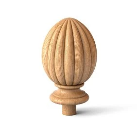
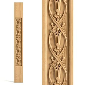
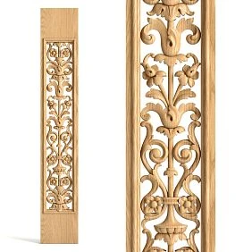
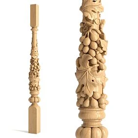
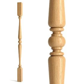

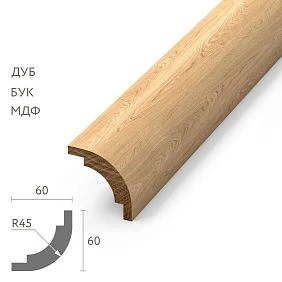
Blank, semi-finished product, and finished part are different starting conditions
First, clarify what work the supplier has already performed. The name "wooden blank" without a description of its condition is of little help to the process engineer: it can refer to completely different bases.
| What is received | What needs to be checked | Which operations may remain |
|---|---|---|
| Rough furniture blank | Actual geometry, condition of the wood, feasibility of achieving the finished size | Base preparation, shaping, drilling, sanding, finishing |
| Planed furniture blank | Flatness, straightness, relative position of surfaces | Part of project processing and preparation for finishing |
| Formed semi-finished product | Which dimensions are already final, and where rework is planned | Individual grooves, holes, trimming, or profile completion |
| Finished element without coating | Compliance with the drawing, assembly unit, and finishing system | Primarily finishing and installation; rework only after inspection |
Planning alone does not confirm that all surfaces are suitable for precise referencing. The absence of paint also does not mean that the part is intended for re-milling.
A detailed comparison of readiness levels is covered in the article “Solid wood furniture blanks: rough, planed, or ready for finishing — what to choose”. The next step is more important here: how to organize the remaining processing of the selected base.




First, describe the finished part
The sketch must show the final overall dimensions, holes, slots, contact surfaces, and areas that will remain exposed after assembly. For a ready catalog model, use STAVROS product drawings, checking the document against the selected article number and size variant.
Do not limit yourself to a general rectangle. For a leg, the top section for mounting is important; for a handle, the location of the mounting points and the grip shape; for an overlay, the contact plane. Conditionally identical dimensions do not yet make parts interchangeable.
Separate dimensions into final and intermediate. If the length after trimming should be 200 mm, the original 220 mm cannot be used as the final dimension when marking the mounting without recalculation. For each critical dimension, specify the permissible deviation according to the project and the verification method. The wording "approximately in the center" is insufficient for a repeating series.
The finishing system is also part of the input data. A fit calculated for bare wood may change after coating. Determine in advance which surfaces will be painted and which must remain free of finishing materials. For dimensions sensitive to coating, specify the control stage: after machining or after finishing. Otherwise, two craftsmen may obtain different measurement results, each formally following the same note on the drawing.
Our factory also produces:

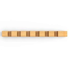
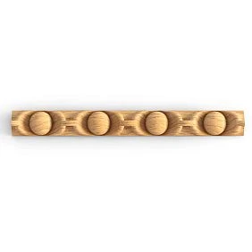
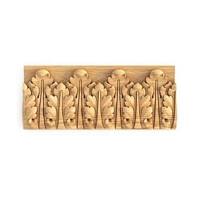
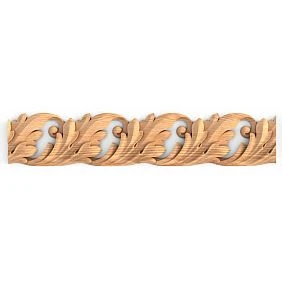
Which dimensions are truly critical
A critical dimension affects assembly, function, or the recognizable shape of the part. It is not necessarily the largest. A small offset of a hole is sometimes more important than a deviation in a decorative area.
| Detail | Dimensions and areas for mandatory inspection |
|---|---|
| Furniture leg | Mounting height, top section, maximum and minimum profile diameters, mounting position |
| Wooden handle | Center distance, fastening zones, overall dimensions, thickness and grip accessibility |
| Carved overlay | Contour, maximum protrusion, base thickness, mating plane |
| Profile part | Cross-section, position of mating sections, length after trimming |
| Modular post | Axis, length between mounting surfaces, fitting diameters and depths |
For a finished element, the letter designations of dimensions are read from the specific drawing. You cannot automatically assume that the letter C means the same parameter for any product group.
In the inspection card, it is useful to separate two checks: "the part matches its own drawing" and "the part fits the mating furniture assembly." The first does not replace the second: the error may be in the joint design itself.
Get Consultation
Incoming inspection: find the material from which the part will be made
Inspect the ends, longitudinal surfaces, edges and, if the blank is glued, the accessible glue joints. Note cracks, chips, knots, open seams and traces of foreign inclusions. Then compare them with the future contour and fixation zones.
A surface processing mark that will be removed during preparation and a crack at the location of the future neck are different cases. But a defect cannot be ignored merely because the area will later become waste: before removal, it may participate in clamping or rotate together with the blank. A questionable base is first removed from the working route and assessed separately.
Check the dimensions at several cross-sections. A single width measurement in the middle will not reveal tapering at the end. Using a ruler, a square, and suitable measuring tools, assess straightness, flatness, and the relative position of the sides. Strong clamping can temporarily straighten a part on the table, but this does not prove that it will retain its geometry once released.
Already at this stage it should be clear whether the required part can be obtained after creating the references and removing unusable areas. Wood blanks for furniture are assessed by the minimum usable size at the working area, not by the largest reading of the measuring tool. If the initial geometry is insufficient, the problem is solved by choosing a different base or by an agreed-upon change to the design.
Check the condition of the wood before precise operations
The geometry of solid wood is related to its moisture content and storage conditions. Wood exchanges moisture with the surrounding air; this relationship and the control of dimensional changes are described in the USDA Forest Service handbook. Therefore, an accurate measurement immediately after transfer from different conditions is not always sufficient to begin finish machining.
Compare the condition of the batch with the workshop conditions and the future use of the furniture. Monitor moisture with an instrument that has suitable settings and a methodology for the material. Generic “a day to acclimatize” or a single moisture percentage for all products do not replace the requirements of a specific production process.
Oak blanks for furniture and beech blanks require the same control discipline. The choice of species does not eliminate the need to check storage, geometry, and stability before operations after which the size can no longer be corrected.
Establish a reference face, edge, and end
A reference is a surface or geometric element from which the position of the part is set and dimensions are measured. For a rectangular base, it is convenient to separately designate the reference face, the guide edge, and the datum end. Before use, they are checked and, if necessary, created by machining.
Order matters. If you first drill holes from an uneven edge and then make it straight, the coordinates relative to the new edge will change. Therefore, the sequence must explain at which stage each datum appears and until which operation it is retained.
Let's consider a conditional part 200 mm long with two holes 128 mm apart. With a symmetrical arrangement, the centers are located 36 and 164 mm from the finished end face: (200 − 128) / 2 = 36 mm.
If 10 mm is to be removed from this end face of a 220 mm rough blank, the corresponding coordinates from the rough end face will be 46 and 174 mm. Marking 36 and 164 mm before trimming will shift both holes by 10 mm relative to the finished part. The center-to-center distance will remain correct. That is why you need to check both the distance between the holes and their reference to the datum.
When re-fixturing, maintain a clear reference system
After rotating or flipping the workpiece, it must be clear which side has become the locating surface and how the coordinates have been transferred. A simple mark on the face side helps avoid confusion, but precise work requires repeatable fixturing in a jig.
On a CNC machine, the physical locating and the program zero point are coordinated separately. The workpiece corner specified in the program must correspond to the actual setup, not to a convenient corner of the 3D model. In Autodesk documentation on configuring milling operations the model origin and the workpiece bounding box points are distinguished; tooling is also taken into account there.
A change in thickness, end face, or position of the part requires verifying the adopted reference. If the outer contour has already been milled and the previous edge is gone, the next operation cannot be performed "from the same edge" without verification. A new setup should be planned in advance.
When the program accounts for tooling, its model must include the clamps and stops actually in use. Verifying the toolpath against a conditional empty workpiece will not reveal a collision with a fixture that is absent from the model. Before running the first part, the digital setup is compared with the actual setup.
Where the face side will remain
Before processing, identify the surfaces that will be visible after assembly. On a handle, this may be the outer plane and the grip area; on a leg, several sides; on a post, the entire circular profile. Such a part does not always have a single hidden side where an unsuccessful section of texture can be placed.
Match the wood grain to the finished contour. On a rough surface it may look different than after a layer is removed. For a series, decide in advance how important the similarity of adjacent parts is: four legs under one cabinet and twenty independent decorative inserts place different demands on selection.
With a clear finish, color, texture, and the arrangement of the lamellae are taken into account. Under enamel, the requirements for the external pattern may be softer, but requirements for the integrity of the wood and joints remain. Paint hides color, not a structural defect.
Check grain direction together with shape
For an elongated furniture part, it is important how the grain runs through thin sections, transitions, and fastening zones. A beautiful pattern on a wide surface does not guarantee a successful arrangement of grain in a narrow bridge.
On a shaped handle, assess the future grip area; on a turned leg, the neck; on a carved overlay, the protruding leaves. A sharp change in grain direction or a short section across a thin part requires a separate assessment of the structure. Such a zone should not automatically be considered suitable merely because the overall thickness of the blank is sufficient.
Wood orientation is taken into account when planning processing and supporting edges. At the same time, grain direction does not replace the feed rules for a specific machine and tool. The route, method of fixation, and settings are coordinated with the equipment; a universal command to “follow the grain” for all operations is incorrect.
Create a map of the remaining operations
For each operation, write down four things: what to achieve, from what to set the part, by what to hold it, and with what to check the result. Then the route will become suitable for work, rather than remaining a list of machine names.
Below is a conditional route for a small profile part. It assumes that the selected tooling allows drilling to be performed before the final formation of the outer contour.
| Stage | Task | What to check before moving on |
|---|---|---|
| Acceptance | Confirm the suitability of the base | Material, condition, actual dimensions |
| Preparation of bases | Create a reference plane and guide edge | Geometry and stable setup |
| Calibration and trimming | Obtain the specified dimensions and reference end | Thickness, width, length, remaining material |
| Drilling | Drill the mounting holes | Coordinates, diameter and depth |
| Contour forming | Obtain the profile without losing the mounting zones | Shape, residual cross-sections, edge condition |
| Sanding and test fitting | Prepare the surface and check the assembly | Fit, appearance, critical dimensions |
| Finishing | Apply the agreed coating system | Color, gloss and integrity of the fits |
For another part, the order may change. For example, drilling after profiling will require suitable support tooling. It is important to justify the sequence and verify it on the first part, rather than declaring one route universal.
Turning blank: check the axis and clamping zones
For longitudinal turning, the future profile must be positioned relative to the axis so that there is enough material along the entire length. Measure the usable cross-section, mark the maximum diameter, the finished length, and the areas for the chosen mounting.
A nominal rectangle of 72 × 68 mm does not allow obtaining a full circle with a diameter of 70 mm: the limitation is set by the smaller side. Even a diameter of 68 mm here is only a geometric limit, without taking into account deviations and material removed during machining. First, the actual usable area is assessed, then the profile is assigned.
Cracks, foreign inclusions, and unreliable areas in the mounting are checked before installation. Recommendations from the Canadian Centre for Occupational Health and Safety for wood lathes directly provide for the use of blanks without dangerous defects and for checking the mounting. The possibility of subsequently grinding away damage does not make the initial setup suitable.
If the required turned elements for furniture already exist, compare your own route with the section ready-made turned wooden elements. For an assembled module, the fits and joints are also checked: a finished profile does not yet mean a finished furniture assembly.
Routing blank: account for the remaining material
Compare not only the original thickness and the depth of a single groove. What matters is the material that will remain after all intersecting cutouts, holes, and subsequent sanding.
In a hypothetical 24 mm thick part, cutouts 8 mm and 6 mm deep on opposite sides leave 10 mm between them where they are located opposite each other. This is a geometric calculation: 24 − 8 − 6 = 10 mm, before any additional material removal from these surfaces. It does not confirm sufficient strength. Strength is assessed taking into account the shape, grain, purpose, and load.
Check tool access. The cutter must form the required area without colliding with the clamp or an adjacent part of the workpiece. The clamp itself must hold the blank even after material removal. If the outer contour separates the product from the base, the method of holding it during the final stage must be planned before work begins.
For a formed semi-finished product, it is especially important to know the thickness of the base under the relief. The maximum protrusion of a decorative part does not show how deep a cutout can be made from the reverse side.
Drilling blank: position matters more than a pencil mark
For a hole, specify the diameter, axis direction, coordinates from datums, depth, and entry side. For a blind hole, clarify what exactly the depth means: the length of the full-diameter section or the distance to the deepest point of the tool. This affects the remaining thickness of the wood.
Separate the holes in the wooden element from those in the mating furniture part. A handle may have a prepared mounting, while the face panel is what needs drilling. A support may already have a connector installed. Re-machining "using a common template" in these cases can ruin a finished assembly.
The distance to the edge and the hole dimensions are chosen based on the specific fastener, material, and construction. There is no single universal offset for any dowel screw, threaded insert, or screw. On a test piece, check both the hole itself and the fit of the intended fastener.
For through drilling, decide in advance how to support the exit side and hold the workpiece. After the operation, assess not only the center of the hole but also the condition of the edges on both sides.
The first part checks the entire route
Before making twenty identical elements, run one blank through all the remaining operations. Checking only after milling will not show that during assembly a screw hits the bottom of the hole or the finished profile interferes with the grip.
On the trial part, check the dimensions, fits, assembly, appearance, and the chosen finish. The geometry of the finished product is also assessed after release from the fixture: the clamp should not mask deformation. If you changed the base, the fastener, or the sequence, update the process sheet before starting the batch. Keep the approved sample together with the measurement results.
A good first part confirms the route for the verified conditions, but it does not cancel series inspection. After a tool change, readjustment, or the appearance of a deviation, repeat checks are needed. Their scope is determined by which dimension may change and how this will affect assembly.
It is convenient to mark three outcomes: “suitable,” “needs rework,” and “do not allow into the series.” The last option is also useful: an unsuitable base is detected before the work of the entire batch has been invested in it.
When a finished element reduces processing
Wooden furniture blanks and semi-finished products are compared by the cost of the part at the same stage of readiness. The price of the initial base is only part of the costs. Added to it are equipment preparation, the program, tooling, trial passes, shaping, sanding, and inspection.
For in-house manufacturing, it is convenient to calculate the costs of the batch and divide them by the number of accepted good parts. This way, both setup and losses from defects remain in the calculation. For a purchased element, take into account procurement, delivery, incoming inspection, and the truly necessary rework. Common finishing operations are included in both options on comparable terms.
For a small series, preparing a complex relief may take more resources than making it directly. For a steady, large, repeating order with its own tooling, the comparison result may be different. A finished part is advantageous when it suits the project and removes real operations from the route.
Legs: check the finished geometry before starting your own processing
Blanks for furniture legs are evaluated by height, upper mounting part, and future profile. For a simple shape, in-house processing may be convenient, but it should still be compared with a ready-made option by batch cost.
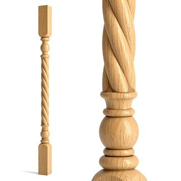
In the section unpainted furniture legs different types can be compared. geometric furniture legs allow checking the option with already formed edges. Turned furniture legs — a ready-made turning profile. carved furniture legs help assess whether relief manufacturing can be excluded.
Compare the specific model with the furniture drawing. Trimming a ready-made leg may change the lower section or remove part of the mounting area. If a different size is required, first determine the permissible solution, and then plan the modification.
Handles, overlays, and moldings: which operations can be excluded
Instead of forming the grip yourself, you can choose unpainted furniture handles. For example, in the product card handles HL-011 different dimensional versions are specified, including A × B × C × D = 180 × 40 × 25 × 128 mm. The product is supplied without a finish; the fastening kit is included in the price. This is a reason to check the finished component instead of making it from a block; compatibility with the facade is determined separately according to the drawing and fitting.
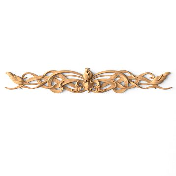
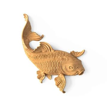
For a decorative facade, compare milling the relief directly in the panel and installing carved inlay for furniture. In the second case, the relief is already made, but requirements arise for the joint, projection and connection to the base. These solutions are not always interchangeable. Other formed elements can be compared in the section wooden carved decoration.
If a repeating profile is needed, Wooden trim allows you to consider the route from cutting, joining, finishing and installation. Check the material of the specific item: the general assortment includes different bases. The cross-section size and length for cutting are taken from the selected version.
Finishing requires separate control
After machining, check for tool marks, fuzz, edges and grip surfaces. Sanding should not imperceptibly change the fitting dimensions or round the edges needed for a tight joint. The finish surface is assessed together with the geometry, not instead of it.
For purchased parts, clarify the condition of the blank and the quality of processing. In the description quality of wooden products STAVROS separately considers regluing “for enamel” and “for tinting,” as well as the quality of sanding. These characteristics answer different questions: the external selection of wood and surface preparation are not the same parameter.
Useful for a preliminary comparison Product samplesbut the final test is carried out on the material and profile corresponding to the project. Mounting and finishing materials is selected as a compatible system. After the coating dries, the fits and joints are rechecked if the finish could have affected them.
What to record in the blank specification
The entry "wooden blank — 12 pieces" does not tell the craftsman what they will receive or what they must do. Link the procurement item to a specific part and its routing.
| Field | What to specify |
|---|---|
| Part number | Designation on the furniture drawing |
| Source item | Supplier's article number or an agreed description of the base |
| Material | Species, blank finish, requirements for visible wood |
| Initial dimensions | Length, width, thickness or cross-section with permissible deviations |
| Finished dimensions | Overall dimensions and critical parameters per drawing |
| Bases | Reference plane, guide edge, end face or axis |
| Remaining operations | Sequence with reference to the process chart |
| Fastening and finishing | Specific assembly and approved coating system |
| Quantity | Requirement for usable parts; trial and spare items separately |
| Control | Inspected dimensions, measurement methods, sample status |
If ready-made geometry is used, do not leave old operations in the routing just because they were intended for the rough blank. Remove unnecessary turning or profiling, refine the setup, and keep the link to the card of the selected product.
Questions before starting a batch
Can a planed side be considered a finished base?
After checking its geometry and suitability for the selected setup. The name of the treatment alone does not confirm flatness, straightness, or the required angle between surfaces.
What should be done if the dimensions are sufficient but the part is inconvenient to secure?
Review the tooling, routing, or the base itself before machining. Overall dimensional suitability and the ability to set up stably are different conditions. You cannot count on reliably holding a part left without support with a random clamp.
Should the trial be repeated for a finished unpainted element?
Yes, if this is the first setup of the model in this project. The shape has already been made by the supplier, but the compatibility of the fastening, fits, and finish with your furniture still needs to be confirmed.
Can the routing be transferred to another size of the same model?
Only after checking the differences. Another version may have a different cross-section, fastening zones, and fixation conditions. A matching model name does not replace comparing the drawings.
Where to buy wooden blanks and ready-made furniture components
Before buying wooden blanks for furniture, prepare a description of the finished part and a map of the remaining operations. For the rough base, you will need agreed dimensions and material condition. For a formed element — a specific item code, a drawing, and confirmation of which operations the workshop actually needs.
In the STAVROS catalog, start with wooden furniture components: check whether there is a suitable leg, handle, turned module, overlay, or profile with the geometry already completed. The catalog of ready-made products should not be perceived as a list of universal bars for any processing. Choose the material and finish in the specific product card.
For repeat orders, review conditions for manufacturers and provide the supplier with an agreed specification. It should clearly state the finished result, quantity, surface requirements, and the processing that the workshop retains. Then incoming inspection can be carried out using measurable criteria, and a base with an already verified route can be sent into production.