Article Contents:
- What the BL-001 false beam is
- Outer dimensions and usable internal space are not the same thing
- Why a 70 mm pipe does not yet mean that the BL-001 is suitable
- First measure what needs to fit inside
- Why a photo of the ceiling does not replace a dimensioned detail drawing
- The mounting also takes up internal space
- It is better to calculate usable space after choosing the mounting
- What can be concealed inside a decorative false beam
- The false beam must not block access to serviceable components
- What to check on the ceiling before ordering
- The false beam and built-in lighting should be designed together
- The false beam and ventilation also require a shared ceiling plan
- Construction materials should be coordinated by assembly, not by photograph
- MDF and MDF with oak veneer solve different finishing tasks
- When the finish needs to be determined
- Why a sample is especially useful for the veneered option
- Construction products should be checked at the real scale of the room
- A single false beam and a rhythm of several beams are different projects
- Beam spacing must be checked together with engineering intersections
- The length of BL-001 is 2750 mm: this means joints must be planned in advance
- Where it is best to place a visible joint
- A symmetrical cutting layout sometimes looks better than one with minimal waste
- The quantity must be calculated in whole products
- A cutting map is more important than a simple sum of meters
- Offcuts from cutting can have a useful function
- Building materials for the home are best coordinated before the final ceiling finish
- The topic applies not only to a private house
- A faux beam should be included in the general list of finishing materials
- Bulk building material: one approved standard is needed for a series of rooms
- A control section is useful for a large project
- When BL-001 is better not used for concealing utilities
- Minimum data package before requesting from the supplier
- Several utilities inside should be counted as a single overall dimension
- A route turn is more complex than a straight section
- The most inconvenient section determines the suitability of the entire scheme
- An uneven ceiling reduces the actual installation clearance
- The end face of the false beam must be designed in advance
- A wall junction requires checking the wall geometry
- A corner made of two false beams should be built as a separate assembly
- The veneered series requires controlling the direction of the grain
- Joints and cutting should be checked at the same time
- How to calculate a series of five parallel beams
- Why you cannot add up all the meters of an object into a single figure
- Transportation of the 2750 mm length also needs to be taken into account
- The storage location should protect the finished surface and geometry
- A control section is especially useful with a tight internal cavity
- When it is better to choose a false beam of a larger cross-section or another solution
- The category is best reviewed after the required dimensions are clear
- What to check right before payment
- The BL-001 false beam should conceal utilities, not create new problems
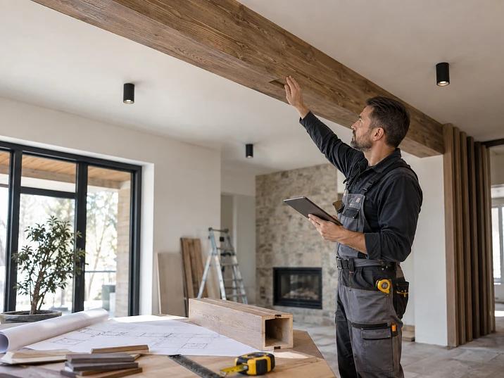
A false beam is often chosen by its outer dimensions: if the decorative box has a cross-section of 100 × 100 mm, it seems that a pipe or cable run about 70 mm in diameter will fit inside without any problems. But this approach is dangerous. Inside, you need to account for the wall thickness, the mounting base, fasteners, ceiling unevenness, utility crossings, and the technological clearance required for actual installation.
Therefore, when choosing materials for construction, you first need to measure not the decorative beam, but everything that must fit inside it. After that, a dimensional assembly is built, the actual free cavity is checked, the BL-001 version is selected, whole products are calculated, and only then is the order placed.
For the BL-001 false beam, the following sequence is especially useful:
measurement of utilities → dimensional assembly → verification of the internal cavity → installation zone → version selection → cutting → joints → finishing → order → control installation.
This way, the decorative beam truly conceals engineering elements rather than creating a new conflict on the finished ceiling.
What the BL-001 false beam is
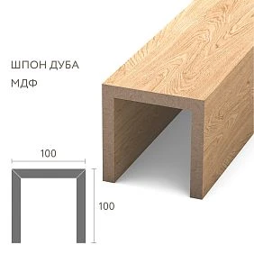
False Beam BL-001 — A U-shaped decorative false beam. According to current STAVROS data, the outer cross-section of the product is 100 × 100 mm, the wall thickness is 13 mm, and the length is 2750 mm. Versions are available in MDF and in MDF with oak veneer.
The U-shaped form creates an internal cavity. This is precisely what allows the beam to be considered not only as a decorative ceiling element, but also as a shell inside which, with a properly designed assembly, utilities can run or individual fastening elements can be located.
At the same time, the false beam remains an interior decorative product. It should not be perceived as a load-bearing structural beam and does not replace the designed elements of a floor slab or frame.




Outer dimensions and usable internal space are not the same thing
The external 100 × 100 mm cannot be used directly as the permissible dimensions of the concealed route.
Based on the U-shaped geometry and a uniform wall thickness of 13 mm, the approximate internal width between the side walls is:
100 − 13 − 13 = 74 mm.
Approximate internal height from the inner surface of the top wall to the open side:
100 − 13 = 87 mm.
This is a geometric estimate, not a ready installation tolerance. The actual usable space will be smaller if there is a block, strip, bracket, cable holder, or other mounting element inside.
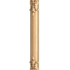
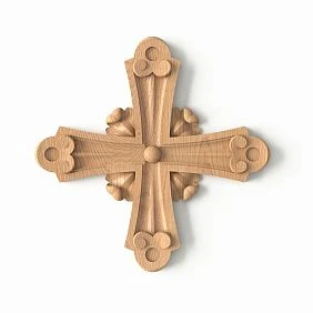
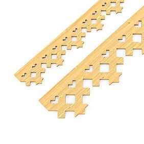
Our factory also produces:

Why a 70 mm diameter pipe does not yet mean that BL-001 is suitable
Let's assume the outer diameter of the pipe is 70 mm. The internal width based on simple geometry is about 74 mm. On paper, only about 2 mm remains on each side.
Such a margin practically does not allow compensating for:
- pipe deviation from the axis;
- clamps;
- ceiling unevenness;
- mounting fasteners;
- actual manufacturing and construction tolerances;
- the need to physically put on or install the beam.
Therefore, the comparison "70 is less than 100" is incorrect, and the comparison "70 is less than the approximate 74" still does not give permission for installation. A complete assembly is needed.
Get Consultation
First, measure what should end up inside
| Element | What to measure |
|---|---|
| Pipe | Maximum outer dimension including the mount |
| Corrugation | Actual outer diameter and bend locations |
| Cable duct | Width, height, lid and connectors |
| Fastening | Offset from the ceiling and width of the installation zone |
| Base | Variations and deviations |
| Installation gap | Minimum clearance for installation |
You need to measure the maximum, not the average value. The route may have one enlarged section, and that will determine the suitability of the entire layout.
Why a photo of the ceiling does not replace a dimensional detail
A photo shows that a pipe or cable runs through the area. But it rarely gives a precise understanding of:
- indentation from the ceiling;
- offset from the wall;
- maximum diameter;
- size of the clamps;
- point of intersection with another route;
- base level difference;
- space for installing the beam itself.
Even a simple hand-drawn dimensional sketch is enough to place an order, as long as it contains all the critical dimensions. A beautiful drawing is not required; unambiguous dimensions are mandatory.
The mounting also takes up internal space
A common mistake is to account only for the utility line.
The following may additionally be located inside:
- wooden mounting block;
- mounting bar;
- bracket;
- fastening plate;
- cable holders;
- fastener heads.
The chosen fastening method depends on the base and the project, so a universal mounting scheme cannot be specified for all ceilings. However, space for the fastening must be reserved before purchasing the false beam.
It is better to calculate the usable space after choosing the fastening
For example, the internal width by geometry is about 74 mm, and the mounting bar occupies 15 mm of the usable area on one side.
Then the free space in this plane can no longer be estimated as 74 mm. The actual scheme must take into account the position of the bar and the utilities relative to each other.
Therefore, the sequence "first buy the beam, then figure out the fastening" is especially risky for a tight assembly.
What can be hidden inside a decorative faux beam
The U-shaped internal cavity allows for design consideration of placement:
- electrical cables;
- cable runs;
- corrugated conduit of suitable dimensions;
- small pipes when sufficient free space is available;
- individual existing structural elements that need to be visually concealed.
But the ability to conceal a specific utility is determined not by the product name, but by the dimensional assembly.
The faux beam must not block access to serviceable components
Before ordering, check whether there are any elements inside the area that will require access after the finishing is completed.
For example:
- connections;
- inspection points;
- connectors;
- power supplies;
- valves;
- serviceable fasteners.
If access is needed, the design must provide a means of servicing. It cannot be assumed that a decorative shell will permanently cover any engineering element without consequences.
What to check on the ceiling before ordering
Before placing an order, it is useful to go along the entire line of the future beam and check:
- ceiling level;
- local height differences;
- corners;
- height change;
- position of utilities;
- route turns;
- beam exit to the wall;
- junction with the cornice;
- lighting fixtures;
- ventilation grilles;
- floor-to-ceiling wardrobes;
- door and window reveals, if they are nearby.
One conflict at the end of the line can force the entire composition to be reconsidered.
The false beam and built-in light must be designed together
If track lights, spotlights, LED strips, or power supplies are planned nearby, their positions must be coordinated before ordering the beam.
Problems arise when, after marking out, it turns out that the decorative beam:
- blocks a light fixture;
- interferes with a mounting hole;
- blocks access to the power supply;
- creates an unwanted shadow;
- conflicts with the track along the axis.
Fixing this after the final finishing is much more difficult than shifting the axis in advance.
A false beam and ventilation also require a shared ceiling plan
Checked:
- grilles;
- diffusers;
- air ducts;
- inspection hatches;
- service points.
A false beam should not be designed as a separate decorative line on top of an already finished engineering ceiling.
Construction materials must be coordinated by assembly, not by photograph
Construction materials become part of the project only at the intersection of two data groups.
Product data:
- article number;
- outer section;
- thickness;
- length;
- the material;
- finish option.
Project data:
- track size;
- position on the ceiling;
- mounting;
- joints;
- service areas;
- finish;
- quantity.
Only after combining these two sets can we speak of a correct order.
MDF and oak-veneered MDF solve different finishing tasks
BL-001 is available in two versions.
MDF is suitable for projects where the surface is intended to be covered with a covering finish and the natural wood texture is not part of the visual solution.
Oak-veneered MDF is chosen when the wood texture is important to the project and appropriate finishing options are provided.
Geometry and finish cannot be chosen independently of each other: a prominent ceiling composition is perceived simultaneously as form and surface.
When the finish needs to be determined
Not after on-site installation, but before purchase.
You need to understand:
- whether a covering finish will be applied;
- whether a visible wood grain is needed;
- whether tinting is planned;
- what the beam should match — the doors, furniture, baseboard, or ceiling;
- whether the finish should be the same across the entire beam series.
If the decision is made after installation, there is a risk of incompatible surface preparation and mismatched color.
Why a sample is especially useful for the veneered option
Natural veneer has natural variation in its pattern.
For a prominent ceiling composition, it is useful to assess in advance:
- the texture;
- trial finish;
- degree of darkening after tinting;
- combination with furniture and doors;
- overall perception at ceiling height.
At the same time, the natural pattern of different elements does not have to be absolutely identical.
Building products need to be checked at the real scale of the room
Building products on a product card are always perceived outside the context of the room. A 100 × 100 mm cross-section may seem massive on the screen, but in a room four meters high it looks much calmer.
For a faux beam, it is useful to check:
- ceiling height;
- the width of the room;
- the number of beams;
- spacing;
- direction of lines;
- distance to walls;
- combination with furniture and lighting.
One false beam and a rhythm of several beams are different projects
If the ceiling contains five parallel beams, an error in the spacing of 40–50 mm visually accumulates across the entire composition.
Therefore, it is better to set axes:
axis 1
axis 2
axis 3
and tie them to the room's dimension grid, rather than placing them "approximately every meter."
The beam spacing must be checked together with engineering intersections
An ideal decorative rhythm may conflict with the actual ventilation route or light fixtures.
If one axis is shifted due to engineering, the entire composition needs to be evaluated as a whole: sometimes it is better to slightly change the overall spacing than to leave one obviously misaligned beam.
The length of BL-001 is 2750 mm: this means joints must be planned in advance
If the visible line is longer than one product, a joint appears.
For example, a room is 5.8 m long. Two products of 2750 mm each give:
2750 + 2750 = 5500 mm.
remains:
5800 − 5500 = 300 mm.
Simply adding a short 300 mm fragment in a random place is a poor design decision. The location of the joints must be determined in advance.
Where it is best to place a visible joint
There is no universal point, but the joint can be tied to:
- a cross beam;
- architectural axis;
- boundary of the functional zone;
- to another intended element of the composition.
The goal is to make the joint part of the design, not a random result of the product length.
A symmetrical cut sometimes looks better than a minimal-waste one
For a 5.8 m line, you can try to get three segments with visually more balanced joints instead of one short leftover at the edge.
This solution may increase material consumption but improve the appearance. Therefore, optimizing only for minimal waste is not always right for a prominent ceiling composition.
The quantity should be calculated in whole products
Let's assume the total length of the decorative lines is 8.0 m.
The length of one BL-001 is 2.75 m.
Arithmetic minimum:
8,0 / 2,75 = 2,91.
This means you cannot order fewer than three items.
But the actual cutting plan may require four if individual segments cannot be rationally obtained from three planks, taking into account the location of joints.
The cutting plan matters more than the simple sum of meters
First, it is useful to list all the required segments.
For example:
| Zone | Required length |
|---|---|
| Line 1 | 2600 мм |
| Line 2 | 1900 мм |
| Line 3 | 900 мм |
| Line 4 | 700 мм |
After that, the segments are distributed among the 2750 mm items. This shows which leftovers can actually be used further.
The leftover from cutting can serve a useful purpose
The remaining 900 mm piece is not necessarily waste.
It can be used:
- on a short section;
- as a sample;
- for a control finish;
- for a small repair reserve;
- in another project node.
Therefore, it is better to calculate the cutting layout for the entire project at once.
Building materials for the home are best coordinated before the final ceiling finish
Building materials for the home related to ceiling utilities are especially sensitive to late changes.
If BL-001 appears in the project after the ceiling is completed, adjustments may be required:
- electricians;
- lighting;
- painting;
- built-in furniture;
- curtain units;
- ventilation.
Therefore, the dimensional unit is best coordinated before the final release of the finish.
This topic applies not only to a private house
A false beam can be used in:
- a restaurant;
- a hotel;
- Office;
- an office;
- a public interior;
- apartment;
- country house.
The scale of the project changes, but the logic for checking the interior space remains the same.
The false beam must be included in the general list of finishing materials
Materials for finishing work must be described specifically.
A good line:
BL-001 / MDF with oak veneer / 100 × 100 × 13 × 2750 mm / quantity / finish / zone
Weak line:
ceiling beams — 8 pcs.
The second entry does not allow verification of either the correctness of the product or the execution.
Building material in bulk: a single approved standard is needed for a series of rooms
If construction material wholesale is purchased for a network of rooms, one SKU is not enough.
It is necessary to record:
- BL-001;
- material option;
- finish;
- the mounting assembly;
- spacing;
- the axes;
- joint logic;
- rules for routing around utilities.
This way, identical rooms do not gradually start to differ from one another due to installers' local decisions.
For a large project, a control section is useful
It is not necessary to assemble an entire room.
On a single fragment, you can check:
- the actual scale of BL-001;
- fit onto the selected mounting;
- the actual clearance around the utility;
- junction to the ceiling;
- visible joint;
- the selected finish.
After successful verification, the solution can be scaled to a series.
When BL-001 is better not used to conceal utilities
A false beam is not automatically suitable for any route.
It is better to consider another solution if:
- the actual dimensions of the utilities are close to the internal limit without installation clearance;
- there is a serviceable unit inside without access;
- the trajectory frequently changes direction;
- the fastening takes up most of the cavity;
- the beam conflicts with lighting or ventilation;
- the ceiling does not allow the selected assembly to be reliably implemented;
- the decorative scale does not suit the room.
An expert choice sometimes means rejecting a product in a specific area.
Minimum data package before requesting from the supplier
- Exact SKU BL-001.
- Selected material finish.
- Number of whole items.
- Layout plan.
- Lengths of all zones.
- Finish requirements, if already agreed.
- Project duration.
- Special packaging or delivery requirements, if critical.
If the task involves concealing utilities, a dimensional detail is additionally saved in the project documentation.
Multiple utilities inside must be counted as a single overall dimension
If two cable channels or a pipe together with corrugated conduit run inside, each element cannot be checked separately.
It is necessary to determine the overall rectangle actually occupied by all utilities, taking into account the distance between them and protruding fasteners.
For example:
- pipe — 32 mm;
- corrugated conduit — 20 mm;
- an actual gap is required between them;
- a clamp protrudes on one side.
As a result, the total width may turn out to be significantly greater than the simple sum of 32 + 20 mm. It is the maximum combined overall dimension that is compared with the usable internal space.
A turn in the route is more complex than a straight section
On a straight line, the communication can fit freely inside the beam, but at a turn it may extend beyond the allowable cavity.
This is especially important for:
- corrugated conduits with a bend radius;
- pipe elbows;
- cable channels with corner connectors;
- intersections of two routes;
- points where the cable enters through the ceiling.
Therefore, it is necessary to check not only the typical cross-section, but also the largest local section of the entire line.
The most inconvenient section determines the suitability of the entire scheme
If a 4.5 m track has a profile of 45 mm, and one clamp protrudes to 78 mm, it is this clamp that can make installation impossible.
A convenient technique is to run along the future beam axis and mark:
maximum width profile + maximum height profile + the location of this maximum.
This is more useful than the average size of the utility run.
An uneven ceiling reduces the actual installation clearance
On the drawing, the ceiling looks like a straight line. On site, there may be local variations.
If the internal cavity is designed with almost no clearance, even a small protrusion of the base can prevent installation.
Therefore, before ordering a long run, it is useful to check the ceiling along the entire axis, not just at one point.
Pay especially close attention when measuring:
- the start and end of the line;
- joint locations;
- areas near walls;
- points where utilities intersect;
- areas after plastering or ceiling work.
The end of a false beam must be planned in advance
Not every decorative line ends at a wall. Sometimes the end remains visible.
Before ordering, it is necessary to determine:
- whether the end is closed by a wall;
- whether the beam goes into a niche;
- whether it joins another beam;
- whether it remains exposed in the interior;
- whether a separate piece is needed for a neat finish.
If an open end is discovered only after installation, a decorative solution has to be devised on the already finished ceiling.
The wall junction requires checking the wall geometry
Even a squarely cut end can leave a noticeable gap if the wall deviates from vertical or has a local wave.
Therefore, for a prominent junction it is useful to decide in advance:
- whether the end will be fitted on site;
- whether there is a decorative element that covers the junction;
- whether a visible shadow gap is acceptable;
- whether a length allowance is needed for trimming.
Such decisions affect the cutting plan and the number of whole products.
A corner made of two false beams should be built as a separate assembly
If the lines meet at an angle, simple alignment of the axes is not enough.
Need to check:
- outer contour;
- inner cavity;
- mounting position;
- routing of utilities through the corner;
- visibility of the joint from below;
- direction of the finish.
If a pipe or cable also runs inside, the corner assembly becomes both decorative and functional.
The veneered series requires control of the grain direction
For MDF with oak veneer, not only the tinting matters, but also the overall logic of the visual direction.
On a long ceiling line, it is useful to decide in advance how the pattern is perceived on adjacent sections and joints.
Natural veneer should not be expected to be absolutely identical in pattern, but a random difference in direction can make the joint more noticeable.
Joints and cutting must be checked simultaneously
The most economical cutting may place a joint in the worst visual spot.
And conversely, perfect symmetry may require an additional whole piece.
Therefore, for each long line it is convenient to compare at least two options:
| Option | Advantage | Drawback |
|---|---|---|
| Minimum waste | Less material | The joint may end up random |
| Architectural joint | Better composition | More material may be required |
The choice depends on ceiling visibility and the project budget.
How to calculate a series of five parallel beams
Let's assume each line is 5.4 m long.
total net length:
5 × 5.4 = 27 m.
If you divide only the total length by 2.75 m:
27 / 2,75 = 9,82.
It seems that 10 units are enough.
But each 5.4 m line by itself requires a minimum of two units. Five independent lines require a minimum of:
5 × 2 = 10 units.
And this is still without taking into account the chosen joint locations. If the project requires symmetrical cutting, the actual quantity may be greater.
Why you cannot add up all the meters of an object into a single figure
The total meterage is useful for a preliminary estimate, but the final order is determined by the set of specific segments.
For example, 11 m could consist of:
- one 11 m line;
- four lines of 2.75 m each;
- ten short sections.
With the same total meterage, the cutting plan and offcuts will differ.
Transportation of the 2750 mm length also needs to be taken into account
Before ordering, it is worth checking how the items will fit:
- in transport;
- in the elevator;
- to the staircase;
- into the room;
- to the temporary storage location.
If the object has difficult access, it is better to check the logistics route before delivery, not after the arrival of long-length goods.
The storage location must protect the finished finish and geometry
A beam should not be perceived as a short box that can be placed in any corner.
For a series with a length of 2750 mm, it is necessary to allocate space in advance where the products will not interfere with other work and will not be subjected to accidental load.
If the finish has already been completed, it is additionally important to exclude damage to visible surfaces when moving around the object.
The control section is especially useful in a tight internal cavity
If the communication occupies a significant part of the available space, a theoretical drawing is not enough.
A single test fragment allows you to check:
- whether the beam can physically be fitted onto the assembly;
- whether it catches on the mounting;
- whether the installation gap is sufficient;
- how noticeable the ceiling deviations are;
- whether the product can be removed if maintenance is needed.
For a large series, such a check is significantly cheaper than reworking an already ordered volume.
When it is better to choose a larger-section false beam or another solution
If the actual route fits only "just barely," BL-001 should not be chosen solely because the 100 × 100 mm section is visually appealing.
It is more practical to consider another size or another concealment method if:
- no space for mounting;
- no installation clearance;
- the corner section does not fit;
- constant access to utilities is required;
- the line becomes excessively fragmented due to joints.
The choice of a decorative element must be governed by the actual assembly.
It is better to review the category after the required dimensions are clear
If, after measurements, BL-001 does not fit in terms of interior space or scale, it makes sense to compare other wooden faux beams, rather than trying to adapt the chosen model at any cost.
That is, the catalog is used after the task is defined: first the assembly and dimensions, then the product.
What to check right before payment
- the order specifies exactly BL-001;
- the required material version is selected;
- the outer dimension matches the project;
- the inner cavity has been checked against the actual assembly;
- the fastening is taken into account;
- inspection points are not blocked;
- the quantity is calculated in whole units;
- the cutting is checked;
- the joints are designed;
- the finish is agreed upon;
- the current version of the specification is used.
The BL-001 false beam should conceal utilities, not create new problems
The correct sequence is simple:
- measure the utility run;
- measure the fasteners and the base;
- draw the dimensioned assembly detail;
- check the usable internal cavity;
- assess access to serviceable elements;
- coordinate the position with lighting and ventilation;
- choose the BL-001 version;
- set the axes and joints;
- create a cutting map;
- approve the finish;
- order the full quantity of products;
- on a large project, check a control section;
- only after that, scale the solution.
The BL-001 false beam is a good example of why an interior building material cannot be chosen based only on a photo and external dimensions. For a real project, the entire system matters: the internal cavity, utilities, installation, ceiling, light, ventilation, cutting, and finish.
If these parameters are checked in advance, the U-shaped false beam becomes a clear tool for decorative design and masking engineering elements. But if you focus only on the external 100 × 100 mm, the installation problem will be discovered only after purchase.