















Article Contents:
- Wooden cornice KZ-005 110×40/41 mm: what sizes are actually available
- LED profile 100 mm from the ceiling and KZ-005 with a height of 110 mm: where the conflict arises
- What three LED profile dimensions are needed before ordering a wooden cornice
- Wooden ceiling plinth and ready-made lighting: what should be adjusted first
- Why you cannot block the KZ-005 diffuser without checking the light output
- Wooden cornice KZ-005 as a screen for hidden lighting: when geometry works in your favor
- When 40–41 mm of KZ-005 offset is not enough to hide the LED from direct view
- When it is better to choose a lower profile instead of KZ-005
- Same wall and oak KZ-005 with a length of 2400 mm
- Where to place the KZ-005 joint relative to the light line
- Cornice KZ-005 and hidden wiring: what to check before drilling
- LED profile is not parallel to the ceiling: why the 100 mm size needs to be checked along the entire wall
- LED driver: why it cannot be locked behind a wooden cornice without access
- Example of a full room with LED gap
- Where to place the longitudinal joint relative to the LED
- What to do if KZ-005 overlaps the LED by only 10 mm and the light looks normal
- If the LED backlight is directed down the wall
- KZ-005 from MDF 2600 mm: when 200 mm of extra length actually saves the plank
- How to calculate the KZ-005 reserve without mechanical 10%
- Revision not only of the driver: what else should remain accessible
- Final procurement specification for KZ-005

The aluminum LED profile is already built into the wall, the backlight line is routed and working. After that, KZ-005 was chosen for the upper part of the interior — a tall wooden cornice 110×40/41 mm. On the plan, the LED line is 100 mm from the ceiling. If we take these two numbers literally, we get:
110 − 100 = 10 mm.
That is, KZ-005 nominally overlaps the existing light line by 10 mm.
But this calculation does not yet answer the main question. To decide whether the cornice can be purchased, you need to understand to which point of the LED profile the 100 mm is measured. If to the top edge of the aluminum profile — the conflict indeed starts immediately. If to the axis — the actual overlap depends on the height of the profile itself. If to the bottom edge — KZ-005 may cover an even larger part of the lighting system.
The second layer of the task is light. Even if it is decoratively acceptable to cover part of the aluminum profile, you need to check:
-
whether the diffuser remains open;
-
whether the lower edge of KZ-005 falls into the light beam;
-
whether the diffuser and the strip can be removed;
-
whether the power supply is accessible;
-
whether a sharp shadow appears;
-
doesn't the light source from the room become visible.
Therefore, the direct answer is:
KZ‑005 can be installed next to an already mounted LED backlight only after actually measuring three dimensions — ceiling→top of profile, ceiling→axis, and ceiling→bottom of profile — and an evening fitting of the full-size KZ‑005 template. If the cornice overlaps the diffuser, blocks the inspection access, worsens the light pattern, or requires sawing off the bottom 10 mm of the profile, it's better to move the LED line or choose a different wooden cornice.
Before ordering the full batch, you need to go through the sequence:
-
measure the existing LED profile;
-
determine what exactly the 100 mm size means;
-
measure the height of the aluminum profile;
-
check the direction of the light;
-
find the power supply and inspection access;
-
make a KZ‑005 template 110×40/41 mm;
-
place it in the design position;
-
turn on the LED in the evening;
-
check the diffuser and maintenance;
-
only after that calculate the lengths of 2400/2600 mm.
If the profile has not been finally approved yet, you can first Buy wooden ceiling baseboard after comparing several cornices by height and projection. If KZ‑005 is chosen, further decisions are based on the existing light geometry.

Wooden cornice KZ-005 110×40/41 mm: which sizes are actually available
The current STAVROS product card confirms KZ‑005 in three main versions:
| Execution | Size A×C×L, mm | Price at the time of check | Availability at the time of check |
|---|---|---|---|
| MDF | 110×40×2600 | 3,780 RUB | SPb — 16 pcs. |
| Beech | 110×41×2400 | 9,970 RUB | SPb — 68 pcs. |
| Oak | 110×41×2400 | 15,440 RUB | Msk — 2 pcs., SPb — 19 pcs. |
The card also indicates the quality "Prestige", for MDF — "Under enamel", one-click purchase, rigid packaging frame 390 RUB, and average production time for custom orders 5–10 days. Price and availability change, so the card needs to be checked again before payment.
The first product mention is — Wooden Cornice KZ-005.
Why 110 mm is the main size of this article
KZ‑005 is vertically elongated. For the scenario of an already installed LED profile, the height on the wall is critical:
110 mm.
If the LED profile starts 100 mm below the ceiling, KZ‑005 physically passes through its design line.
What 40/41 mm means
MDF has a second dimension of 40 mm, beech and oak — 41 mm.
This offset is relatively compact relative to the height of 110 mm, but it affects:
-
light shadow;
-
visibility of the diffuser from below;
-
trajectory of reflected light;
-
appearance of the wall-ceiling corner.
Why MDF and wood cannot be considered the same
They differ not only in material but also in length:
-
MDF — 2600 mm;
-
beech/oak — 2400 mm.
If the LED unit forces the cornice to be interrupted, this difference may change the number of purchased planks.


LED profile 100 mm from the ceiling and KZ-005 with a height of 110 mm: where the conflict arises
Basic formula:
110 − 100 = 10 mm.
It is only true under one condition:
100 mm is measured from the ceiling to the top edge of the LED profile.
Then the lower line of KZ-005 runs 110 mm from the ceiling and extends 10 mm further down relative to the upper edge of the aluminum profile.
If 100 mm is measured to the axis of the LED profile
Let the height of the aluminum profile be Hled.
Then the top edge is approximately at:
100 − Hled/2
from the ceiling.
Nominal vertical overlap of KZ-005 relative to the upper edge:
Overlap = 110 − (100 − Hled/2) = 10 + Hled/2.
The higher the aluminum profile, the greater the actual overlap.
If 100 mm is measured to the lower edge
Then the entire aluminum profile is above this line, and KZ‑005 can cover a much larger part of it.
Therefore, the word "100 mm" without a reference point is not enough for a purchase.
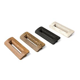
Our factory also produces:



What three LED profile sizes are needed before ordering a wooden cornice
For existing lighting, you need to record not one size, but three.
| Size | What does it mean |
|---|---|
Dtop
|
ceiling → top edge of LED profile |
Daxis
|
ceiling → profile axis |
Dbottom
|
ceiling → lower edge |
Additionally needed:
Hled = Dbottom − Dtop.
KZ‑005 occupies the wall up to the 110 mm mark from the ceiling. Comparing 110 with Dtop и Dbottom, you can accurately see whether the profiles do not intersect, the cornice overlaps only the top edge, covers part of the diffuser, or overlaps the profile entirely.
But a physical test is still needed: the light effect depends on the direction of the diodes, the geometry of the diffuser, the wall, and the observation point.
Get Consultation
Wooden ceiling plinth and ready-made lighting: what to adjust first
If the electrical work is already completed, the project logic changes. Moving the LED line means chasing, repairing the finish, reconnecting, and sometimes moving the power supply.
Therefore, the order is as follows:
-
check whether the KZ‑005 is compatible with the existing line;
-
if yes — keep the LED;
-
if no — compare the cost and risks of moving the LED versus replacing the cornice.
After geometry confirmation, you can buy a wooden cornice of the required scale, rather than forcing one model at any cost.
Can KZ-005 cover part of the aluminum LED profile?
Sometimes — yes. But only if the overlap was planned as part of the lighting assembly.
The LED profile is specially hidden behind a decorative cornice
Then KZ‑005 works as a screen. The light source remains invisible, and the light is reflected from the ceiling or wall.
The LED profile was designed as an independent visible line.
Then a random 10 mm overlap disrupts the geometry, covers part of the diffuser, changes the light, and complicates maintenance.
The main criterion is not "can the metal be covered," but whether the intended lighting function and service are preserved.
Why you cannot overlap the KZ-005 diffuser without checking the luminous flux
If the lower edge of KZ-005 covers the diffuser, the following may change:
-
light strip width;
-
brightness on the ceiling;
-
lighting direction;
-
visibility of LEDs;
-
Shadow boundary.
In one project the light will be softer, in another a hard horizontal shadow will appear. Therefore, an evening test is needed.
Full-size template KZ-005 110×40 mm: the cheapest test before purchasing a batch
The template must reproduce:
-
110 mm along the wall;
-
40 mm for MDF;
-
41 mm for beech/oak.
It can be made from foam board, cardboard, plywood, or an MDF offcut.
During the day, the actual overlap and access to the diffuser are checked. In the evening — shadow, brightness, visibility of LEDs, and the light strip. Only after this is it clear whether the conflict is a technical issue or a normal light screen.
Wooden cornice KZ-005 as a screen for hidden lighting: when geometry works in your favor
KZ-005 is interesting because it has a large height along the wall and a relatively small projection onto the ceiling. Therefore, it can work as a tall decorative screen without taking up too much ceiling space.
But this advantage only shows in a properly designed lighting scheme.
When KZ-005 really helps hide the LED
If the light source is located above the lower edge of the cornice and is directed:
-
up;
-
upward and slightly forward;
-
toward the ceiling,
KZ-005 can block direct view of the diodes.
When the cornice only gets in the way
If the LED profile is already designed for a visible diffuser, and KZ-005 accidentally overlaps its upper or lower part.
Why the general material about LEDs doesn't need to be repeated
The general technology is already covered in the article how to choose a ceiling cornice for LED lighting.
The new article answers a different question: what to do when the LED is already installed at 100 mm, and KZ-005 appears later.
When 40–41 mm of KZ-005 offset is not enough to hide the LED from direct view
Even if KZ-005 vertically overlaps the aluminum profile, the light source may remain visible from below.
This depends on:
-
the depth of the LED profile;
-
position of the strip inside;
-
height of the observer;
-
distance to the wall;
-
the angle of the diffuser;
-
ceiling height.
Simple geometric test
Stand up:
-
at the opposite wall;
-
in the center of the room;
-
in a sitting position.
If the light source or the bright diffuser line is visible under KZ‑005, the concealment is incomplete.
Why a universal "minimum setback" cannot be assigned
Because different profiles have different:
-
angles;
-
depth;
-
direction of light.
40 mm may work in one system and not work in another.
KZ-005 and the light strip on the ceiling: why an evening test is needed
During the day, you only evaluate the geometry.
In the evening, the following become apparent:
-
shadow from the bottom edge;
-
uneven brightness;
-
individual light points;
-
visibility of aluminum;
-
wall defects;
-
difference in trim color.
What to check
-
enable only LED;
-
turn off main light;
-
view from eye level;
-
walk along the wall;
-
check the corner of the room;
-
evaluate the ceiling above the cornice.
Why should the test be conducted specifically with the template
Without KZ-005, the light line may look perfect.
After adding the 110‑mm screen, the light will be distributed differently.
Should the LED profile be moved lower if KZ-005 overlaps it by 10 mm
Not automatically.
There are three options.
Leave the LED as is
If the template shows:
-
good light;
-
access to the diffuser;
-
access to the tape;
-
no issues with the driver.
Then the overlap can be a normal part of the light assembly.
Move the LED profile lower
Makes sense if:
-
KZ‑005 is essential;
-
the light line loses its function;
-
wall repair is still acceptable.
Choose a different cornice
If moving the electrical wiring is expensive, and another profile gives the desired look without conflict.
How to compare options
Not by the principle of "what is cheaper today," but by the total cost:
-
dismantling;
-
wall repair;
-
new finishing;
-
new cornice;
-
repeated electrical installation.
When a lower profile is more appropriate instead of KZ-005
If 110 mm objectively intrudes into the LED line, and the light unit cannot be changed, it is worth looking at Wooden ceiling cornices....
What to compare
-
height along the wall;
-
removal;
-
length;
-
material;
-
Scale.
Why you can't choose only the lowest
A profile that is too small can get lost in the room.
A balance is needed:
technical compatibility + architectural scale.
Why you cannot simply cut off the lower 10 mm from KZ-005
KZ-005 is a profiled product.
Longitudinal trimming of the lower part:
-
changes the cross-section;
-
disrupts the proportion;
-
may affect the decorative pattern;
-
complicates the corners;
-
creates a non-standard end along the entire length.
When individual reworking is possible at all
Only as a separate joinery solution after drawing and approval.
But this cannot be considered a standard way to "fit KZ‑005 to 100 mm."
Why changing the profile is usually cleaner
Another cornice retains the factory cross-section, angles, and predictable installation.
KZ-005 made of MDF under enamel: how to combine a cornice with a painted light wall
MDF KZ‑005 has:
110×40×2600 mm.
The current card shows the "Under enamel" preparation.
This is especially convenient if the cornice should be:
-
in the color of the wall;
-
to match the ceiling color;
-
a neutral background for light.
In the color of the wall
KZ‑005 is perceived as a continuation of the vertical plane.
In the color of the ceiling
The cornice visually connects more strongly with the top line.
If you want the decor to be the main accent of the room, paint it in a contrasting color relative to the walls. For example, white decor on dark gray or beige walls looks very striking.
Acceptable, but next to LED it enhances attention to geometry.
What to do with fresh ends
After cutting:
-
prime;
-
sand;
-
paint in the same system.
Especially if LED lights the end from the side.
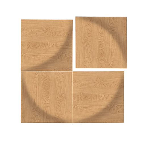
Natural wood baseboard KZ-005: oak or beech next to warm LED lighting
For natural finishing, you can use natural wood baseboard as a general molding context, but KZ‑005 remains a cornice.
Beech
KZ-005 made of beech:
110×41×2400 mm.
Current price:
9,970 RUB.
Oak
Same size:
110×41×2400 mm.
Price:
15,440 RUB
Why LED changes the perception of wood
Warm light enhances:
-
reddish shades of beech;
-
golden/brown shades of oak;
-
contrast of tinting.
What to do correctly
The material sample should be viewed:
-
at the actual LED temperature;
-
in the evening;
-
next to the wall and ceiling.
Why a daytime sample is insufficient
Oak that looks neutral during the day can become noticeably warmer in the evening.
KZ-005 2600 or 2400 mm: the LED line may change the cutting map
If the cornice runs continuously, the map is built along the perimeter.
If KZ‑005 has to be interrupted:
-
at the power supply;
-
at the revision;
-
near the LED profile;
-
in the technical area,
one long wall turns into several independent segments.
Why the material is chosen after the lighting solution
MDF — 2600 mm.
Wood — 2400 mm.
If the light gap creates two segments:
-
2500;
-
2500 mm,
MDF covers each with one plank, but beech/oak 2400 no longer does.
Conclusion
First, the LED unit.
Then the material.
Then the map.
Wall 5100 mm: how many KZ-005 to buy from MDF
Pure arithmetic:
2600 + 2600 = 5200 mm.
remains:
100 mm.
By total length, two planks seem sufficient.
But the map is almost zero
From 100 mm, you also need to account for:
-
end trimming;
-
corner cuts;
-
position of the central joint.
Straight wall scenario
If both edges are plain and the central joint is acceptable, two planks may suffice.
Scenario with two corners
Parts receive mitered ends.
A total allowance of 100 mm can no longer be considered guaranteed.
Practical conclusion
For 5100 mm, two MDF strips are a boundary map, not an automatic order.
The same wall and oak KZ-005 with a length of 2400 mm
Two planks:
2400 + 2400 = 4800 mm.
Missing:
300 mm.
Minimum:
3 planks.
But an LED gap can change the picture
If the light unit divides the wall into:
-
2400;
-
1700;
-
1000,
Three planks are distributed differently and yield more useful offcuts.
Why you can't just count "5100/2400"
Because specific segments may not fit in pairs.
Where to place the KZ-005 joint relative to the light line
Bad places:
-
right at the end of the LED;
-
under the brightest zone;
-
near the inner corner;
-
above the visual center of the wall.
Better:
-
less illuminated area;
-
above the cabinet;
-
near the architectural vertical;
-
where light does not slide along the joint.
Why LED amplifies the defect
Side light shows:
-
a micro-gap;
-
step;
-
difference in coloring;
-
putty.
Therefore, the joint location is part of the lighting inspection.
The LED power supply is hidden in the upper zone: can KZ-005 close the access for inspection?
This is a separate critical question.
If the driver/power supply is located behind the future KZ-005 and requires maintenance, a non-removable decorative cornice may block access.
What to find out
-
where exactly the unit is;
-
how to replace it;
-
where to pull it out from;
-
whether tools are needed;
-
whether there is a separate inspection hatch.
Cannot be considered
"The LED works, so no more climbing in there will be needed."
The power supply is a serviceable electrical component.
Practical rule
If access is needed through the same zone, KZ‑005 must:
-
not block it;
-
or be part of a removable structure.
The latter option needs to be designed separately.
Cornice KZ-005 and hidden wiring: what to check before drilling
Cables are already laid near the LED profile.
Before mounting KZ-005, you need to know:
-
the power route;
-
outlet location;
-
path to driver;
-
possible connections.
Why this is important
The cornice is high — 110 mm. The mounting zone on the wall may coincide with the electrical wiring.
What to do
Use the as-built diagram or a cable locator.
Do not drill blindly near an existing LED line.
When KZ-005 should not be bought at all with already installed lighting
KZ-005 is better not to buy if:
-
it blocks a critical part of the diffuser;
-
the light becomes worse;
-
the driver revision is covered;
-
installation requires sawing off the profile along its entire length;
-
the electrical cable runs through a conflict zone;
-
another cornice solves the task without redoing the lighting.
Why refusing KZ-005 is a normal outcome
An expert article should help not only to buy, but also to avoid buying an unsuitable profile in time.
The LED profile is not parallel to the ceiling: why the 100 mm size needs to be checked along the entire wall
In a real renovation, the lighting line may differ from the project.
Causes:
-
uneven ceiling;
-
marking on the wall without a laser;
-
change of level after puttying;
-
local trimming of the aluminum profile.
Example
Left:
99 mm from ceiling to top edge of LED profile.
In the center:
101 mm.
on the right:
96 mm.
KZ-005 ends at the 110 mm mark.
Nominal overlap:
-
left — 11 mm;
-
center — 9 mm;
-
right — 14 mm.
What is critical
Not the average 10 mm, but the maximum overlap at the worst point.
How to measure
Measure the distance:
-
at the beginning of the line;
-
at every corner;
-
at the power supply;
-
every 0.5–1 m on a long section.
If the ceiling is also uneven: the two error lines add up
LED can be installed exactly along the laser, but the ceiling may have a local wave.
KZ-005 is mounted to the actual wall and ceiling.
Therefore, in the section:
-
ceiling lowered by 3 mm;
-
LED remains on the previous line,
overlap increases by the same 3 mm.
Practical conclusion
Before ordering, a minimum actual Dtop is needed, not the design 100 mm.
How to check LED backlighting with a full-size strip along the entire wall
The local template shows the cross-section.
For a long wall, add simple marking with painter's tape.
Step 1
From the ceiling, measure down:
110 mm.
Draw a line for the future bottom edge of KZ‑005.
Step 2
Compare it with:
-
top of LED;
-
axis;
-
regulations;
-
revision.
Step 3
Mark the sections:
-
where KZ-005 overlaps the profile;
-
where it passes above;
-
where the conflict is especially strong.
Step 4
Place a volumetric template at the worst point.
What to do if KZ-005 only covers the upper metal edge, while the diffuser remains open
This is one of the most interesting boundary scenarios.
Perhaps the node is acceptable
if:
-
the light does not change;
-
the diffuser is removed;
-
tape is available;
-
the profile does not overheat;
-
visible metal is neatly covered.
The opposite result is also possible
KZ-005 may visually press the LED line and create too narrow a light gap.
How to solve
Not by millimeters, but through enabled light and service check.
What to do if KZ-005 covers part of the diffuser
This is a more serious conflict.
Need to check:
-
can the diffuser be removed;
-
whether the light angle has changed;
-
is there any local heating;
-
are the diodes visible;
-
can the strip be replaced.
When overlap can be part of the design
If the LED was pre-designed as hidden.
When is this a mistake
If the diffuser should be a visible architectural line.
What to do if KZ-005 completely covers the LED profile
Then you need to answer two questions:
Does the light go where it's needed?
Is service possible?
If the LED is completely hidden, but the light output is reflected on the ceiling and the driver is serviced separately, the unit can work.
If the LED is actually 'trapped' behind a non-removable profile, the solution is bad.
Can KZ-005 be made removable for access to the LED
Theoretically, yes, but this is already a non-standard design.
A regular ceiling cornice is usually mounted permanently.
A removable KZ-005 requires:
-
a separate base;
-
a hidden mechanical fastening;
-
precise repositioning.
Why this is more complicated than it seems
After several takes:
-
joints may stop aligning;
-
lacquer/enamel may get damaged;
-
corner joints lose precision.
When removability is justified
If there is indeed a serviceable unit behind KZ-005 and there is no other revision.
LED driver: why it cannot be locked behind a wooden cornice without access
The power supply is an element that may require replacement.
Even if the LED strip works for years, the driver remains a serviceable part.
What to check
-
whether it is behind KZ-005;
-
whether it can be removed;
-
whether there is a revision;
-
Is the cable length sufficient.
Strong scenario
Driver is placed outside:
-
into the cabinet;
-
a niche;
-
into the accessible hatch.
Then KZ-005 is not involved in the service.
Weak scenario
The driver lies behind the cornice, and the cornice itself is glued and puttied along its entire length.
How warm and cold LED change the choice of oak and beech
Color temperature of light affects wood.
Warm light
May enhance:
-
the golden tone of oak;
-
reddish shades of beech;
-
warm stain.
Neutral
Shows the material more calmly.
Cold
It can visually "dampen" warm wood and enhance contrast with a white wall.
Therefore
Oak/beech should be chosen under actual LED lighting, not just in the showroom.
KZ-005 under enamel and LED: where is the best place to do a test coat
For MDF, a small sample is sufficient.
Check:
-
wall color;
-
ceiling color;
-
light temperature;
-
matteness.
Why matte white enamel may look different
LED backlighting runs almost along the surface.
Side lighting shows more clearly:
-
orange peel;
-
sanding;
-
traces of putty.
Conclusion
The cornice finish near the LED requires more careful preparation than on a dark, unlit wall.
Wall 5100 mm: two MDF strips or three
Two MDF:
2 × 2600 = 5200 mm.
Remainder:
100 mm.
Without LED gap
If KZ‑005 runs continuously, this is a borderline but potentially workable map.
With a gap for inspection
Suppose we need to leave a free zone of 300 mm.
We get segments:
-
2400 mm;
-
2400 mm.
Then two strips are more suitable.
With a gap not in the center
For example:
-
2750 mm;
-
2050 mm.
MDF 2600 no longer gives the first solid piece.
A joint or a third plank is needed.
Main conclusion
The very fact of a gap does not always reduce consumption. Specific segments decide everything.
The same wall 5100 mm: beech/oak 2400 and LED break
Without a break:
Minimum three planks.
If the LED creates segments of 2300 + 2300 mm
Two planks of 2400 cover both parts.
That is, a service break can reduce the number of wooden planks from three to two.
Why this is a strong example
On a total length of 5100 mm:
5100 / 2400 = 2.125 → 3 strips.
But after excluding the central light/service zone, the actual length of KZ‑005 becomes 4600 mm, divided into two segments 2300+2300.
Then:
2 planks.
Practical value
The light unit changes not only technical compatibility but also the product basket.
An example where the total footage says "enough," but cutting requires more
Suppose, after all LED breaks, four segments are obtained:
-
1700;
-
1700;
-
1700;
-
1700 mm.
Sum:
6800 mm.
MDF
6800 / 2600 ≈ 2.62 → 3 strips.
But two 1700 mm parts do not fit into one 2600:
1700+1700=3400.
Actually needed:
4 slats.
Wood
6800 / 2400 ≈ 2,83 → 3.
Practically again:
4.
This is exactly the case when pure arithmetic gives the wrong order.
Example of a full room with LED gap
For example:
-
A = 2450 mm;
-
B = 1900 mm;
-
C = 1650 mm;
-
D = 900 mm;
-
E = 700 mm.
Sum:
7600 mm.
MDF 2600
Possible layout:
-
2450;
-
1900+700 = 2600;
-
1650+900 = 2550.
Total:
3 planks.
Beech/oak 2400
-
2450 does not fit as a whole;
-
1900+700 = 2600 do not fit;
-
1650+900 = 2550 do not fit.
A different layout with additional joints or more planks is needed.
What this shows
The 200 mm difference between SKUs is sometimes critical.
Cost of an example of three MDF KZ-005
Current price:
3,780 RUB
Three:
11,340 RUB
Beech
If the map requires four 2400 mm strips:
4 × 9,970 = 39,880 RUB
Oak
4 × 15,440 = 61,760 RUB
This is not a comparison of "which material is more cost-effective," but the commercial cost of specific maps.
Where to place the longitudinal joint relative to the LED
It is advisable to place the joint outside the brightest zone.
Bad option
The LED shines along the joint.
The shadow emphasizes:
-
a micro-gap;
-
drop;
-
difference in gloss.
Better
Joint:
-
above the cabinet;
-
next to a less illuminated vertical;
-
in an area where the light is directed differently.
If the LED ends 150 mm from the corner
The following appear simultaneously:
-
end of the aluminum profile;
-
KZ‑005;
-
inner corner miter cut;
-
wire.
This is a complex local junction.
Order
-
first the light;
-
then revision;
-
then angle;
-
only then the length of the cornice.
Why you can't cut the mustache first
It may turn out that KZ-005 needs to be finished earlier.
If the LED profile runs along only one wall
Then it is not necessary to change KZ‑005 around the entire perimeter.
Allowed:
-
select a different scenario on the LED wall;
-
run KZ-005 continuously along the other walls.
But you need to check how the line changes at the corners.
When it's better not to buy KZ-005 with already installed LED backlighting
KZ-005 should not be ordered if:
-
the profile unexpectedly covers the visible diffuser;
-
the light line becomes noticeably worse;
-
driver unavailable;
-
it is necessary to cut 10 mm longitudinally along the entire length;
-
the wiring is in the mounting area;
-
A lower cornice resolves the conflict more simply.
Expert choice allows for rejection of the product.
What to do if KZ-005 overlaps the LED by only 10 mm and the light looks normal
This is the most borderline scenario.
Physically, the lower edge of the cornice overlaps the upper part of the aluminum profile, but:
-
the diffuser remains visible;
-
the light strip is even;
-
driver is available;
-
the tape is replaceable;
-
cable is not pinched.
Then KZ-005 can be left
But this needs to be recorded as a deliberate overlap, not a random error.
What to write in the working drawing
-
Dtop;
-
Dbottom;
-
the overlap value;
-
diffuser position;
-
service access;
-
photo of the evening test.
Why this is useful
In a few years, another craftsman will understand that the cornice is not accidentally covering part of the profile.
What to do if the light is good, but the diffuser cannot be removed
Technically, the joint is still weak.
The diffuser may need to be removed for:
-
replacing the tape;
-
cleaning;
-
repairing the contact.
Options
-
make KZ-005 removable locally;
-
change the end point;
-
move the LED;
-
choose a different cornice.
What not to do
Do not rely on the fact that "the LED strip doesn't break."
Maintainability must be preserved.
If the driver is hidden not behind the cornice, but in the cabinet
This is a good scenario.
KZ-005 then does not participate in access to the power supply.
What remains to check:
-
the aluminum profile itself;
-
the tape;
-
diffuser;
-
the wire lead.
Why this simplifies the project
There is no need to do a revision in the cornice itself.
If the LED profile is in a groove and the diffuser is flush with the wall
KZ‑005 can cover it visually more cleanly than a surface-mounted aluminum profile.
But again:
-
light line changes;
-
access to the diffuser may disappear.
What to check
Place the template exactly on the finished wall after puttying.
If the aluminum LED profile protrudes from the wall
Then KZ‑005 may hit not only vertically, but also in thickness.
You need to measure:
-
profile protrusion;
-
actual protrusion of KZ‑005;
-
Mounting layer.
Why scheme 110 vs 100 is insufficient
It describes only the vertical conflict.
A volumetric profile requires a 3D check.
If the LED backlight is directed down the wall
In this case, KZ‑005 may block the light much more strongly.
The lower edge becomes a direct screen.
What can happen
-
short light strip;
-
hard shadow;
-
noticeable boundary;
-
reduction of illuminated height.
Conclusion
For downward-directed light, a particularly strict evening test is needed.
If the LED shines upward onto the ceiling
KZ‑005 potentially works better as a screen.
But you need to check:
-
visibility of diodes from below;
-
light spot width;
-
reflection height;
-
ceiling material.
Warm LED and oak KZ-005: how to avoid a too yellow interior
An oak under warm light can look significantly warmer than a daylight sample.
What to do
Do a test tinting on a short fragment.
Check:
-
2700–3000 K, if such a strip is already installed;
-
evening mode;
-
combination with the floor and furniture.
Why you cannot choose tinting only from a catalog
LED changes color perception.
Beech KZ-005 under enamel: when it is more rational than oak
If the goal is a painted cornice without visible wood texture, beech can be more reasonable than oak.
But in length, both:
2400 mm.
That is, the geometric map is the same.
KZ-005 made of MDF 2600 mm: when 200 mm of extra length really saves the plank
Suppose, after the LED gap, the parts:
-
2500;
-
2500;
-
900 mm.
MDF
-
2500;
-
2500;
-
-
| Ceiling → top of LED | Height of KZ-005 | Nominal result |
|---|---|---|
| 90 мм | 110 мм | KZ-005 overlaps by 20 mm |
| 100 мм | 110 мм | enters by 10 mm |
| 110 мм | 110 мм | lines coincide |
| 120 мм | 110 мм | 10 mm remains between the cornice and the LED |
Why 110 mm is not an automatic ideal
If the lower edge of KZ‑005 coincides with the top of the aluminum profile, you still need to check:
-
offset 40/41 mm;
-
visibility of LEDs;
-
diffuser;
-
service.
Why 120 mm do not guarantee good light
10 mm of free strip may be visually too small or, conversely, sufficient. The real light test decides.
Why 90 mm almost certainly requires a separate solution
20 mm of overlap already noticeably interferes with the existing light line. But even here, the final conclusion depends on the geometry of the LED profile itself.
If the size of 100 mm is taken to the axis: example with a 20 mm aluminum profile
This is a conditional calculation.
Let the height of the aluminum profile be:
20 mm.
The axis is at 100 mm.
Then:
-
top of the profile — 90 mm;
-
bottom — 110 mm.
KZ‑005 ends at 110 mm.
It turns out that vertically, the cornice potentially covers the entire height of the LED profile.
Why this example is especially important
A person who sees "100 mm" on the plan can expect a conflict of only 10 mm.
But if 100 mm is an axis, the real result is completely different.
Conclusion
Before purchasing, you must understand the project's dimension reference system.
If 100 mm is measured to the bottom edge of the LED profile
Then the entire profile is located above 100 mm.
KZ‑005 reaches 110 mm and can completely cover the aluminum element plus another 10 mm of wall below it.
When this may be acceptable
If the LED is initially hidden and the cornice works as a screen.
When this definitely changes the project
If the diffuser must be visible.
How to check the light line without dismantling the existing LED
If the profile is already recessed and the finishing is complete, there is no need to immediately tear down the wall.
Template
Cover the assumed KZ‑005 area with a cardboard mock-up.
Black tape
You can temporarily cover only the 10–20 mm of the diffuser that will fall under the cornice to see the effect of the overlap specifically.
The tape must not damage the diffuser.
Evening test
Compare:
-
original light;
-
light with KZ-005 imitation.
Photo with the same exposure
Useful for comparison, but the eye remains the main criterion.
If the LED profile is installed with a dimmer
Need to check several brightness levels.
At 100% power:
-
the shadow can be sharp.
At 20–30%:
-
the conflict almost disappears.
Why you can't test only one mode
The user will use different scenarios.
If KZ‑005 works only at minimum brightness, this limitation needs to be recognized in advance.
If the LED profile is color RGB/CCT
Different shades emphasize wood and wall differently.
Red/blue/cold white can more noticeably reveal:
-
end faces;
-
joints;
-
irregularities.
Therefore, for complex lighting, main scenarios are tested, not just warm white.
If there is a stretch ceiling nearby
KZ‑005 must be attached to a prepared base, not to the fabric.
With an existing LED line, additionally check:
-
ceiling baguette;
-
cables;
-
embedded parts;
-
heating;
-
driver access.
Why the topic becomes more complex
LED and stretch ceilings already have their own mounting zones. KZ-005 must not intersect them with its fasteners.
If the LED profile is on a drywall wall
Before mounting KZ-005, you need to know:
-
where the studs/embedded elements are;
-
where the cable is;
-
where the aluminum profile itself is.
You cannot drill near wiring based only on a visual line.
If the light line ends at a window or cabinet
The LED endpoint can be a good endpoint for KZ-005.
This allows:
-
tie the end to the architecture;
-
maintain the revision;
-
reduce random short fragments.
How to calculate reserve KZ-005 without mechanical 10%
If the card requires:
-
2 MDF at 2600;
-
or 3 wooden at 2400,
do not automatically add 10% of the footage.
Real choice:
-
an additional whole plank;
-
or absence of reserve.
When reserve is justified
-
borderline length 2550–2590 mm;
-
complex corners;
-
oak under clear finish;
-
repeat delivery is inconvenient.
When an extra plank is not needed
-
all parts are significantly shorter;
-
there are useful leftovers;
-
MDF under enamel;
-
reordering is simple.
Height of aluminum LED profile 10, 20 or 30 mm: how the actual overlap changes
If the 100 mm mark is given to the axis, the height of the aluminum profile directly changes the geometry. Let's consider three conditional profiles — only to demonstrate the method.
| Hled | Top edge at 100 mm axis | Bottom edge | KZ‑005 110 mm overlaps from the top edge |
|---|---|---|---|
| 10 мм | 95 мм | 105 мм | 15 мм |
| 20 мм | 90 мм | 110 мм | 20 мм |
| 30 мм | 85 мм | 115 мм | 25 мм |
Profile 10 mm
If the axis is at 100 mm, the top of the LED is at 95 mm. KZ‑005 reaches 110 mm, therefore, it vertically enters the profile zone by 15 mm.
At the same time, the bottom edge of the LED is at 105 mm, and the cornice goes down another 5 mm. This means it potentially covers not only the top of the metal housing, but also the entire vertical height of the LED profile itself. This needs to be checked against the actual overhang and the position of the diffuser.
Profile 20 mm
Top — 90 mm, bottom — 110 mm. The cornice ends exactly at the lower edge of the conditional aluminum profile.
On the drawing, this may look neat, but the service issue remains: can the diffuser be removed if a bulky KZ‑005 with a 40/41 mm overhang is placed in front of it.
Profile 30 mm
Top — 85 mm, bottom — 115 mm. KZ‑005 covers the upper part of the zone, but the lower 5 mm of the profile remain below the cornice.
Such a result may look the worst: part of the aluminum or diffuser remains visible as a thin strip. Therefore, "did not cover completely" does not mean "it turned out better."
What the table proves
Size 100 mm to the axis without Hled practically useless for making a decision. The same 100 mm can mean:
-
partial overlap;
-
almost complete closure;
-
visible bottom strip.
The actual size of the aluminum profile is needed.
Visible diffuser strip 5–15 mm: why this is a separate design problem
If KZ‑005 does not fully cover the LED, a narrow glowing or aluminum strip may remain at the bottom.
When it looks intentional
If the width is the same across the entire wall and the profile was designed as a thin light slit.
When it looks like a mistake
if:
-
the width changes due to unevenness;
-
the strip disappears at the corner;
-
in the center it is 12 mm, and on the right it is 5 mm;
-
it glows unevenly.
How to check
Run the KZ‑005 line with a template along the entire wall and measure the actual exposed part of the LED at several points.
If the width of the visible strip "wanders," simply installing KZ‑005 over an existing line is unlikely to give a clean result.
Revision not only of the driver: what else should remain accessible
When designing the service, you need to check not only the power supply.
Access may be needed to:
-
LED strip connectors;
-
wired output;
-
controller;
-
dimmer;
-
signal amplifier;
-
connector between sections.
If at least one serviced element is located directly behind the future KZ-005, it cannot be considered "hidden forever."
Practical checklist
Before the cornice, take photos of all electrical connections and note where access to them will be available after finishing.
Why this is useful in a few years
Even if the installer changes, the new specialist will see where the access point is and will not remove the cornice blindly.
LED profile on one wall and regular KZ-005 on the other three: how to handle corners
If the conflict is only on one wall, the scenario can be changed locally. But the corners between walls must be thought through.
Option 1. KZ-005 ends before the corner of the LED wall
Then on the adjacent wall, the cornice starts a separate line.
Option 2. The cornice goes around the corner, then ends at the start of the LED
Visually, it is usually calmer if the distance from the corner to the LED is sufficient.
What not to do
Leaving a piece of KZ-005 80–120 mm long between the corner and the start of the LED just for formal continuity. Such a fragment may look like a random offcut and complicate cutting.
Final procurement specification KZ-005
Before payment, it's useful to note:
KZ‑005 / material ___ / 110×40/41 mm / Dtop LED ___ / Daxis ___ / Dbottom ___ / overlap ___ mm / diffuser serviceable yes/no / driver accessible yes/no / light test passed yes/no / cornice segments ___ / strips 2400/2600 ___ pcs. / finish ___ .
What the specification must prove
-
100 mm have a clear reference point;
-
overlap calculated;
-
light is tested;
-
service is preserved;
-
unfolding performed after LED node decision.
If the wording remains:
"LED approximately ten centimeters from the ceiling,"
the purchase is not ready yet.
Inspection after final installation
After installation and painting of KZ‑005, the light test must be repeated: the actual mounting layer, actual profile position, and finish may change the shadow relative to the cardboard mockup. Enable all standard LED scenarios, remove and reinstall the diffuser, check access to the inspection hatch, and inspect the wall under side lighting. Only after this acceptance can the remaining offcuts be considered free reserve for other areas. If the actual light strip after installation differs from the test one in at least one section, first verify the position of KZ‑005, the height of the LED profile, and the uniformity of the wall, rather than masking the problem with local touch‑up or an additional overlay. This preserves the original geometry and allows understanding the true cause of the defect.
Final decision tree: can KZ-005 be installed with LED at 100 mm
Step 1. Is it known up to which point the 100 mm were measured?
-
no → measure;
-
Yes → continue.
Step 2. Is the height of the aluminum profile known?
-
no → measure;
-
Yes → continue.
Step 3. Has the actual overlap of KZ-005 been calculated?
-
no → calculate;
-
Yes → continue.
Step 4. Is the diffuser overlapped?
-
yes → mandatory light and service test;
-
No → continue.
Step 5. Does the light remain as intended in the evening?
-
no → move LED/another cornice;
-
Yes → continue.
Step 6. Are the diffuser and tape removed?
-
no → change the node;
-
Yes → continue.
Step 7. Is the driver available?
-
no → create a revision;
-
Yes → continue.
Step 8. Does the wiring not fall into the installation zone?
-
unknown → check;
-
Yes → continue.
Step 9. Is the material selected considering the length?
-
MDF 2600;
-
beech/oak 2400.
Step 10. Is a map of segments and joints built?
-
no → do not buy by the total perimeter;
-
Yes → continue.
Step 11. Only after this place the order.
FAQ
What is the size of KZ‑005?
MDF — 110×40×2600 mm. Beech and oak — 110×41×2400 mm.
How much wall space does KZ‑005 take up?
110 mm.
How much will it overlap the LED if the top of the profile is exactly 100 mm from the ceiling?
Nominally by 10 mm.
If 100 mm is specified to the axis, how much will the overlap be?
You need to know the height of the LED profile. Formula: 110 − (100 − Hled/2).
Can an aluminum LED profile be covered with a cornice?
Only if it is compatible with light and maintenance.
Can the diffuser be closed?
Only after checking the light pattern and the possibility of removing it.
Do I need to move the LED lower?
Not automatically. First a full-size template and an evening test.
Can 10 mm be cut off from KZ-005?
Not as a standard solution: longitudinal trimming changes the profile cross-section.
Why is a 110×40/41 mm template needed?
To see the actual overlap and light before purchasing the entire batch.
What to check in the evening?
Shadow, brightness, visibility of LEDs, evenness of the light strip, and joints.
Which material to choose — MDF, beech, or oak?
Based on finish and design after geometry confirmation. MDF — 2600 mm, wood — 2400 mm.
How does warm LED affect oak?
It enhances the warm tones of the wood, so the tinting is better assessed under actual light.
Can the power supply be covered by the cornice?
Only if separate service access is maintained.
How to calculate KZ‑005 for a 5100 mm wall?
MDF 2×2600 gives 5200 mm, but the map is borderline. Wood 2400 requires at least 3 slats without a break.
Can an LED gap reduce the number of planks?
Yes. For example, two segments of 2300 mm are covered by two wooden slats of 2400 mm.
Why does the total footage sometimes lie?
Because independent parts may not fit in pairs into one strip.
Where is the best place to place the KZ-005 joint?
In a less lit and architecturally justified area.
When is it better not to buy KZ-005?
When the light deteriorates, the service closes, or a deep longitudinal rework of the profile is needed.
Where to buy KZ-005?
In the current STAVROS card after checking the LED unit.
How to order KZ-005 after checking?
Transfer the material, actual LED dimensions, wall segments, and the final number of strips.
Short conclusion
Formula:
110 - 100 = 10 mm
is useful only as the first signal of a conflict.
If 100 mm is measured to the top edge of the LED profile, KZ-005 nominally overlaps it by 10 mm. If to the axis or bottom edge, the actual overlap will be different.
Correct sequence:
Dtop/Daxis/Dbottom → height of the aluminum profile → KZ-005 template → evening light test → diffuser → driver → wiring → material → 2400/2600 map → order.
KZ‑005 can be left in place if the overlap intentionally works as a light screen, the light strip remains high quality, and maintenance is accessible. If the cornice accidentally cuts the diffuser, covers the driver, or requires sawing off the bottom 10 mm along the entire length, it is better to move the LED line or choose a different cornice.
After the final check, KZ‑005 can be documented as a calculated element of the light architecture, rather than a profile that “almost matches” the 100 mm mark.