Article Contents:
- Wooden cornice KZ-005 110×40/41 mm: what dimensions need to be given to the electrician
- KZ‑005 made of MDF 110×40×2600 mm
- Beech KZ‑005 110×41×2400 mm
- Oak KZ‑005 110×41×2400 mm
- What to ask STAVROS before issuing an invoice
- Why 3D visualization does not replace a section
- The channel for wiring and the place for the LED profile are not the same thing
- Light is directed upward toward the ceiling
- Light works along the wall
- Need a soft reflected line without visible diodes
- Need a decorative visible light gap
- Physical check of KZ-005 before electrical installation
- Full-size template of KZ-005: the cheapest test before electrical installation
- Why the test should be done in the evening
- KZ-005 made of MDF under enamel: when it is especially convenient for integrated backlighting
- Why LED increases requirements for painting
- Fresh edges after cutting
- Oak KZ-005 with hidden backlighting: light makes natural wood more expressive
- What to agree on a sample
- Why the same color with LED off does not guarantee the same appearance in the evening
- Beech KZ-005: first the lighting scenario, then the finish
- Why a removable diffuser cannot be considered sufficient access for maintenance
- Cable exit point and prohibition of unauthorized modification of the finished profile
- Cable exit from the wall: the point must be tied to the approved section KZ-005
- What to pass on to the electrician
- Why you cannot groove the finished KZ-005 without approval
- Main LED wall 5200 mm and MDF 2600 mm
- Same wall 5200 mm and oak/beech 2400 mm
- Wall 4800 mm — reverse example
- Why the electrical connection does not need to be automatically placed at the KZ-005 joint
- Direct KZ-005 joints and continuity of the light line
- Direct junction of the cornice and light strip: how to avoid a visible 'light gap'
- When it is better to move the junction away from the center of the wall
- Driver, dimmer, and control: the service unit cannot be locked behind a stationary KZ-005
- Option: separate access hatch outside KZ-005
- Option: access through a removable adjacent element
- Why you should not design the entire KZ-005 as removable without necessity
- Base and hidden mounting plates: do not mix fastening with electrical work
- KZ-005 on a drywall wall: mounting plate for the cornice and channel for wiring are different tasks
- Mounting plate for fastening
- Cable route
- Why it's useful to keep a photo of the wall before it's sealed up
- Buying a wooden cornice: when profile KZ-005 can still be changed before electrical work
- Topic boundary: model selection and already installed LED are covered separately
- KZ-005 or KZ-007: model choice must be finalized before lighting design
- KZ-005 near an already installed LED profile: the reverse scenario is covered separately
- Who should not 'fill in the gaps' for someone else's part
- Why it's better to attach a drawing rather than a long text letter
- What not to buy before node confirmation
- When KZ-005 factory preparation is not needed at all
- Cable runs through the wall, and LED is mounted on a separate construction shelf
- Driver and wiring are in a separate accessible niche
- Backlighting is integrated into the ceiling system
- Why this needs to be clarified before requesting custom manufacturing
- If STAVROS does not confirm the required channel: three normal options
- LED and KZ-005 heat: do not use a decorative cornice as an arbitrary enclosed housing
- Continuous perimeter lighting
- Light ends before the corner
- Lighting only on one accent wall
- Prepared and standard segments on one perimeter
- Do not do individual preparation 'along the entire length' without a wall map
- Adjacent trim and painting system in one light test
- Wooden trim products near lighting: one light highlights several profiles at once
- STAVROS materials and product quality: what to coordinate with the painter before the light test
- Why the price of an individual channel cannot be determined in advance
- Example of purchase KZ-005 for a light wall 5200 mm
- MDF 2600 mm
- Beech 2400 mm
- Oak 2400 mm
- Partial and perimeter lighting: how to mark different segments
- If lighting covers only part of the wall: individually prepared KZ-005 must be separated from the standard one
- If lighting runs along the entire perimeter: a unified passport for each wall is required
- Hidden route after sealing: as-built diagram and transition through joints
- Cable passes through a straight joint of KZ-005: what to check before installation
- Why the installer needs an as-built diagram
- If the sequence of work has already been partially disrupted
- If the cable has already been routed, but the LED profile is not yet installed
- If KZ-005 has already been ordered as standard, and the channel was remembered later
- Timeline, payment, and logistics of custom KZ-005
- Payment and delivery of KZ-005: custom preparation requires separate timeline confirmation
- Why it is better to label light and regular slats
- Do not paint the non-standard batch before a trial fitting
- Multiple lighting zones and handover of the facility into operation
- If the lighting is divided into several independent zones
- Handover of the facility to the client: keep the as-built diagram of hidden lighting
- Why this is especially useful when selling or renting a property
- Mistake 1. First run the cable, then ask the manufacturer about the channel
- Mistake 2. Treating the channel for the cable as a ready-made niche for an LED profile
- Mistake 3. Coming up with the channel size on your own
- Mistake 4. Hiding the driver behind a non-removable KZ-005
- Mistake 5. Not checking the light with a full-size template
- Mistake 6. Using an MDF drawing for oak
- Mistake 7. Ordering a channel around the entire perimeter when the light is only on one wall
- Mistake 8. Placing an electrical connection at the cornice joint just "for convenience"
- Error 9. Not saving as-built photos of the cable and embedded parts
- Error 10. Painting the entire oak before the evening test
- Error 11. Treating the standard price of KZ‑005 as the full price of the light assembly
- Error 12. Not checking the angles
- Error 13. Leaving an unconfirmed channel in the working drawing after the manufacturer's refusal
- Error 14. Making KZ‑005 removable without necessity
- Error 15. Starting chiseling before the final choice of KZ‑005/KZ‑007
- Boundary scenarios before the final decision
- Boundary scenarios: when the same KZ-005 requires different solutions
- Light line only above the curtain
- The driver is in the cabinet on the adjacent wall
- The ceiling is already finished, but the walls are still exposed
- The walls are already covered with drywall, but not painted
- The light should change color or brightness
- The backlight is needed only as a night orientation aid
- Check before electrical installation and production
- Checklist before electrical installation
- What is the size of KZ-005?
- Can KZ-005 be used with recessed lighting?
- Can I order a channel for wiring?
- What size should the channel be?
- Can an LED profile be hidden in the same channel?
- What should be designed first — the electrical system or KZ-005?
- Where should the driver be located?
- Can the driver be placed directly behind KZ-005?
- Can I mill a channel into a finished KZ-005 myself?
- Is MDF KZ-005 suitable for white enamel?
- Can oak KZ-005 be used with LED?
- Why is MDF depth 40 mm, while oak/beech is 41 mm?
- Do I need to account for 2400/2600 mm when using backlighting?
- Can backlighting be done on only one wall?
- What to do if STAVROS does not confirm the required channel?
- Where can I see the current price of KZ-005?
- Where can I see a case where LED is already installed?
- Do I need to provide access to the LED strip?
- Final check before production launch: do the KZ-005 drawing and electrical project match?
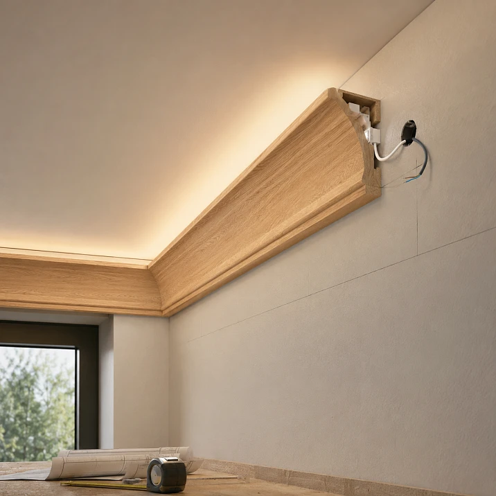
KZ‑005 has already been selected by the designer, hidden lighting is planned in the interior, but the electrician has not yet run the cable or installed the aluminum LED profile. This is exactly the best time to coordinate the assembly. The current KZ‑005 card directly states that hidden lighting is possible with embedded inserts and channels for wiring at the manufacturing stage. This means the sequence can be set up correctly: first, obtain a confirmed configuration of the specific KZ‑005 from the manufacturer, then tie the electrical work, light source, and service access to it — and only then start production and run the cable.
The main mistake is to first do the electrical work "roughly for a future cornice," and then order a standard KZ‑005 and try to adapt it on site. The card does not publish the channel dimensions, its exact position, allowable depth, shape of the embedded insert, or compatibility with any LED profile. Therefore, you cannot independently decide that it is enough to cut a groove of random size on the back side. Such a size would be made up.
The correct document before electrical installation is a working section of the assembly. It simultaneously shows the ceiling, wall, KZ‑005, location of the LED strip or aluminum profile, cable route, possible embedded insert, driver location, cornice mounting, and service area. After coordinating this section with STAVROS and the electrician, it becomes clear what exactly the manufacturer can prepare at the manufacturing stage and what remains part of the construction and electrical project.
If the profile has already been finally selected, you can buy wooden cornice KZ-005 after coordination of individual preparation. If the model is still being discussed, it is useful to first compare cornices in the general category — the article should not force KZ‑005 to work in an assembly that is better solved by another geometry.
Wooden cornice KZ-005 110×40/41 mm: what dimensions need to be given to the electrician
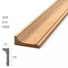
KZ‑005 has the same height of 110 mm in all current materials, but the depth and standard length differ. These parameters must be in the working section, not an approximate note "cornice about 110×40."
| Execution | Dimension A×C×L | Price at the time of check | Availability at the time of check |
|---|---|---|---|
| MDF | 110×40×2600 mm | 3 780 ₽ | SPb — 16 pcs. |
| Beech | 110×41×2400 mm | 9 970 ₽ | SPb — 68 pcs. |
| Oak | 110×41×2400 mm | 15 440 ₽ | Msk — 2 pcs., SPb — 19 pcs. |
For MDF in the current card, the sanding quality "Prestige" and re-lamination "Under enamel" are selected. The manufacturer specifies a rigid packaging frame at 390 ₽, up to five MDF products and up to two solid wood products per frame, as well as an average production time of 5–10 days for the missing item. Price and stock are dynamic; they need to be re-checked before payment.




KZ‑005 made of MDF 110×40×2600 mm
MDF is logical if the cornice must blend with a white ceiling or wall under a covering enamel. The 2600 mm length can reduce the number of direct joints compared to solid wood at 2400 mm, but this topic is secondary: first, the lighting and service unit must be resolved.
Our factory also produces:
Beech KZ‑005 110×41×2400 mm
Beech has a depth of 41 mm and a length of 2400 mm. The 1 mm difference in depth seems insignificant, but the working section must reflect the actual material.
Get Consultation
Oak KZ‑005 110×41×2400 mm
Oak is important not only for geometry but also for light. Side or sliding LED backlighting more strongly reveals the natural texture, tonal differences, quality of transparent finish, and direct joints.
KZ-005 with hidden lighting: what exactly the card confirms and what needs to be agreed upon separately
The card provides an important but brief statement: hidden lighting is possible with embedded elements and channels for wiring at the manufacturing stage. Only three conclusions can be confidently drawn from it.
- The manufacturer allows designing KZ‑005 as part of a hidden lighting assembly.
- Preparation must be planned before manufacturing, not improvised after delivery.
- Embedded parts and channels are subject to specific coordination.
This wording does not specify channel dimensions, maximum cable cross-section, position of the aluminum LED profile, thermal conditions, driver type, or mounting method for the modified cornice. All of this is either confirmed by the manufacturer or designed by specialized professionals.
What to ask STAVROS before issuing an invoice
- Is preparation possible specifically for the selected material KZ-005?
- What types of embedded parts and channels is the manufacturer ready to produce?
- What drawing is needed from the designer or electrician?
- What dimensions and positions can be coordinated?
- Does the modification affect the mounting of the cornice?
- Does it affect the visible cross-section?
- how the cost and timeline change;
- which part of the STAVROS unit it considers its area of responsibility.
Working section KZ-005 and hidden lighting: which elements should be on the same drawing
Before electrical installation, it is useful to make at least one cross-section at scale. It should show:
- finished wall;
- finished ceiling;
- KZ-005 with a real cross-section of 110×40 or 110×41 mm;
- mounting base/embedded cornice;
- LED strip or aluminum profile;
- direction of light flow;
- power cable;
- cable exit point;
- driver location;
- access to the driver;
- KZ-005 fastener;
- any assumed factory preparation of the profile.
Why 3D visualization does not replace a cross-section
Visualization shows the effect of light, but often does not include the actual thickness of the profile, cable, connection points, and access for maintenance. A beautiful glow in the image may be technically unserviceable.
Cable, LED profile, and driver: separating the functions of the assembly
The channel for wiring and the place for the LED profile are not the same thing
In a professional task, four different entities need to be separated: the electric cable route, LED strip or aluminum profile, driver, and service access. A channel that the manufacturer can prepare in KZ-005 for wiring does not automatically mean a ready-made niche for any LED profile.
The profile has its own geometry, diffuser, mounting, and manufacturer requirements. These parameters must be confirmed by the electrical project. The cable location can be permanently hidden, while the driver must remain serviceable. Therefore, a universal closed "groove for everything" without a node cut is a poor specification.
Light direction: first decide the effect, then the LED position relative to KZ-005
The phrase "hidden lighting behind the cornice" describes too many different lighting scenarios. Before ordering, it is necessary to understand which surface the source should illuminate and whether it should be completely hidden from typical viewing points.
Light directed upward at the ceiling
The cornice acts as a screen hiding direct view of the source. It is necessary to check whether the light strip does not end too close to the wall and whether a hard shadow from the upper geometry of KZ-005 appears. A universal distance between the strip and the cornice does not exist here: it depends on the LED profile, beam angle, room height, and ceiling reflectivity.
Light works along the wall
The source is positioned to emphasize the vertical surface. In this scenario, the relief of KZ-005 can cast a noticeable shadow, and the cable and mounting must not fall into the light cone.
A soft reflected line without visible diodes is needed
It is necessary to check not only the source position but also the view from sitting and standing positions. Even if the LED is hidden from a person at the opposite wall, it may be visible from a ladder, sofa, or adjacent room.
A decorative visible light gap is needed.
Then KZ-005 should not accidentally overlap the diffuser. This is no longer just a "hidden LED," but a separate lighting architecture with a controlled visible line.
Physical check of KZ-005 before electrical installation
Full-size template for KZ-005: the cheapest test before electrical installation
Before ordering custom preparation, it is useful to make a short cross-section mock-up. For MDF — 110×40 mm, for beech/oak — 110×41 mm. The template is applied to the future cornice line and the light source is temporarily simulated.
Such a test does not replace an electrician's calculation, but it answers important visual questions:
- is the source visible from below;
- how does the reflected strip on the ceiling look;
- is the profile overhang sufficient as a light shield;
- does the cornice block future access;
- how light emphasizes the relief and joints.
Why the test should be done in the evening
During the day, only the geometry is easy to assess. In the dark, light points, uneven brightness, random shadows, and the visibility of the aluminum profile become apparent.
Material and finish KZ-005 in a lighting scenario
KZ-005 made of MDF under enamel: when it is especially convenient for integrated backlighting
Current KZ-005 made of MDF 110×40×2600 mm in the card it is listed as "Prestige / Under enamel." This option makes sense when the cornice should visually blend with the ceiling or wall, and the accent is created by light, not by natural wood texture.
If the project has a lot of painted moldings, it is useful to simultaneously buy MDF moldings one material logic and coordinate the overall painting system.
Why LED increases requirements for painting
Sliding light more strongly reveals sanding marks, differences in gloss, fresh cut ends, and direct joints. Therefore, a test finish should be viewed not only under general ceiling light, but also with the future backlighting turned on.
Fresh cut ends after cutting
After cutting, the factory preparation no longer covers the new cut end. It is finished in the same system as the face surface. If LED runs along the cut end, insufficient preparation will be especially noticeable.
Oak KZ-005 with hidden backlighting: light makes natural wood more expressive
If the interior is built around natural oak, oak cornice KZ-005 110×41×2400 mm should be checked together with the future light. Evening backlighting can more strongly reveal porosity, tonal transitions, and differences between adjacent slats.
What to approve on the sample
- tinting or clear finish;
- light direction;
- gloss level;
- visibility of the direct joint;
- the reaction of the end face to the finish.
Why the same color with LED off does not guarantee the same appearance in the evening
Side light changes the perceived contrast of the fibers. Two planks that seem close during the day may differ more in the evening. Therefore, paired parts are distributed across walls before the finish.
Beech KZ-005: first the lighting scenario, then the finish
Beech has the same solid wood geometry of 110×41×2400 mm. It can be used under enamel or another agreed finish, but the sequence remains the same: lighting effect → light source location → real material sample → finish → final order.
Do not choose beech just because it is between MDF and oak in price. In the lighting node, compatibility with the overall interior system is more important.
Hidden lighting driver: where to leave service access
The driver is a separate serviceable component. The cornice should not turn it into an inaccessible part that can only be replaced after destroying the finish. The location of the power supply is determined by the electrical design and the equipment manufacturer's requirements.
Before ordering KZ-005, you need to know:
- where the driver is located;
- which element opens for access;
- can the block be removed/replaced after finishing;
- does the cornice overlap the inspection cover;
- how does the cable run from the driver to the LED;
- does the connection fall into an unserviceable enclosed cavity.
Why a removable diffuser cannot be considered sufficient inspection access
The LED profile diffuser may provide access to the tape itself, but not necessarily to the driver or cable connections. Each serviceable part is checked separately.
Cable exit point and prohibition of unauthorized modification of the finished profile
Cable exit from the wall: the point must be tied to the approved section KZ-005
Before the electrician starts chasing, the position of the cable exit is easy to correct on the drawing. After finishing, the mistake becomes expensive. The point should be determined not by an approximate height of 110 mm, but by the actual assembly with the selected material and confirmed factory preparation.
What to tell the electrician
- article KZ-005;
- the material;
- actual cross-section 110×40 or 110×41;
- drawing of the agreed channel/embedded part;
- position of the LED profile;
- driver location;
- service diagram;
- cable route.
Installation and connection are performed by a qualified electrician according to the equipment documentation. The article does not specify the cable cross-section, protection type, driver power, or connection method — these parameters depend on the specific electrical system.
Why you cannot groove a finished KZ-005 without approval
If a standard cornice has already arrived, do not independently cut a large groove on the back side, reduce the working cross-section, or move mounting zones just for the wiring.
Such intervention may:
- weaken the profile;
- change the contact plane;
- cross the mechanical fastening point;
- alter the visible geometry;
- deprive the project of its pre-agreed technological logic.
If modification is needed after delivery, it must first be coordinated with the manufacturer or designer. The fact that the FAQ allows channels at the manufacturing stage is not permission for arbitrary milling of the finished product.
KZ-005 2400 or 2600 mm: joint locations must be coordinated together with the light route
The length of the strips becomes important not because the article is about cutting. A direct joint of the cornice is an area where the light line, cable, and finish must pass without accidental conflict.
Main LED wall 5200 mm and MDF 2600 mm
Here the geometry is ideal:
2600 + 2600 = 5200 mm.
This results in one straight cornice joint. If the light line is also continuous, this joint can be placed in a calm zone in advance, avoiding unnecessary short wooden/MDF pieces.
The same wall of 5200 mm and oak/beech 2400 mm
2400 + 2400 = 4800 mm.
400 mm is missing. At least three mounting pieces and two straight joints. The 400 mm extension can be obtained from the offcut of another wall, so the number of whole purchased slats depends on the overall layout, but the light wall itself becomes more fragmented.
Wall of 4800 mm — the opposite example
Oak/beech:
2400 + 2400 = 4800 mm.
MDF:
2600 + 2200 = 4800 mm.
Both options have one straight joint. Here, the length of 2600 mm does not provide an architectural advantage.
Why the electrical connection does not need to be automatically placed at the KZ‑005 joint
The cornice joint and the connection of lighting equipment solve different tasks. Wooden parts can join at one point, while the LED line can run continuously. If the electrical design includes a connection, it is placed according to equipment requirements and service accessibility, not because the KZ‑005 plank ends nearby.
Straight joints KZ-005 and continuity of the light line
Straight cornice joint and light strip: how to avoid a visible "light gap"
Even if the mechanical joint is made perfectly, light can make it noticeable. This happens when the distance from the source to the ceiling changes nearby, a shadow appears, or the edge of one plank has a slightly different geometry.
Before launching the entire batch, it is useful to test one joint with real light. On the mock-up, evaluate:
- whether a dark vertical stripe appears;
- whether brightness changes immediately after the connection;
- whether a fresh end is visible under enamel or tinting;
- whether a break in the aluminum profile falls at this spot;
- whether there is access to the lighting equipment after final finishing.
When it is better to move the joint away from the center of the wall
If the main light line is above a fireplace, bed, sofa, or a long TV composition, the joint along the central axis may be more noticeable. The cutting layout should account for the architecture, not just waste.
Driver, dimmer, and control: the service unit cannot be locked behind a stationary KZ-005
The system may contain a driver, dimmer, controller, or other components. Their composition depends on the project. The main rule for the article is simple: components that must be serviced or replaced cannot be made accessible only after destroying the cornice and finish.
Option: separate access hatch outside KZ-005
The clearest scheme is when the serviceable electronics are located in an accessible niche, cabinet, ceiling access point, or another designated location. Then KZ-005 remains a stationary decorative element.
Option: access through a removable adjacent element
Possible if specifically designed and confirmed. A randomly removable molding cannot be considered an "access hatch" if after several openings it loses joint precision or damages the enamel.
Why you should not design the entire KZ-005 as removable without necessity
The cornice runs along a long line and has corner joints. Regular removal can disrupt the geometry of the joints and the finish. If service can be moved to a separate point, this is usually more logical.
Hidden lighting and stretch ceiling: three systems must be laid out on one section
If the room has a stretch ceiling, the upper zone already has a ceiling baguette, the membrane, possible embedded elements, and electrical wiring. KZ-005 must not be attached to the membrane and must not intersect hidden elements of the ceiling system without a project.
The section must simultaneously show:
- actual position of the stretch ceiling;
- ceiling baguette;
- base for KZ-005;
- LED profile;
- cable;
- embedded elements;
- service access.
Do not transfer universal dimensions from one stretch ceiling to another. The specific geometry is provided by the ceiling system installer.
Base and hidden embedded elements: do not mix mounting with electrical wiring
KZ-005 on a drywall wall: embedded element for a curtain rod and channel for wiring are different tasks
A plasterboard box is often built simultaneously with lighting. In this case, it is easy to mix two functions: the structural base for mounting KZ‑005 and the void/channel for the cable. They can be located nearby, but are designed separately.
Mounting plate for fastening
It must provide the installer with a reliable structural zone in places where the KZ‑005 scheme and the wall base require it. The type, size, and fasteners are determined by the project.
Cable route
It must run in such a way that subsequent cornice mounting does not cross the electrical wiring. On the working diagram, the route is marked separately from the mounting plate.
Why it is useful to keep a photo of the wall before cladding
As-built photo documentation helps the installer understand where the mounting plates and cables run, especially if KZ‑005 is installed several weeks after the electrical work.
Buy a wooden cornice: when the KZ-005 profile can still be changed before electrical work
If the working cross-section shows that KZ‑005 requires complex non-standard modification, blocks the light flow, or creates inconvenient service access, it is better to open the category before chasing and buy a wooden cornice another geometry after comparison.
Electrical work is not done yet — meaning the project has maximum freedom. It is now that it's easier to change the cornice than after installing the LED profile and finishing the wall.
Topic boundary: model selection and already installed LED are covered separately
KZ-005 or KZ-007: model choice must be finalized before lighting design
If the designer is still undecided between two profiles, there is no need to develop a channel and mounting plate for KZ-005, only to change the model a week later. The comparison is already covered in a separate material KZ-005 or KZ-007.
The lighting engineering assembly begins only after the final choice. KZ-007 has a different height and a different depth in solid wood, so the KZ-005 drawing cannot be used as a universal one.
KZ-005 near an already installed LED profile: the reverse scenario is already covered separately
If electrical work is already done and the LED profile is installed 100 mm from the ceiling, the task changes completely. There, you first measure the existing line and check whether the 110-mm KZ-005 will cover it. There is a separate article for that KZ-005 near an already installed LED profile.
This material deliberately considers the opposite sequence: while electrical work is not done, the cornice and lighting can be designed as one assembly.
Who is responsible for what in the KZ-005 + hidden lighting assembly
Errors often arise not from complex geometry, but from blurred responsibility. The designer believes the channel will be determined by the manufacturer; the manufacturer waits for a drawing; the electrician runs the cable "on site"; the KZ‑005 installer gets an already closed wall. To prevent this, it is useful to divide roles before the first order.
| Participant | What should be confirmed |
|---|---|
| designer/architect | visual effect, KZ‑005 position, light direction, visible lines |
| STAVROS | feasibility of specific factory preparation, geometry of the agreed modification, timeline and cost |
| electrician/lighting engineer | cable, LED equipment, driver, control, service and electrical safety |
| construction crew | wall/ceiling base, embedded parts, actual dimensions and as-built geometry |
| profile installer | joints, corners, fastening, and conformity of the actual part to the approved drawing |
| Painter | preparation of fresh cuts and finishing in a real lighting scenario |
Who should not 'fill in the gaps' for someone else's part
The electrician should not set the depth of the factory channel in KZ-005 without manufacturer confirmation. The cornice manager should not choose the driver's power and location. The installer should not relocate the cable on installation day. Each boundary is fixed by a document.
Technical specification for individual preparation of KZ-005: what to attach to the request
The more precise the request, the lower the chance of getting a 'check with the electrician' response. The minimum package can be compiled on a single sheet.
| Field | What to specify |
|---|---|
| Article number | KZ‑005 |
| Material | MDF / beech / oak |
| Size | 110×40×2600 or 110×41×2400 mm |
| Room | specific room/zone |
| lighting effect | upward / onto the ceiling / along the wall / according to the attached section |
| equipment | LED profile/tape model and documentation |
| cable | type and route per electrical project |
| assumed preparation | show on drawing, do not assign without approval |
| Embedded part | location and function per project |
| driver | location and access method |
| wall lengths | final values |
| Finish | enamel / tinting / transparent |
| question to the manufacturer | confirm possibility, dimensions, price, timeline, and impact on installation |
Why it's better to attach a drawing rather than a long text letter
The phrase "the cable must run behind the cornice" doesn't indicate which part of the profile it's in or where it ends. A cross-section with dimensions allows the manufacturer to see the conflict with their own product and give a specific answer.
Before confirming the joint: what's too early to buy and what to do if modification is refused
What not to buy before confirming the joint
To avoid locking in incorrect geometry, some components are better not ordered definitively until approval.
- the full batch of KZ-005 with individual preparation;
- the entire volume of LED profile, if its dimensions haven't been verified in cross-section yet;
- cable outlets "at cornice height" without marking;
- embedded parts, if their size depends on the refined profile;
- painting scheme, if the light can still change color/gloss.
At the same time, you can select equipment in advance and obtain its technical documentation. The difference between "choosing a model" and "physically installing" is fundamental.
When factory preparation KZ-005 is not needed at all
The presence of a hidden lighting option does not mean that any project should order a channel inside the cornice.
The cable runs in the wall, and the LED is mounted on a separate construction shelf
KZ-005 can only work as a decorative light screen. Then individual milling of the profile itself may be unnecessary.
The driver and wiring are located in a separate accessible niche
If only a short lead to the LED unit fits KZ-005 and it does not conflict with the mounting, a special long channel may not be required.
The lighting is built into the ceiling system.
The cornice visually interacts with light, but the electrical part is completely outside it. In this case, the task comes down to geometry and a light screen.
Why this needs to be clarified before requesting custom manufacturing
Any non-standard operation can affect price, timeline, and installation. If the function is solved by the building structure without interfering with KZ‑005, a complex order provides no additional benefit.
If STAVROS does not confirm the required channel: three standard options
A negative response from the manufacturer does not mean a dead end.
- Move the cable into the building structure. KZ‑005 remains standard.
- Modify the LED unit. For example, choose a separate shelf/recessed structure without affecting the profile — the specific solution is designed by a specialist.
- Choose a different cornice. If the geometry of KZ‑005 is fundamentally incompatible with the task, changing the profile is easier before electrical installation.
The weakest option is to buy a standard KZ‑005 and then deeply mill it in a workshop without confirmation.
Thermal regime and equipment safety
Heat LED and KZ-005: do not use decorative cornice as an arbitrary enclosed housing
LED strip, aluminum profile, and driver have their own manufacturer requirements for installation and thermal regime. Card KZ-005 does not provide data that would allow declaring a specific enclosed volume safe for any equipment.
Therefore, in the technical specification, it is necessary to distinguish:
- decorative light shielding;
- location of the LED profile itself;
- heat dissipation according to equipment documentation;
- position of wooden/MDF profile;
- service.
Do not place the driver or LED equipment in an unverified enclosed cavity just because there is physically space there.
Room corners: the channel and light line must pass through the turn predictably
On a straight wall, the cut looks simple. In an internal or external corner, KZ‑005 is cut, and the light node must either continue or end deliberately.
Continuous lighting around the perimeter
You need to check the turn of the LED system, the cable, and access to the connection. The miter joint KZ‑005 itself does not solve the electrical part.
Light ends before the corner
The end point must be defined on the facade. The cornice can continue without lighting, but the brightness transition should look intentional.
Lighting only on one accent wall
This often simplifies service and cutting. But in the corner, you need to understand where the light cavity ends and how a regular KZ‑005 connects to the prepared section.
Prepared and standard segments on the same perimeter
Do not do individual preparation "along the entire length" without a wall map
If hidden lighting is only needed on one wall, there is no reason to automatically order a channel on all KZ-005 around the perimeter. The work sheet may contain two types of parts:
- KZ-005 with agreed preparation — only on the light wall;
- standard KZ-005 — on the remaining sections.
This decision must be coordinated with the manufacturer: the custom and standard parts must match in visible geometry and finish. But this approach allows not to complicate the entire order for the sake of one light section.
Adjacent trim and painting system in one light test
Wooden trim products near lighting: one light highlights several profiles at once
If KZ-005 is adjacent to moldings, casings, or wall panels, the side LED can illuminate not only the cornice. The entire set wooden trim items needs to be checked in one evening test.
Otherwise, KZ-005 will be perfectly painted, but the adjacent molding will turn out more glossy and start reflecting light in patches. One color code does not guarantee the same appearance on different profiles.
Materials and quality of STAVROS products: what to coordinate with the painter before the light test
Section Materials and quality of STAVROS products explains the differences between "Standard/Prestige" and "under enamel/under tinting". For hidden lighting, these parameters are especially important because directional light increases the visibility of surface preparation.
A painter needs to know:
- what material KZ‑005 is;
- what the factory sanding is;
- what type of re-lamination;
- whether there will be fresh edges after cutting;
- what direction the LED is;
- what degree of gloss is needed.
KZ-005 price: base cost of the profile — only one line of the light unit
At the time of checking, standard versions cost 3,780 ₽ for MDF, 9,970 ₽ for beech, and 15,440 ₽ for oak. Current KZ-005 price needs to be rechecked right before the invoice.
But the cost of a standard strip is not the price of a finished cornice with hidden lighting. The budget may include:
- the KZ-005 batch itself;
- individual preparation, if confirmed;
- LED strip/profile;
- cable;
- driver and control;
- embedded elements and construction preparation;
- KZ-005 finishing;
- installation of linear elements;
- electrical installation;
- inspection unit.
Why the price of an individual channel cannot be determined in advance
The card does not publish a fixed price for a specific modification of hidden lighting. The cost depends on the confirmed operation and order. Therefore, the article should not write "the channel costs X rubles" without a commercial offer from the manufacturer.
Example of purchasing KZ-005 for a light wall of 5200 mm
If the backlight runs along only one straight wall 5200 mm long, the base card depends on the material.
MDF 2600 mm
2600 + 2600 = 5200 mm.
Two strips, one straight joint. Base profile cost at the time of verification:
2 × 3 780 = 7 560 ₽.
Beech 2400 mm
Two full lengths give 4800 mm, an additional 400 mm is needed. If it cannot be obtained from the remainder of another wall, a third strip is required for one isolated light wall. Base cost of three:
3 × 9 970 = 29 910 ₽.
Oak 2400 mm
Same geometry 2400+2400+400 mm. Three strips:
3 × 15 440 = 46 320 ₽.
In the overall perimeter, the 400 mm addition can be obtained from another remainder, so this calculation cannot be transferred to the entire project. Its purpose is to show how a 5200 mm light wall interacts with the purchase length.
Partial and perimeter lighting: how to mark different segments
If lighting only covers part of the wall: the individually prepared KZ-005 must be separated from the standard one
Suppose the wall is 5200 mm, but the light line is only 3200 mm long. You cannot automatically order all 5200 mm with the channel. First, determine where the prepared part ends and how it connects to the standard KZ-005.
In the specification, it is convenient to divide:
| Detail | Function | Preparation |
|---|---|---|
| L1 | lighted section | according to the agreed drawing |
| L2 | continuation of the cornice without light | standard KZ-005 |
The junction point should be chosen as a regular visible joint and should not accidentally coincide with the electrical connection if this worsens service.
If lighting runs along the entire perimeter: a unified passport for each wall is needed
For a room with four light walls, it is convenient to assign codes A, B, C, D to the segments. For each, record:
- the finished length;
- material KZ-005;
- number of planks;
- the location of the direct joint;
- cable exit point;
- light direction;
- driver location;
- the presence/type of agreed preparation;
- the corner transition.
This way, the electrician and the installer do not work according to different diagrams.
Hidden route after sealing: as-built diagram and transition through joints
Cable passes through a direct joint KZ-005: what to check before installation
If the route runs behind several cornice parts, each direct joint must remain technologically neutral for the cable. The edge, fasteners, or adhesive must not accidentally press on the wiring.
This does not mean that the cable must have a connection at every joint. On the contrary, the number of electrical connections is determined by the electrical design. But the physical path of the wire must be compatible with the KZ-005 layout.
Why the as-built diagram is needed by the installer
A month after the electrical work, the location of the hidden cable is no longer visible. The curtain rod installer must receive the exact route or a photo before closing to avoid drilling in an unknown area.
If the sequence of work has already been partially disrupted
If the cable has already been routed out, but the LED profile has not yet been installed
This is an intermediate scenario. There is less freedom than before the electrical installation, but more than after the full LED installation.
You need to:
- record the actual exit point;
- overlay the real KZ-005 cross-section onto it;
- check whether an agreed preparation is possible;
- if necessary, adjust the LED profile around the existing exit;
- Do not continue installation until the service node is resolved.
If KZ-005 has already been ordered as standard, and the channel was remembered later
First, you need to clarify the production status. If the order has not been started yet, the specification may be changed. If the cornice has already been manufactured, the modification option must be agreed upon separately.
You should not automatically assign the carpenter to "select a channel" in the finished part. You need to compare:
- actual cross-section;
- installation area;
- remaining material thickness;
- need for warranty approval;
- a real alternative — run the cable in the wall.
Hidden lighting must be serviceable after painting and handover of the interior.
On the day of acceptance, the system may work perfectly. The expert unit is also evaluated by what happens during the first replacement of the tape or driver.
Verification scenario:
- shut down the system according to the prescribed procedure;
- gain access to the serviced component;
- remove it without damaging KZ‑005;
- replace/check;
- return the decorative unit without repainting work.
The actual procedure is determined by the equipment and the electrical design. But if the drawing provides no answer at all to the question "how to replace," the project is incomplete.
Timeline, payment, and logistics for custom KZ-005
Payment and delivery of KZ-005: custom preparation requires separate confirmation of the timeline
Standard
A good article result is not necessarily the purchase of KZ-005. If the node is not confirmed, changing the solution before electrical installation is much cheaper.
Acceptance of KZ-005 with individual preparation: must be checked against the approved drawing
If the manufacturer has confirmed a special channel or embedded part, acceptance differs from a regular profile check. It cannot be limited to the size 110×40/41 mm and the number of planks. Each non-standard part must be compared with the agreed production scheme.
Checked:
- article number and material;
- length of a specific plank;
- visible profile cross-section;
- presence of agreed preparation where it should be;
- absence of preparation on standard segments if the order is split;
- orientation of the channel relative to the front side;
- compatibility with the approved cable exit point;
- Surface integrity after transportation.
Why it is better to mark light and standard slats
If they look the same externally, an installer may confuse them. The S1, S2 list for light components and N1, N2 for standard ones eliminates the situation where a channel ends up on a wall without LED, and a light wall receives a standard slat.
Do not paint a non-standard batch until a test fitting
First, it is worth attaching at least one prepared component to the wall mockup and ensuring that the cable, LED assembly, and fasteners do not conflict. After final enamel, correcting production geometry is significantly more expensive.
Multiple light zones and handover of the object for operation
If the lighting is divided into several independent zones
A large hall may have light only above the fireplace, curtain, and TV area. These sections do not necessarily have to form one continuous electrical circuit. For KZ‑005, something else is important: each zone must have its own start/end point on the facade and clear service access.
In the specification, it is convenient to record:
| Zone | Crown Molding | Light | Service |
|---|---|---|---|
| S1 | KZ‑005 with confirmed preparation | As per project | revision R1 |
| N1 | standard KZ-005 | No | Not required |
| S2 | prepared KZ-005 | As per project | revision R2 |
So the electrician does not assume that the channel exists along the entire perimeter, and the installer understands which parts cannot be swapped.
Handover of the object to the client: keep the as-built diagram of the hidden lighting
After the renovation is complete, all cables, embedded parts, and channels become invisible. Therefore, along with the interior, it is useful to hand over a short package of documents to the owner:
- final section KZ-005 + LED;
- route of the hidden cable;
- location of the driver and access point;
- model of the LED equipment;
- photo before closing the wall/cornice;
- marking of light segments KZ-005;
- formula for final painting or tinting.
In a few years, this information allows servicing the lighting without drilling the cornice blindly or opening the finish to find the power supply.
Why this is especially useful when selling or renting a property
A new user does not know where the driver is hidden or how the wiring runs. An as-built diagram turns a design solution into a maintainable system, not a "secret inside the wall."
Typical mistakes when ordering KZ-005 for future hidden lighting
Mistake 1. Run the cable first, then ask the manufacturer about the channel
The electrical point is fixed before the cornice geometry. If the factory preparation ends up in a different place, you will have to move the outlet or build a complex bypass.
Mistake 2. Treating the cable channel as a ready-made niche for an LED profile
Cable and light profile are different elements. Their dimensions, mounting, and maintenance are coordinated separately.
Error 3. Inventing the channel size on your own
The card does not publish universal width and depth. A confirmed drawing of a specific order is required.
Error 4. Hiding the driver behind a non-removable KZ-005
During the first replacement, the finish will have to be destroyed. Service access must exist before installation.
Error 5. Not checking the light with a full-size template
In the visualization, the source is hidden, but from the sofa area, the diffuser or a bright line may be visible.
Error 6. Using an MDF drawing for oak
The depth changes from 40 to 41 mm, the length from 2600 to 2400 mm. This must be taken into account in the dense node and joint map.
Error 7. Ordering a channel around the entire perimeter, although the light is only on one wall
Individual operation complicates and increases the cost of extra parts. Prepared and standard segments need to be separated in the bill of materials.
Mistake 8. Installing an electrical connection at the cornice joint just "for convenience"
Connection points are determined by the electrical design and accessibility, not by cutting the wooden profile.
Mistake 9. Not saving as-built photos of the cable and embedded parts
The installer later does not know where the safe mounting zone is.
Mistake 10. Painting the entire oak before the evening test
Sliding LED can unexpectedly amplify the difference in shade and gloss.
Mistake 11. Considering the standard price of KZ-005 as the full price of the light assembly
Individual preparation, electrical work, LED, driver, finishing, and installation are calculated separately.
Mistake 12. Not checking the angles
On a straight wall, the channel and light work, but in an inner corner, the route and profile conflict.
Error 13. Leaving an unconfirmed channel in the working drawing after the manufacturer's refusal
The electrician will continue working according to the outdated scheme. The project revision must be issued officially.
Error 14. Making KZ‑005 removable without necessity
Long joints and corners are poorly suited for regular dismantling. It is better to move the inspection to a separate unit.
Error 15. Starting chiseling before the final choice of KZ‑005/KZ‑007
Changing the model changes the geometry of the light screen. First the model, then the electrical work.
Boundary scenarios before the final decision
Boundary scenarios: when the same KZ-005 requires different solutions
Light line only above the curtain
The cornice can run along the entire perimeter, but preparation is only needed on one section. Then you should not automatically order a custom channel in all slats. It is only important to determine in advance the transition point from the prepared segment to the standard one and check that it does not fall into a corner.
The driver is in the cabinet on the adjacent wall
This can simplify service: the power supply remains accessible, and only a confirmed route to the LED passes through KZ‑005. But the length and method of cable routing are still determined by the electrical design; the article does not assign them independently.
The ceiling is already finished, but the walls are still open
Freedom remains only in the wall part. You need to check where the cable and embedded elements can be placed without disturbing the finished ceiling. If the working cut requires intervention in the ceiling structure, the solution is coordinated again with its installer.
The walls are already sheathed with drywall, but not painted
Before chiseling, it is worth first confirming the internal studs, embedded elements, and cables. Sometimes a small opening according to the design is simpler than accidental drilling after the finish.
The light must change color or brightness
Control adds equipment that also needs maintenance. This does not automatically change the geometry of KZ‑005, but it increases the value of a separate accessible inspection instead of trying to hide everything behind the cornice.
The backlight is needed only as a night orientation guide
Requirements for the visual effect differ from bright decorative lighting. The full-size test is carried out in the operating mode, not at maximum brightness "for checking."
These scenarios show why the phrase "KZ‑005 with LED" does not describe a finished assembly. First, the actual function of the light is determined, then the technical configuration.
Decision tree: is KZ-005 ready for ordering for hidden backlighting
| Question | If yes | If no |
|---|---|---|
| Has KZ‑005 been finally selected? | fix the material and size | first select the model |
| Is the light effect defined? | build a cross-section | do not assign an LED position |
| Has STAVROS confirmed the required preparation? | include it in the technical specification | move the function to the construction node or change the solution |
| Are the LED profile and cable shown separately? | Check service | clarify the electrical project |
| Is the driver available after finishing? | check the installation | move the inspection |
| Has the full-size light test been passed? | fix the geometry | do not start production |
| Map 2400/2600 mm agreed? | count the quantity | recalculate the joints |
| Are all participants working on the same revision? | you can place the order | stop the electrical installation |
What to send to the STAVROS manager for KZ-005 for hidden lighting
The completed request should allow the manager to transfer the task to production without guesswork.
| Request field | What to specify |
|---|---|
| Article number | KZ‑005 |
| Material | MDF / beech / oak |
| Size | 110×40×2600 or 110×41×2400 mm |
| Quantity | According to the cutting map |
| Backlighting | hidden LED according to the attached project |
| light direction | indicate on the section |
| channel/embedded part | attach the proposed geometry for approval |
| cable | route according to the electrician's project |
| LED profile | equipment model/drawing |
| driver | location and service access |
| Finish | enamel / approved wood finish |
| Question | confirm the possibility of preparation, its dimensions, cost, timeline, and impact on fastening |
After confirmation, you can order KZ-005 for hidden lighting already as a technically defined position, rather than as a standard cornice with a wish to "make a channel somewhere."
Control before electrical installation and production
Checklist before electrical installation
- KZ‑005 selected finally;
- material and size confirmed;
- manufacturer confirmed individual preparation or refusal thereof;
- section includes wall, ceiling, cornice, LED, cable, and driver;
- light direction checked;
- full-size template tested in the evening;
- driver and connections serviceable;
- Embedded elements and cable are routed as separate systems;
- The cable exit point has dimensional reference;
- Corners and light endings are resolved;
- The joint map KZ-005 is coordinated;
- As-built photo documentation is provided;
- The paint finish is checked in lighting mode;
- Production timeline is confirmed before work starts.
FAQ about KZ-005 and hidden lighting before electrical installation
What is the size of KZ-005?
MDF — 110×40×2600 mm; beech and oak — 110×41×2400 mm.
Can KZ-005 be used with recessed lighting?
Yes. The current product card states that recessed lighting is possible with embedded boxes and channels for wiring at the manufacturing stage.
Can I order a channel for wiring?
The product card allows such preparation, but the specific geometry, material, cost, and timeline must be coordinated with the manufacturer for your order.
What size should the channel be?
A universal size is not published. It cannot be assigned based on the article; equipment drawings and STAVROS confirmation are required.
Can an LED profile be hidden in the same channel?
Not automatically. The channel for wiring and the space for the LED profile are different elements. Compatibility is confirmed by a working cross-section.
What should be designed first — the electrical system or KZ-005?
If electrical installation has not yet begun, first secure KZ-005 and confirm possible preparation, then tie the cable and light to the approved geometry.
Where should the driver be located?
In a place provided for by the electrical design and equipment documentation, with the necessary service access. The cornice should not make it unserviceable.
Can the driver be placed directly behind KZ‑005?
Only if the specific electrical system and design allow it and maintenance remains possible. The KZ‑005 card does not confirm such a universal scheme.
Can I mill a channel in a finished KZ‑005 myself?
Without approval, it is not advisable. Removing material may change the mounting and the working cross-section.
Is MDF KZ‑005 suitable for white enamel?
Yes, the current MDF card shows "Prestige / Under enamel."
Can oak KZ‑005 be used with LED?
Yes, if the light unit is confirmed. It is necessary to separately check how directional light shows the texture and finish of the oak.
Why is MDF depth 40 mm, while oak/beech is 41 mm?
These are confirmed dimensions of current versions. For the project, use the actual configuration, not an average of 40 mm.
Do we need to account for 2400/2600 mm when it comes to lighting?
Yes. Direct joints of the cornice affect the sight line and must be coordinated with the light path, although they do not have to coincide with electrical connections.
Can lighting be installed on only one wall?
Yes. Then the prepared and standard KZ‑005 segments need to be separated in the specification and their connection coordinated.
What to do if STAVROS does not confirm the required channel?
Move the cable/LED into the building structure, change the light assembly, or choose a different cornice. Do not arbitrarily weaken the finished profile.
Where can I see the current price for KZ‑005?
In the product card, right before placing the order.
Where can I see a case where the LED is already installed?
In a separate article about KZ-005 and the LED profile installed 100 mm from the ceiling.
Is it necessary to provide access to the LED strip?
Yes, if the equipment requires maintenance or replacement. The specific method of access is determined by the design of the selected light profile.
Final check before production launch: do the KZ-005 drawing and the electrical project match?
Before payment, it is useful to place two final versions side by side: the production drawing KZ-005 and the electrical installation sheet. They should reference the same revision and show identical points.
Five matches are checked:
- material and cross-section of KZ-005;
- position of individual preparation;
- cable exit point;
- location of LED equipment;
- location and method of service access.
If on one sheet the channel starts 300 mm from the corner, and on another the cable exits at 450 mm, the project is not ready yet. The same applies to the driver: if the electrician considers it accessible through the cabinet, but the interior drawing has already closed that cabinet with a fixed panel, the discrepancy must be resolved before production.
It is useful to put the same date/revision number on both documents. Then any further change — a new LED model, moving the curtain niche, changing the MDF material to oak — automatically requires checking whether it affects KZ‑005 and the electrical part simultaneously.
Final specification of KZ-005 for the lighting project
| Parameter | What should be recorded |
|---|---|
| KZ‑005 | material and actual size |
| Lengths | 2400/2600 mm and joint map |
| Light | direction and model of LED equipment |
| channel/embedded part | only manufacturer-confirmed geometry |
| cable | route and exit point according to the electrical project |
| driver | location and service access |
| Angles | scheme for continuing/ending the light |
| Finish | verified with LED turned on |
| Quantity | after the wall map |
| Lead time | confirmed for specific preparation |
Result: KZ-005 for hidden lighting should be ordered before wiring, but only after technical approval
The KZ‑005 card offers a rare and useful opportunity: the manufacturer directly allows hidden lighting with embedded elements and channels for wiring at the manufacturing stage. This allows not to adapt the cornice to already finished electrical work, but to design the upper assembly in advance.
But this opportunity is not a ready-made standard niche. The channel dimensions, its position, impact on mounting, cost, and lead time must be confirmed for a specific order. The LED profile, cable, driver, and revision are designed as separate elements and shown on one working cross-section.
For MDF, use geometry 110×40×2600 mm; for oak and beech, use 110×41×2400 mm. The material affects not only the appearance but also direct joints and light-shadow. An example of a 5200 mm wall shows: MDF covers it with two 2600 mm planks, solid wood requires two 2400 mm pieces and an additional 400 mm extension.
The safest project order: choose KZ‑005 → select material → determine light effect → make a cross-section → get confirmation from STAVROS for the embedded element/channel → determine LED and driver → check service → perform a full-scale evening test → build a joint map → only then run wiring and proceed with production.