Article Contents:
- MLD-038 16×16 mm: what exactly is being purchased
- Why the 16×16 mm cross-section matters in the article
- Why 2400 and 2600 mm cannot be treated the same
- Why the current price should not be the core of the article
- Why the line axis and the part end are different coordinates
- Why “add a 10% allowance” does not fix the error
- Why this question must be asked before ordering
- Why the buyer should not invent the joinery unit themselves
- Why each differing unit is a separate line
- What to record in the enlarged fragment
- What exactly the control fragment must prove
- Why one photo is not enough
- Why this is fundamental for cutting
- Why the module should be counted as a set
- Why this is not a ready-made production formula
- What this calculation is useful for
- Why the part is the unit of control
- Why codes help with reordering
- MDF 2600 mm option
- Beech/oak option 2400 mm
- Why this is especially important for 50 modules
- Why the short G-02 should not be the first to take a whole plank
- Example of a useful offcut
- Example of a useless offcut
- Why exceptions should not be masked inside M-01
- How to count the number of modules
- If a horizontal crosses a door
- If a vertical is hidden behind a cabinet
- If the socket shifted the line
- Why 20 short leftovers do not replace one vertical
- How to store the reserve
- Why it is better not to dissolve the reserve of non-standard modules in the general one
- Material for the control module must be accounted for as a separate line
- What happens after the sample is approved
- Why the sample cannot automatically be considered part of the series
- When a second control sample is needed
- Example: 150 MDF planks
- Example: 60 solid wood planks
- Why packaging cannot be labeled with only "MLD-038"
- Why the total can be correct even with an incorrect delivery
- Why the length must be checked against the line item
- What to do with packaging after repacking
- Cost of one standard module
- Why the same linear meterage of MDF and oak does not mean the same project cost
- How to compare two supplier offers
- When MLD-038 is better replaced with another profile
- When a flat decorative mesh matters more than the SKU
- Full calculation of 50 modules after approving continuous verticals
- Cutting MDF 2600 mm
- Cutting plan for 2400 mm solid wood
- Why the total net linear meters are the same but the purchase differs
- What happens if one intersection node changes after M-01 is approved
- Why the previous number of meters cannot be kept
- How to create a version
- The actual consumption of the first five modules must be compared with the calculated one
- How the error scales
- Returning leftovers from the first floors can noticeably shorten the next queue
- Why "31 m left in stock" is not enough
- A non-standard module near the door must be counted in full, not have a coefficient added
- Why this is better than a full duplicate of the table
- The cross-shaped node U-03 must be checked for light and shadow, not just for matching dimensions
- Why a new material requires a new node sample
- Decision tree for each lattice intersection
- Example: 100 modules and one systematic error of 32 mm
- Example: an error in the smaller direction is not compensated by the stock
- Why the cost of rework depends on the stage at which the error is detected
- How the supplier should see the order, and the site — the distribution
- How to estimate the minimum number of packaging units without promising exact logistics
- Reverse audit after summing up the entire order
- What to hand over to operations after the site is completed
- 1. Add up all the lines in the drawing and call it the order's linear footage
- 2. Count two intersecting lines as two whole parts
- 3. Assign a vertical as continuous without the designer's decision
- 4. Use a single node for T-joints and cross joints
- 5. Consider 16 mm as the finished allowance for each intersection
- 6. Immediately multiply the sketch by 50 rooms
- 7. Do not highlight M-01A near the door
- 8. Recalculate the MDF and then simply replace it with oak
- 9. Cut short parts before long ones
- 10. Add 10% and do not build a cutting plan
- 11. Do not account for the material of the control module
- 12. Accept a mixed delivery only by the total quantity
- 13. Mark only by floor
- 14. Do not return usable remnants to inventory
- 15. Change the opening size without recalculating the linked module
- Checklist before payment
- How to label a standard batch
- Ready supplier request
- What to attach to the request
- How to use product and broad commercial links
- General wholesale anchors
- Final algorithm
- Can you simply count all the centerlines and buy that linear footage?
- Which line should be continuous — vertical or horizontal?
- Can one MLD-038 be laid over another in a cross?
- Should 16 mm be subtracted at each intersection?
- Can M-01 be checked once and multiplied by all rooms?
- Why do MDF and oak need to be recalculated?
- Can MDF leftovers be used for the oak group?
- When is it not enough to calculate the reserve in meters?
- Should the control sample be included in the total volume?
- When is it too early to buy MLD-038?

On the drawing, a decorative wall grille looks simple: a few vertical lines, a few horizontal ones, an even rhythm, and a module repeated across a room or an entire floor. But for purchasing, each drawn line is not yet a finished MLD‑038 part. At the intersections, you need to decide which line remains continuous, which one is split into segments, how a T‑joint is finished, what happens at a cross node, and where each finished part actually ends.
If a buyer simply adds up the lengths of all axial lines, they will get an impressive figure in linear meters, but not a production specification. An error in one node will be repeated as many times as the module repeats: 20, 50, or 100. Therefore, buying molding MLD-038 wholesale is only correct after one reference module of the wall grid has been broken down into actual parts and physically verified.
Work sequence:
drawing grid → node types → continuous lines → interrupted lines → reference module → finished parts → material → length 2400/2600 mm → cutting map → number of whole strips → standard and non-standard modules → reserve → wholesale order.
Main principle:
AT AN INTERSECTION NODE, TWO LINES CANNOT BE AUTOMATICALLY COUNTED AS TWO INDEPENDENT WHOLE PARTS. FIRST THE NODE CONSTRUCTION IS APPROVED, THEN THE METRAGE AND CUTTING PLAN.
MLD-038 16×16 mm: what exactly is being purchased
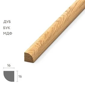
The current STAVROS product card confirms one profile dimension — 16×16 mm — and different commercial lengths depending on the material.
| Execution | Section | Product length | Sanding | For calculation |
|---|---|---|---|---|
| MDF | 16×16 mm | 2600 мм | «Prestige» | Separate cutting map |
| Beech | 16×16 mm | 2400 мм | «Prestige» | Separate cutting map |
| Oak | 16×16 mm | 2400 мм | «Prestige» | Separate cutting map |
For the current MDF version, the card also indicates preparation “for enamel.” The product itself can be checked at the link buy molding MLD‑038.
MLD‑038 cannot be treated as an ordinary flat slat that can be laid one on top of another without consequences. Despite identical dimensions of 16×16 mm, the profile has a decoratively formed three-dimensional cross-section. Therefore, in a cross-shaped junction, overlapping two strips changes the relief and thickness of the composition.




Why the 16×16 mm cross-section matters in the article
Not to retell the product card. It sets the scale of the junctions and preliminary arithmetic. If a horizontal line ends at the edge of a continuous vertical, each such point potentially reduces the nominal length of the horizontal segment by approximately the width of the occupied vertical zone — but the final dimensions are always taken from the approved junction, not derived by a single formula.
Our factory also produces:



Why 2400 and 2600 mm cannot be considered the same
The same set of finished parts fits differently into the source strips. The combination 1800 + 700 = 2500 mm fits into 2600 mm MDF, but does not fit into 2400 mm beech or oak. This means that after changing the material, a new cutting plan must be created.
Get Consultation
Why the current price should not be the core of the article
The price changes. A purchasing error in intersection junctions affects the number of whole strips more than a single temporary price per piece. Before ordering, the cost is checked in the product card; the article itself answers the question of how many and which parts are actually needed.
A drawing line is not yet the same as a finished part
On the layout, a vertical may run from the skirting to the upper edge of the panel. A horizontal crosses it in two or three places. In the drawing, these are two continuous lines. In the material, it is necessary to decide how they physically meet.
Various approved scenarios are possible:
- vertical continuous, horizontal divided into sections;
- horizontal continuous, vertical divided;
- both lines are interrupted and joined via a special carpentry joint;
- one line only visually "crosses" the other in the drawing, but in fact ends before it;
- the architect changes the drawing itself after the control sample.
The article does not designate one option as universally correct. The procurement task is to ensure that the designer selects one specific joint, and then translate it into parts.
Why the line axis and the part end are different coordinates
If on the drawing the horizontal runs from axis X1 to axis X4, and between them there are three continuous verticals, the finished horizontal parts may end at the boundaries of these verticals. This means the length of the centerline is not equal to the sum of the finished horizontal segments.
Why "let's add a 10% margin" does not fix the error
A margin can compensate for the missing linear meters, but it does not fix the incorrect length of each part. If 100 horizontal elements are calculated longer or shorter due to an incorrect joint, an extra strip in the warehouse does not turn them into correct parts without new cutting and rework.
Placing one MLD-038 on top of another — that creates a different relief
On paper, the cross looks flat. If two actual planks are simply laid one on top of the other, one of them will rise relative to the overall plane. The joint stops being the same grid as on the rest of the wall.
The consequences can vary:
- local protrusion;
- change in light and shadow;
- step at the intersection;
- different thickness of the decorative composition;
- complex visible end face;
- inconsistent result on repeating modules.
Why this question needs to be asked before ordering
After hundreds of meters of MLD‑038 have already been delivered and cut, discovering that the horizontals should have been split means recalculating almost the entire grid. The right question to ask before purchasing is:
"What exactly should the cross or T-joint look like in a real 16×16 mm profile?"
Why the purchaser should not invent the joinery detail themselves
They can flag the conflict and request a decision, but should not independently choose the overlap, rebate, trimming, or another joining method just for convenient cutting. The detail affects the appearance and must be approved by the project and the sample.
The joint map should appear before the meter schedule
A repeating grid usually has more than one type of joint. It is useful to introduce codes.
| Code | Node type | What needs to be defined | Impact on parts |
|---|---|---|---|
| J‑01 | Standard frame corner | Method of joining two sides | Vertical and horizontal lengths |
| U-02 | T-shaped junction | Which line is continuous | One line is split |
| U-03 | Cross intersection | Line priority / separate node | Multiple parts change at once |
| U-04 | Line termination | Exact endpoint | A separate short element appears |
| U-05 | Door junction | Decorative grid boundary | Non-standard module |
| U-06 | Skirting/profile junction | Vertical termination point | Separate finished length |
Why each distinct node is a separate row
If U‑02 near a standard vertical and U‑02 near a door have different dimensions or terminations, the same node name is no longer sufficient. Versions are needed: U‑02A, U‑02B.
What to record in the enlarged fragment
- scale;
- the axis of each line;
- the outer contour of MLD‑038;
- a continuous part;
- the ends of interrupted elements;
- finished dimensions;
- finish;
- version.
First one control module, then 50 identical walls
On a large project, the most dangerous action is to immediately multiply a beautiful scheme by the number of rooms. First you need one reference grid M-01.
The following sequence is performed for it:
- the external dimensions of the module are fixed;
- the axes of verticals and horizontals are drawn;
- U-01…U-06 are marked;
- continuous parts are assigned;
- broken lines are split into actual segments;
- finished lengths are taken;
- a control fragment is made;
- version M‑01/R01 is approved;
- only then is the module replicated.
What exactly the control fragment must prove
Not just “beautiful/not beautiful.” It must confirm:
- the actual appearance of the T-joint;
- the actual appearance of the cross joint;
- relief match;
- the finished dimensions of the parts;
- assembly sequence;
- the ability to reproduce the solution in series.
Why one photograph is not enough
A photograph captures the external result, but does not retain the dimensions of the parts. After approval, both a photo and the dimensional diagram M‑01 are needed.
Example: two horizontals intersect three verticals
Suppose one module has three verticals V1–V3 and two horizontals H1–H2. The design specifies that the verticals are continuous, and the horizontals approach them from both sides.
Number of nodes:
2 horizontals × 3 verticals = 6 intersections.
If the purchaser counted each horizontal as a single line from the left to the right edge, they would get two parts. In fact, each horizontal line is divided by the verticals into four sections:
- left edge;
- between V1 and V2;
- between V2 and V3;
- right edge.
Two horizontals yield:
4 sections × 2 = 8 horizontal parts.
Plus three vertical continuous parts.
In total, one module contains at least 11 main elements even before accounting for external frames and other assemblies.
Why this is fundamental for cutting
Instead of two long horizontals, eight short ones appear. They can effectively use offcuts after the verticals. But the number of end faces, labeling, and assembly completeness grows.
Why the module must be counted as a set
If one M‑01 requires V1–V3 and eight horizontal segments, the warehouse must be able to confirm the completeness of exactly this set, and not just issue “8.4 meters of MLD‑038.”
Conditional intersection arithmetic shows the scale of the error, but does not replace the assembly drawing
For a preliminary check, one can estimate how much simple addition of centerlines differs from the actual sum of segments.
Suppose:
- in one module there are 6 junctions of horizontals to continuous verticals;
- nominal profile width — 16 mm;
- the project confirmed that the horizontal part ends at the edge of the vertical part.
Then the conditional difference:
6 × 16 = 96 mm per module.
If there are 50 identical modules:
96 × 50 = 4800 mm = 4.8 m.
That is, a single system geometric correction at intersections can accumulate to several meters across the project.
Why this is not a ready-made production formula
16 mm is the overall profile dimension, but the actual end point depends on the cross-section shape and the approved joint. If the assembly provides for a different connection method, the actual length correction will be different. Therefore, 4.8 m is an indicator of the scale of the error, not a ready-made order line.
What this calculation is useful for
It quickly shows why the phrase "take the total linear meters from the drawing and add 10%" can be weaker than one correctly approved detail. Across a series of dozens of modules, a small node error becomes systemic.
A parts list is stronger than the line "MLD-038 — 450 m"
After M-01 is approved, a detailed parts list is needed.
| Code | Purpose | Finished length | Per module | Modules | Total parts |
|---|---|---|---|---|---|
| V-01 | Continuous vertical | According to the drawing | 3 | 50 | 150 |
| G-01 | Left horizontal section | According to the drawing | 2 | 50 | 100 |
| G-02 | Middle horizontal section | According to the drawing | 4 | 50 | 200 |
| G-03 | Right horizontal section | According to the drawing | 2 | 50 | 100 |
This table gives production the answer not only to "how many meters" but also to "how many parts of what length."
Why the part is the unit of control
If M-01 must contain three B-01 and eight horizontal elements, a shortage of one G-02 is immediately visible. When tracking only meters, the warehouse may have enough material but not have a complete set.
Why codes help with reordering
Request:
"Need 20 parts G-02"
stronger than the request:
"We need another 8 meters of MLD‑038."
In the first case, the purpose and finished length are clear; in the second, you need to reconstruct which parts of the grid are not covered.
MDF 2600 mm and solid wood 2400 mm need to be recalculated
Once all finished parts are determined, the material affects the cutting plan.
Suppose M‑01 contains:
- three verticals of 1780 mm;
- four horizontals of 720 mm;
- four horizontals of 540 mm.
Net linear meters of one module:
3×1.78 + 4×0.72 + 4×0.54 = 5.34 + 2.88 + 2.16 = 10.38 m.
MDF option 2600 mm
Combination:
1780 + 720 = 2500 mm.
It potentially fits into a single 2600 mm strip before accounting for the cut and technological allowance.
If such a combination is technologically confirmed, three verticals can "take" three horizontals of 720 mm each. Remaining:
- one horizontal 720;
- four of 540.
Next, new combinations can be sought, for example 720 + 540 + 540 = 1800 mm.
Option beech/oak 2400 mm
1780 + 720 = 2500 mm no longer fits.
A combination is possible:
1780 + 540 = 2320 mm.
This means the cutting structure changes. You cannot calculate MDF and then simply replace the material line in the order.
Why this is especially important on 50 modules
Even a difference of one strip per module results in 50 units per project. With expensive solid wood, this is already a significant commercial error.
Long verticals are laid out first
Any grid has parts with different length criticality.
Priority:
- the longest continuous verticals;
- long horizontal lines without intersections;
- medium sections;
- short elements between intersections;
- fillers and end pieces;
- reserve.
Why the short G-02 should not be the first to take a whole plank
If G-02 is 420 mm, it can be obtained from many offcuts. A 2350 mm vertical from a 2400 mm solid wood blank requires an almost whole plank. If short parts are cut first, there may later be enough total length, but not enough continuous lengths.
Example of a useful offcut
Vertical 1750 mm from a 2400 mm solid wood blank:
2400 − 1750 = 650 mm.
If there is a 620 mm horizontal, the offcut potentially covers it. This means the long part not only does not interfere with the short one, but also creates raw material for it.
Example of a useless offcut
A 2330 mm vertical leaves about 70 mm. In most modules, such an offcut does not cover a separate decorative part. The plank is effectively fully occupied by the long vertical.
50 identical modules are calculated using one reference M-01
There is no need to build 50 identical tables. Once M‑01 is approved, the following is fixed:
- node version;
- set of parts;
- the material;
- finishing;
- cutting map;
- number of source slats per module.
For example:
M‑01 / MLD‑038 / MDF / version P03 / 10.38 m of clean length / ___ whole slats by cutting plan.
If the site has 45 standard rooms:
M‑01 × 45.
Why exceptions should not be masked inside M-01
A room near a door, column, or built-in wardrobe may have a different grid. For it, the following are created:
- M‑01A — near the door;
- M‑01B — next to the column;
- M‑01C — shortened module.
This way the standard module remains truly standard.
How to count the number of modules
| Type | Quantity | Status | Cutout |
|---|---|---|---|
| M‑01 | 45 | Approved | Standard |
| M‑01A | 3 | Approved | Separate |
| M‑01B | 1 | In progress | Do not release |
| M-01V | 1 | Approved | Separate |
Until M-01B is approved, it is better not to include its material in the final cutting layout.
Doors, openings, sockets, and furniture change not the “meters” but the structure of the module
The article does not turn into a piece about electrical wiring or doors. These elements matter only because they can change the grid pattern.
Examples:
- a door breaks the horizontal line;
- a socket block requires shifting the vertical line;
- a built-in wardrobe covers two vertical lines;
- a portal reduces the width of the outer field;
- a column creates a new non-standard section.
If the horizontal line crosses a door
On the drawing, it should no longer be counted as a single line. Left and right parts appear, possibly of different lengths.
If the vertical is hidden behind the cabinet
It cannot be left in the total meterage "just in case" if the project clearly shows the absence of molding behind built-in furniture.
If the socket shifted the line
Only the affected module is recalculated, not the entire series. But it can no longer be issued as M‑01 without a version.
A single overall reserve percentage is worse than a reserve split by lengths and module types
The "clean meterage + 10%" scheme does not distinguish long verticals from short node elements. For the MLD‑038 grid, it is more useful to split the reserve by function.
- long continuous verticals — whole strips of sufficient length;
- long horizontals — a separate reserve if they are not covered by leftovers;
- short node parts — can be partially covered by usable leftovers;
- non-standard modules — own reserve;
- operational stock — remains after the project is handed over.
Why 20 short offcuts do not replace one vertical
Suppose the warehouse has accumulated 12 m of MLD‑038 in 300–700 mm offcuts. For a future 2280 mm vertical, this stock is useless. Therefore, meters without length structure give a false sense of coverage.
How to store the reserve
| Group | Whole 2400/2600 | 1800+ | 800–1799 | 300–799 |
|---|---|---|---|---|
| MLD‑038 / MDF / M‑01 | ___ | ___ | ___ | ___ |
| MLD‑038 / oak / M‑01 | ___ | ___ | ___ | ___ |
| MLD‑038 / MDF / M‑01A | ___ | ___ | ___ | ___ |
Why it is better not to dissolve the reserve of non-standard modules in the general stock
If M‑01A near the door contains a unique 2140 mm part, the overall short stock of M‑01 does not replace it. At least one whole plank or a corresponding long offcut must be available specifically for this scenario.
Material for the control module must be accounted for as a separate line
The reference grid also consumes MLD‑038. If its material is taken from the main batch and not recorded, the total requirement will be understated.
Useful line:
MLD‑038 / control module M‑01 / material ___ / planks ___.
What happens after the sample is approved
There are three options:
- the sample remains the reference and is not used for installation;
- the sample is dismantled, and suitable parts are returned to reserve;
- the control module becomes the first working section of the site.
Each option affects the remaining quantity differently.
Why a sample cannot automatically be considered part of a series
The control fragment may contain trial cuts, extra joints, or an experimental assembly. Even if the appearance is approved, some details may not match the final production map.
When a second control sample is needed
If the material changes from MDF to oak/beech, or if U‑02/U‑03 are made in a different way. A new material and a new assembly require separate verification before replication.
Packaging and floor-by-floor configuration must preserve the module type
The current MLD‑038 card specifies a rigid packaging frame: up to 31 MDF items or up to 15 solid wood items. The final number of packages is confirmed by the seller when placing the order, but for the project it is useful to understand the scale of logistics in advance.
Example: 150 MDF planks
If we use the maximum of 31 items per frame, mathematically at least the following will be required:
150 / 31 ≈ 4,84.
That is, at least 5 packaging units when fully filled. The actual packaging may differ — it is confirmed by the supplier.
Example: 60 solid wood planks
With a guideline of up to 15 items:
60 / 15 = 4 packaging units.
But if the batch is split between floors and module types, it may be logistically more convenient to have a larger number of partially filled packages with clear labeling.
Why packaging cannot be labeled only as "MLD-038"
If a project contains M-01, M-01A, and M-01B, the same plank may belong to different phases. On the new label, it is useful to write:
MLD-038 / MDF / M-01 / floor 2 / 12 modules.
And separately:
MLD-038 / MDF / M-01A / door areas / floor 2.
Acceptance should check not only the item code, but also the material and length
Bad:
"MLD-038 — 210 pcs., 210 arrived."
Good:
- MLD‑038 / MDF / 2600 — ___ pcs.;
- MLD‑038 / beech / 2400 — ___ pcs.;
- MLD‑038 / oak / 2400 — ___ pcs.
Why the total can be correct with an incorrect delivery
For example, an order:
- 150 MDF;
- 40 beech;
- 20 oak.
Total 210.
Actual:
- 145 MDF;
- 45 beech pieces;
- 20 oak.
The total of 210 matches, but MDF is short by 5, and beech arrived with a surplus of 5.
Why length must be checked against the line
Beech 2400 cannot automatically be considered a replacement for MDF 2600, even with the same cross-section. If M-01 contains long parts, the entire cutting plan may depend on 2600 mm.
What to do with packaging after repacking
If the material is divided by floors, the new bundle retains the SKU, material, length, and module type. Otherwise, after a few days at the site there will be unnamed 16×16 strips whose origin has to be guessed.
Cost must be calculated by whole strips and the standard module, not only by linear meter
The price per meter is convenient for comparison, but a wholesale batch is purchased in whole units. Therefore, the commercial model must include:
- number of MDF 2600 strips;
- number of beech 2400 strips;
- number of oak planks 2400;
- packaging;
- delivery;
- cutting/preparation of parts;
- finish;
- reserve;
- control module.
Cost of one standard module
After calculating the entire standard batch, it is useful to obtain:
cost of standard M‑01 / quantity of M‑01.
This way the customer understands the price of a repeatable solution, not just the total amount per floor.
Why the same square footage of MDF and oak does not mean the same project cost
The material differs in price, and 2600 and 2400 mm may require a different number of whole planks. You need to compare the final configuration, not the price of one conventional linear unit.
How to compare two supplier offers
Only on identical specifications:
- one material;
- same finished parts;
- one reserve;
- same packaging scheme;
- same finishing stage.
Otherwise, a lower price may hide a different order composition.
When it's too early to buy MLD-038 in bulk
It's better not to release a mass order if:
- the grille exists only in the visualization;
- the actual axes have not been approved;
- it has not been decided what U-02 and U-03 look like;
- no physical control fragment;
- standard and non-standard modules are not separated;
- the material may still change;
- the calculation exists only in linear meters;
- 2400 and 2600 mm are considered the same;
- long parts are not reserved;
- it is unclear what happens at doors, furniture, or columns.
When MLD-038 is better replaced with another profile
If the 16×16 mm volumetric section makes intersections too bulky, it may be more logical for the project to use a thinner profile or change the grid geometry. MLD‑038 should not be forced to work just because it has already been selected in the sketch.
When a flat decorative grid matters more than the item code
If the design requires a visually perfectly flat grid without pronounced relief at the joints, you must first confirm that MLD-038 can achieve this result with the selected connection. If not, another profile may be more appropriate.
Full calculation of 50 modules after approval of continuous verticals
Let's consider a conditional but fully traceable example. In one M-01:
- 3 continuous verticals of 1780 mm each;
- 2 horizontal levels;
- each horizontal level after three verticals is divided into four sections;
- lengths of horizontal sections: 520, 640, 640, and 520 mm.
For one level:
520 + 640 + 640 + 520 = 2320 mm.
For two levels:
2320 × 2 = 4640 mm.
Verticals:
1780 × 3 = 5340 mm.
Net length of one M-01:
5340 + 4640 = 9980 mm = 9.98 m.
For 50 identical modules:
9.98 × 50 = 499 m of net MLD-038.
But the line "499 m" is still not ready for ordering. It contains:
- 150 verticals of 1780 mm;
- 200 end horizontal sections of 520 mm;
- 200 middle sections of 640 mm;
- a total of 550 individual parts.
These 550 parts are exactly what needs to be distributed among the original strips.
MDF cutting 2600 mm
For the 1780 mm vertical, what remains is:
2600 − 1780 = 820 mm.
A 640 mm horizontal can potentially fit into this remainder. So one strong combination is:
1780 + 640 = 2420 mm.
After that, about 180 mm remains before accounting for the cut.
If 150 verticals are combined with 150 horizontals of 640 mm each, then 150 original strips cover:
- all 150 verticals;
- 150 of the 200 medium horizontal parts.
remains:
- 50 parts of 640 mm each;
- 200 parts of 520 mm each.
For the short group, a combination can be considered:
640 + 520 + 520 + 520 = 2200 mm.
About 400 mm remains before accounting for cuts. Or:
520 × 5 = 2600 mm
purely arithmetically, but five parts will require four cuts, so this scheme may not fit technologically. It cannot be asserted without accounting for kerf width and allowance.
Even in this simplified example it is clear: the actual number of strips is determined by combinations, not by dividing 499 / 2.6.
Cutting solid wood 2400 mm
Vertical 1780 + horizontal 640:
1780 + 640 = 2420 mm.
The combination no longer fits within 2400 mm. However:
1780 + 520 = 2300 mm.
This means the solid slab layout is built differently: it is rational to combine the verticals with the outermost horizontals of 520 mm.
If 150 verticals each get one 520 mm piece, the following are covered:
- 150 verticals;
- 150 out of 200 pieces of 520 mm.
Remaining:
- 50 pieces of 520 mm;
- 200 pieces of 640 mm.
A difference of only 200 mm in the original commercial length completely changes the "partner" for the long vertical and the structure of the short remainder.
Why is the total net linear meterage the same, but the procurement different?
Both MDF and oak/beech must cover the same 499 m of net parts. But the number of whole source strips, offcuts, and combinations will differ. Therefore, quotations for MDF and oak cannot be compared using a single conversion factor.
What happens if, after M-01 is approved, one intersection node changes
Suppose version R01 provided for continuous verticals. After the control fragment, the architect decides that on one of the horizontal levels a continuous horizontal should be made, and the verticals should be broken.
The overall external pattern is similar, but the parts list changes.
R01:
- 3 verticals of 1780 mm each;
- 8 horizontal sections.
R02:
- some verticals are split into upper and lower segments;
- one horizontal becomes a long continuous piece;
- the number of ends changes;
- the cutting map changes.
Why you can't keep the previous number of meters
The total net meterage may change slightly. But the length structure changes dramatically. Instead of four short horizontal parts, one long one appears, and several verticals turn into pairs of segments. The material is the same, the cutting is different.
How to format the version
| Module | Version | Main change | Status |
|---|---|---|---|
| M‑01 | R01 | Verticals are continuous | History / sample |
| M‑01 | R02 | One horizontal is continuous | Active |
If some rooms have already been installed according to R01, they remain in the history. A new batch for the remaining rooms is ordered according to R02. You cannot simply replace the file and forget where the previous version was.
The actual consumption of the first five modules must be compared with the calculated one
After starting a series, it is useful not to wait until the end of the floor. The first 3–5 M‑01 provide information about the quality of the calculation.
Let the design net consumption of one module be 9.98 m. For the first five rooms, the following was obtained:
| Module | Calculation | Actually installed | Useful return | Comment |
|---|---|---|---|---|
| 1 | 9.98 m | 10.14 m | 0.42 m | Additional short section |
| 2 | 9.98 m | 10.00 m | 0.55 m | Within the map |
| 3 | 9.98 m | 10.13 m | 0.38 m | Door node repeats |
| 4 | 9.98 m | 10.11 m | 0.49 m | The same node repeats |
| 5 | 9.98 m | 10.12 m | 0.44 m | Systematic discrepancy |
If almost every room gets an extra piece of roughly the same length, this is not "random overuse" but a master specification defect.
How the error scales
Suppose the unaccounted section is 140 mm per module.
For 50 modules:
0.14 × 50 = 7 m of pure material.
But the actual impact on the number of planks may be greater or smaller depending on whether these short pieces can be obtained from leftovers. Therefore, after a systematic error is detected, not only the linear meters but also the cutting plan are updated.
Returning leftovers from the first floors can significantly reduce the next queue
Suppose that after 20 modules of M-01, the following have accumulated in the warehouse:
- 6 whole MDF planks 2600;
- 10 remnants 900–1500 mm;
- 24 remnants 500–800 mm;
- many small offcuts shorter than 300 mm.
The next batch — another 20 modules.
Ordering the full volume for 20 new modules right away without accounting for remnants is wrong.
First, the list of future parts is compared against the remnant bank:
- long verticals are covered with whole strips;
- medium horizontals — with 900–1500 remnants;
- node pieces Г‑01/Г‑02 — with 500–800 remnants;
- unsuitable short offcuts are not counted as useful stock.
Only after this is the new order calculated.
Why “31 m left in stock” is not enough
31 m could be six whole planks and a good set of medium offcuts — a strong resource. Or it could be a hundred small pieces of 200–400 mm — an almost useless stock for a long grid. The length of each remnant matters more than the total sum.
A non-standard module near the door must be calculated in full, not by adding a coefficient
Suppose M‑01A near the door differs only by one vertical and two horizontals. There is a temptation to take M‑01 and add “5% for the door.”
It is more correct to issue a separate set:
- V‑01A — vertical next to the architrave;
- G‑01A — left horizontal;
- G‑02A — right horizontal;
- standard parts that actually match M‑01.
In this case, M-01A uses shared positions where they are identical, and separate ones only where the geometry has changed.
Why this is better than a full duplicate of the table
There is no need to copy the entire module again and create a risk of divergence between identical parts. M-01A can be stored as:
M-01 + replace B-03, G-02, and G-03 with versions A.
This is more convenient for revisions and reduces the number of independent rows.
The cross-shaped joint U-03 must be checked for light and shadow, not just for matching dimensions
Even if the joinery solution is geometrically precise, a 16×16 volumetric profile can create a noticeable local shadow at the cross. On a wall with 20–30 intersections, this effect becomes rhythmic.
The control fragment should be viewed:
- under frontal lighting;
- with side lighting;
- in the specified finish;
- from the distance at which the wall is usually perceived.
If a junction looks heavier than in the visualization, the right solution is to change the junction or profile before ordering, rather than trying to "hide" the effect with finishing after installation.
Why a new material requires a new junction sample
MDF under enamel and oak with a clear finish can both be 16×16 mm, but the light-and-shadow, the visibility of the end face, and the perception of the joint differ. A junction that looks calm in white enamel may read more strongly on natural oak.
Therefore, changing the material after M‑01 approval triggers a review of at least the key U‑02/U‑03 junctions.
Decision tree for each grid intersection
To avoid deciding each junction "by eye," it helps to use a short algorithm.
Step 1. Do two or more lines meet at the junction?
No → this is an ordinary continuous part or an end.
Yes → we move on.
Step 2. Does the project clearly show which line should be continuous?
Yes → keep the continuous line as a single part, split the second one along the approved boundaries.
No → the assembly cannot be released to production until the designer decides.
Step 3. Is there an approved method of physical connection?
Yes → finished lengths are taken from the assembly.
No → a control fragment is built.
Step 4. Is the assembly repeated?
Yes → it receives the code U‑02/U‑03 and is replicated.
No → it remains an individual part of a non-standard module.
Step 5. Has the material changed?
Yes → a new sample is checked and the 2400/2600 cutting layout is rebuilt.
No → the previous geometry can be used if the other conditions match.
Such an algorithm does not make the design decisions for the architect, but it prevents procurement from turning an unresolved cross into "just two moldings."
Example: 100 modules and one systemic error of 32 mm
Suppose M-01 has one T-joint that was mistakenly calculated as 32 mm longer than required by the approved junction.
On one module:
excess length = 32 mm.
On 100 modules:
32 × 100 = 3200 mm = 3.2 m.
But the real damage is not limited to 3.2 m. If each erroneous part has already been cut separately, the project has 100 parts of the wrong length. They cannot be "put back together" into three meters of the original profile. Some can be shortened if the error is on the larger side and the joint allows reworking; some may become waste. If the part turns out to be 32 mm shorter, all 100 elements require replacement.
This is why a systemic error in a serial module is more dangerous than a random error in the total meterage.
Example: an error in the smaller direction is not compensated by the reserve
Suppose 100 G‑02 horizontals are made 24 mm shorter.
Total deficit:
24 × 100 = 2400 mm.
The warehouse has two whole strips of 2600 mm — formally 5.2 m of reserve, more than the total deficit. But it is impossible to fix already finished parts by lengthening them. It is necessary to manufacture 100 new G‑02, which means the reserve is calculated based on the original strips for this series, and not on the sum of missing millimeters.
Why the cost of rework depends on the stage at which the error is detected
The same defect in an assembly has a different cost at different stages.
| Stage | What has already been done | What needs to be corrected | ||||||||||||||||||||||||||||||||||||||||||
|---|---|---|---|---|---|---|---|---|---|---|---|---|---|---|---|---|---|---|---|---|---|---|---|---|---|---|---|---|---|---|---|---|---|---|---|---|---|---|---|---|---|---|---|---|
Д
How the supplier should see the order, and the site — the distributionA commercial specification can be provided to the supplier:
Within the object, the same batch is broken down:
This way, the seller does not have to understand every interior assembly, and the object does not lose the origin of the quantity. How to estimate the minimum number of packaging units without promising exact logisticsThe card indicates up to 31 MDF items and up to 15 solid wood items in a rigid packaging frame. This allows only a preliminary estimate. For example, an order of 186 MDF slats: 186 / 31 = 6. The minimum is 6 fully filled frames. But if 186 slats need to be divided between three floors of 62 pieces each, it may be logistically more convenient to use a larger number of partially filled packages with floor-by-floor labeling. The final format is confirmed by STAVROS at checkout. For 47 oak slats: 47 / 15 ≈ 3,13. That is, mathematically no fewer than 4 packaging units under the current limit of "up to 15". This figure helps plan space on site, but does not replace the actual packing list. Reverse audit after summing up the entire orderWhen all modules are combined into a single order, you need to work the number backward. Suppose the final line is: MLD‑038 / MDF / 2600 — 212 slats. It should be disclosed in:
If 212 strips cannot be traced back to clear sources, the order contains either double counting or an undocumented stock. What to hand over to operations after the project is completedIf the wall grille is part of a permanent interior, it is useful to leave the following for the operations service:
Then local repair after a few years begins with the exact part G‑02 or V‑01, rather than with an attempt to restore the intersection pattern by eye. 15 mistakes that turn a serial grille into a wrong sort and rework1. Add up all the lines of the drawing and call it the order's linear footageWhy it occurs: axial lines are easy to measure in the project. Consequence: gaps at intersections are not taken into account, and the finished parts remain unknown. How to prevent it: first a joint map and a parts list. 2. Count two intersecting lines as two whole partsCause: in the drawing, a cross looks like two continuous strips. Consequence: in the actual profile, an overlap, a step, or another unforeseen relief occurs. Prevention: U‑03 is approved physically before replication. 3. Make the vertical continuous without the designer's decisionCause: the vertical seems "more important." Consequence: the purchaser effectively changes the architectural assembly. Prevention: the line priority is fixed in the reference drawing. 4. Use one assembly for a T-junction and a crossCause: both scenarios are perceived as an "intersection." Consequence: different parts get the same lengths and markings. Prevention: separate U‑02 and U‑03. 5. Treat 16 mm as a ready-made correction for each intersectionCause: the profile has an overall dimension of 16×16. Consequence: preliminary arithmetic turns into a production dimension without accounting for the actual assembly. Prevention: use 16 mm only for scale estimation, and take final lengths from the approved drawing. 6. Immediately multiply the sketch by 50 roomsCause: the rooms are standard. Consequence: one assembly error is repeated 50 times. Prevention: first M‑01 and a physical fragment. 7. Do not designate M-01A near the doorCause: there is a desire to keep a single standard schedule. Consequence: the door horizontals and end verticals end up with incorrect lengths. Prevention: exceptions get separate codes. 8. Recalculate MDF and then simply replace it with oakCause: the cross-section is the same. Consequence: 2600 mm becomes 2400 mm, and part combinations no longer fit. Prevention: a new cutting plan for each material. 9. Cut short parts before long onesCause: they are easier and faster to produce. Consequence: solid strips disappear, and for verticals of 2300–2350 mm only short leftovers remain. Prevention: prioritize length. 10. Add 10% and do not build a cutting planCause: the usual estimating approach. Consequence: there is stock in meters, but not the required lengths. Prevention: reserve after the parts list and cutting plan. 11. Do not account for the material of the control moduleCause: the sample is assumed to be part of the project as a matter of course. Consequence: several strips disappear from the main batch. Prevention: a separate line for the M‑01 sample. 12. Accept a mixed delivery only by the total quantityCause: everything is called MLD‑038. Consequence: MDF and solid wood may be mixed up even when the total is correct. Prevention: line-by-line acceptance by material and length. 13. Mark by floor onlyCause: it seems the installers will figure it out from the drawing. Consequence: M‑01A parts end up on a regular M‑01 wall. Prevention: module and zone on the packaging. 14. Do not return usable offcuts to inventoryCause: offcuts stay with the crew. Consequence: the next queue buys new planks, even though short junction parts could be covered by offcuts. Prevention: return by length ranges. 15. Change the opening size without recalculating the linked moduleCause: the total wall footage has barely changed. Consequence: short horizontals near the door no longer match the actual geometry. Prevention: any geometric revision triggers recalculation of only the affected module. Checklist, marking, and a ready supplier requestChecklist before payment
How to mark a standard batchExample: MLD‑038 / MDF / 2600 / M‑01 / floor 2 / modules 12 / R03. For a non-standard zone: MLD‑038 / MDF / 2600 / M‑01A / door / floor 2 / R02. For solid wood: MLD‑038 / OAK / 2400 / M‑01 / office / T‑01. Ready supplier requestWorking format: “Please calculate a batch of MLD‑038 molding for a repeating wall layout. Material — according to the attached specification. Cross-section 16×16 mm. The quantity of whole commercial strips is determined after approval of the reference module and cutting maps. Standard modules and non-standard zones are listed separately. The reserve is indicated as a separate line. Please confirm the current price, availability or production time, packaging, and delivery terms.” What to attach to the request
How to use product and broad commercial linksFor a specific product, anchors are useful MLD‑038 16×16 mm и wooden molding MLD‑038. The same card does not need to be linked at every mention. There is already material for profile comparison MLD‑027 or MLD‑038. The new page does not repeat the choice between them. There is a separate scenario MLD‑038 through the corner of the cabinet; it is dedicated to the facade and side panel, not to the standard wall grid. General wholesale anchorsIf the order is placed as building materials Moscow wholesale, via finishing material suppliers, building material suppliers, Construction material suppliers Moscow, Wholesale building material suppliers, wholesale building material suppliers or Building materials suppliers wholesale, MLD‑038 still remains a separate technical specification. The same rule applies to wholesale purchase of building materials, wholesale purchase of building materials, building materials at wholesale prices, buy finishing materials wholesale, finishing materials wholesale, wholesale supplies of building materials и delivery of finishing materials. The general contract must not turn M‑01, M‑01A, and different materials into a single line. Final algorithm and answers to questions before a wholesale orderFinal algorithmCONFIRM MLD‑038 → FIX 16×16 MM → SEPARATE MDF 2600 AND SOLID WOOD 2400 → APPLY ALL VERTICALS AND HORIZONTALS → CODE U‑01…U‑06 → APPROVE WHICH LINE IS CONTINUOUS IN U‑02/U‑03 → ASSEMBLE M‑01 → OBTAIN FINISHED PARTS → IDENTIFY M‑01A/B/C → LAY OUT LONG ELEMENTS FIRST → USE REMAINDERS FOR SHORT ASSEMBLY PARTS → BUILD SEPARATE MAPS FOR 2600 AND 2400 → COUNT WHOLE STRIPS → ACCOUNT FOR THE CONTROL MODULE → ADD A SEPARATE RESERVE → MARK BY MODULES AND FLOORS → ACCEPT DELIVERY LINE BY LINE → ACCOUNT FOR RETURNS → REORDER BY SPECIFIC PARTS AND FINISHES. Can I simply count all the axial lines and buy that linear footage?For a preliminary budget — yes. For the final order — no. At intersections, the line may split into several parts, so a detail drawing is needed first. Which line should be continuous — vertical or horizontal?There is no universal rule. It is an architectural and joinery decision for a specific composition. It is approved on a control sample. Can one MLD-038 be layered over another in a cross?Only if that exact relief is approved by the project. Simple layering changes the plane and the light-and-shadow of the detail. Should 16 mm be subtracted at each intersection?No, not as a universal production dimension. 16 mm can be used for a preliminary scale estimate, but final lengths are derived from the approved detail drawing. Can I check M-01 once and multiply it across all rooms?Only for truly identical rooms. Doors, columns, furniture, and other changes create versions M‑01A/B/C. Why do MDF and oak need to be recalculated?Because the original lengths of 2600 and 2400 mm produce different combinations of parts and a different number of whole planks. Can MDF leftovers be used for the oak group?No. The material and finish are different. Leftovers work only within a fully compatible product group. When is it not enough to calculate the reserve in meters?Almost always, if there are long continuous elements. For repairs, the length of the specific leftover matters, not just the total. Should the reference sample be included in the total volume?Yes, as a separate line. After approval, decide whether it remains a reference, goes into installation, or partially returns to the reserve. When is it too early to buy MLD-038?If U‑02/U‑03 have not been approved, there is no reference module, the material may change, or the calculation exists only in linear meters. Before final payment, it is useful to perform a final two-way reconciliation. From each order line, you need to trace back to the specific modules and parts that formed it; from each M-01, M-01A, and custom assembly — back to the original strips of the required material and length. If some strips cannot be explained by specific parts, an undescribed reserve remains in the specification. If an individual part exists in the bill of materials but no suitable original length is reserved for it, the object is not yet supplied with material. Such a check is especially useful after several revisions, when the same grille already has different versions on different floors. For a serial object, this provides another advantage: during local repair or modification of a single wall, there is no need to re-measure the entire grille. It is enough to determine the module code, assembly version, and specific parts, then use the saved cutting plan and remnants of the required length. This way, the system remains manageable for any subsequent phase of the object. After such preparation, buying molding MLD-038 wholesale means ordering not “450 meters of 16×16 profile,” but an exact set of continuous verticals, interrupted horizontals, special assemblies, and standard modules converted into real parts, whole strips of 2400/2600 mm, packaging, reserve, and a reproducible reorder. |