Article Contents:
- A single project item must retain its identity
- The architectural system is defined at the concept stage
- What must be defined at each stage
- Real products are selected before the final visualization
- The 3D model must match the physical product
- A selection made from a visualization is documented as a specific entry
- A sample and trial coating verify the physical result
- Approval confirms the product, finish, and conditions of use
- DWG transfers the selected stucco to working geometry
- Individual nodes link stucco with other works
- The specification must uniquely identify the product
- The calculated footage and the number of strips differ
- Piece decor, mirror pairs and sets are counted separately
- Document revisions must be consistent with each other
- Replacing the item code returns the position to the affected checks
- Purchasing is carried out based on ready-made positions and confirmed conditions
- Acceptance compares the delivery with the order and the sample
- Installation receives a completed design solution
- The readiness table shows that ordering is possible

Replacing a 35 mm wide moulding with a 22 mm profile will increase the inner field of the frame by 26 mm while keeping its outer size unchanged. At the same time, the relief, light and shadow, and the joints with the decorative corners will change. If only the line in the order is replaced, the working drawing and the approved visualization will continue to describe the previous composition.
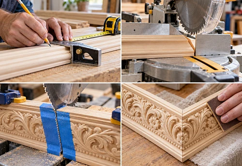
Therefore, stucco for a design project requires consistent recording of decisions. First, its role in the interior is determined, then actual products are selected, the appearance and finish are agreed, drawings are issued, and the quantity is calculated. When moving between stages, the link to a specific article must be preserved. Then the selected Polyurethane moldings reaches the site in the composition specified by the project.
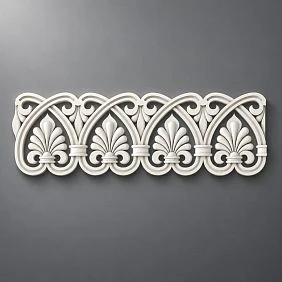
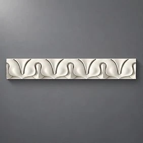
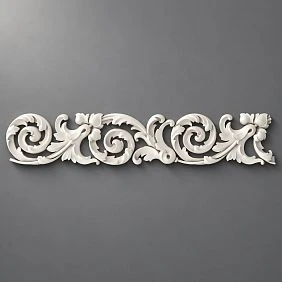
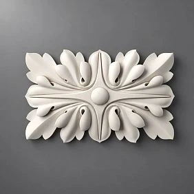
A single project item must retain its identity
The designation M-01 is convenient to use for the main wall moulding throughout the project: in the 3D scene, on the elevations, in the specification, and in the order. By itself, it does not yet define the product. The manufacturer, article, material, size version, and finish are linked to it.
At the comparison stage, M-01 may have several candidates. After approval, one selected option remains. If it has to be changed, the history is preserved: which product was accepted earlier, why the replacement appeared, and which documents were updated.
A common list of items helps avoid discrepancies between project participants. The visualizer does not take a random model from their collection, the specifier does not choose a similar strip from a photo, and the installer receives designations that match the delivery.
If the same profile is used with different finishes, this is also reflected in the designations. For example, M-01.1 and M-01.2 may have the same article but different colors. The quantity of material may be combined for purchasing blanks, but the distribution by finish and room must be preserved.




At the concept stage, the architectural system is determined
At an early stage, decisions are made about where frames, cornices, skirting boards, ceiling roses, or large panels are needed. The layouts may still be approximate, but the position of significant elements is already tied to doors, windows, furniture, and lighting.
For example, a large ceiling rose affects the ceiling layout and the position of the light fixture. A tall wall composition is tied to the top of the doors and the cornice. It is risky to leave such decisions until the ordering stage: by that time, related work may already have been completed.
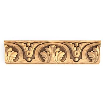
For the initial selection of a system, it is useful to consider Wall Decor complete compositions. This makes it possible to determine the density of the pattern and the relationship between long linear elements and individual pieces.
Exact product codes are not mandatory at the first meeting. However, constraints should be recorded immediately: the expected size range, the projection from the wall, placement zones, and the type of finish. If the opening has already been manufactured or the cabinet has been ordered, their actual dimensions become the initial data rather than conditional values that can be freely changed for the sake of the moulding.
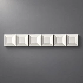
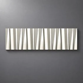
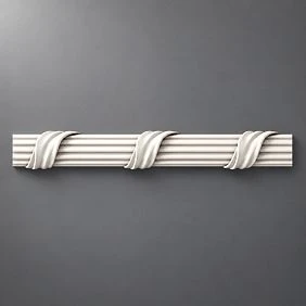
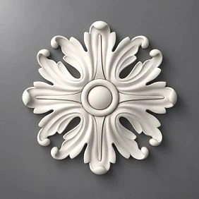
Our factory also produces:
What must be defined at each stage
It is convenient to divide the project into sequential levels of readiness. At each level, a new result appears that can be checked and passed on to the next participant in the work.
| Stage | What is recorded | Basis for moving forward |
|---|---|---|
| Concept | Types of decor, zones, axes, approximate scale | Approved architectural scheme |
| Selection | Real candidates, dimensions, material, links | List of compared products |
| Visualization | Specific models at real scale | Selected composition option |
| Sample | Relief, surface, preparation and coating | Sample approval record |
| Working drawings | Geometry, references, sections, details | Verified work kit |
| Specification | Products, versions, units, quantity | Approved statement |
| Procurement | Number of product units, delivery, current revision | Confirmed order composition |
| Installation | Received parts, layout, sequence | Working set handed over to the contractor |
This is the proposed workflow, which is adapted to the project. Stages may partially run in parallel: preliminary assemblies are useful to check during selection as well. But the result of the next stage must not conceal an unresolved issue from the previous one. An approved image, for example, does not automatically mean that the finish and installation feasibility have been checked.
Get Consultation
Before the final visualization, real products are selected
For the main item, a few meaningful candidates are usually enough. They are selected based on the task: line width, depth, section pattern, compatible decor, and available sizes. A long list without comparison criteria only shifts the choice to a later stage.
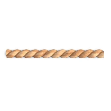
Let's consider two STAVROS products: MLDPU-002 measuring 22 × 11 × 2600 mm и MLDPU-003, size 35 × 12 × 2600 mmBoth are made of polyurethane but differ in width and profile geometry. These are real alternatives for comparison, not a single conventional molding shown at two scales.
The candidate list retains a link to the product card and the date the specifications were verified. If an item has multiple size options, the selected variant is recorded in full. The catalog section name does not replace material information: a single interior decor system may combine products made from different materials.
A candidate remains a candidate until it passes the checks required for the project. Its presence in the scene does not yet authorize purchase.
The 3D model must match the physical product
In the STAVROS section “Catalogues and drawings” design materials are available, including 3D models and DWG files. After downloading, verify the item code, units of measurement, and actual model dimensions. An import error can change the scale even without intentional editing.
Profile MLDPU-003 with a 35 × 12 mm cross-section must retain this cross-section in the scene. If it is stretched to 50 × 8 mm, the result is a different geometry that the original item no longer corresponds to. A new size requires a different real product or separately agreed custom manufacturing with confirmed capabilities.
The length of a straight molding in a composition is set by layout and trimming while preserving the cross-section. When working with ornament, the repeating pattern along the strip must also not be stretched arbitrarily: the shape of the motifs changes.
Candidates are compared with the same camera, lighting, color, and furniture position. Then the difference between the images is explained by the profile itself. In addition to a close-up, a general view is needed: an expressive detail up close may almost disappear on a large wall or, conversely, make the layout overly busy.
A choice made from a visualization is documented as a specific entry
The phrase “we’ll keep the second option” quickly loses meaning if new images appear or the file order changes. The result of the review is better recorded via the project position and product: “M-01, STAVROS, MLDPU-003, 35 × 12 × 2600 mm, selected from visualization.”
It is separately noted what still needs to be checked. For example, the appearance has been agreed, but a coating sample and a solution for the junction with the architrave are still expected. Such a record allows work to continue without creating the impression that the item is fully ready.
A specific version of the visualization is linked to the selected product. If later only the wall color was changed, this must be distinguished from replacing the profile itself. In the first case, the geometry may remain the same; in the second, additional verification of the drawings and quantities will be required.
It is useful for project participants to designate in advance the person responsible for recording decisions. An approval that remains only in one specialist's private correspondence does not become common baseline data for procurement and installation.
A sample and trial painting verify the material result
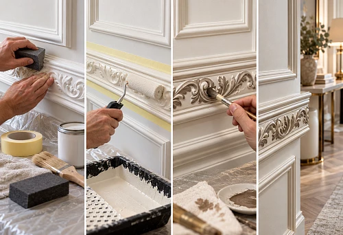
A physical sample shows the size of the relief, the character of the edge, and the surface of the product under real lighting. For wall stucco to be painted, the entire finishing system is also important: preparation, primer, paint, and degree of gloss.
In the section samples and catalogs materials can be selected to become acquainted with the products. At the same time, the composition and the possibility of obtaining the required fragment are clarified separately. A small section of profile does not replace a whole overlay if its full pattern needs to be assessed.
For a critical junction, a representative fragment is assembled: molding, corner, base, and the intended coating. It is checked under lighting close to the project lighting. If the parts will be painted together with the wall, the sample must reflect exactly this sequence of preparation and finishing.
The approved sample indicates the project item, article number, coating system, and date. It is useful to keep it until the work is completed. A photograph supplements the record, but color on a screen is not a reliable substitute for a physical reference. A sample of a different profile confirms only those properties that can actually be verified on it.
Approval confirms the product, finish, and conditions of use
The scope of the "approved" status must be clear. For M-01, this may mean that the product, cross-section, location, coating, and key junctions have been agreed. If only the profile shape has been checked, such a record cannot be interpreted as approval of the entire installation system.
The approval is recorded with the date and the responsible participants. A link to the sample and the current revision of the project data is stored alongside. This is especially useful when the client approves the appearance, the designer checks the junctions, and the kit assembler is responsible for the delivery contents.
After the decision is made, changes remain possible. However, replacing the profile, coating, or base goes through a check of the affected parameters. Repainting in a different shade does not always require a new cutting plan; switching to a wider molding can change the inner fields and junctions.
This procedure helps correlate the amount of rework with the actual change. The reason for the adjustment is recorded next to the result so that the previous decision does not return to the order from an old file.
DWG transfers the selected stucco molding into the working geometry
On the elevations and sections, the same article and size version are used as approved for the visualization. The width, depth, and length of the supplied strip, the cross-section shape, and the mounting plane are checked. A matching overall silhouette is not enough.
The designations A, B, C, and L are read from the drawing of the specific product. Size C may describe the maximum thickness or the overall depth dimension; it does not show the depth of each recess of the ornament. For spatial junction, the cross-section itself must be visible.
Frame dimensions are tied to the selected contour: outer, inner, or centerline. If on one sheet the width is indicated along the outer edges, and on another along the molding centerlines, the same numbers will produce different parts.
Before releasing the working drawings, the finished dimensions of the room and the state of adjacent solutions are verified. The planned panel thickness cannot be imperceptibly replaced with the actual one already during installation: the molding located on it will get a different projection relative to the door casing, baseboard, and neighboring elements.
Individual junctions connect the stucco molding with other works
The general view of the wall rarely accommodates all the information about the connections. A separate junction is needed where different execution methods are possible: next to the door casing, on the outer corner, at a niche, at the transition to a panel or built-in furniture.
For a corner overlay, the junction point with the straight moulding is shown. The overall dimension of the part does not always equal the length of the section that should be removed from the straight side of the frame. Selection decoration for moldings helps find the matching products, and the drawing clarifies their connection.
When using a flexible version, verify that it exists for the selected item, the permissible bending direction, and the radius limits. The properties of one flexible part cannot be automatically transferred to another article or to a standard rigid strip.
A ceiling medallion requires coordination with the light fixture and the ceiling structure. The decorative element does not replace the fixture's attachment to a suitable base. At the assembly, the medallion position, the cup installation, and the equipment fastening are separated. Before purchase, it must be clear who is responsible for each part of the assembly.
The specification must unambiguously identify the product
The name “wide white moulding” describes the appearance but does not allow ordering a specific product. The specification of decorative elements needs data by which another person can verify the supplier's offer without guessing.
Below is an example of filling in an item for a hypothetical project with four identical frames. The quantities given apply only to this calculation example.
| Field | Value |
|---|---|
| Project item | M-01 |
| Manufacturer | STAVROS |
| Article number | MLDPU-003 |
| Purpose | Main moulding of four wall frames |
| Dimensions | 35 × 12 × 2600 mm |
| Material | Polyurethane |
| Finishing | Per approved sample O-01; painted on site |
| Trade unit | Plank 2600 mm long |
| Estimated requirement | 24.8 linear meters in pre-cut lengths |
| According to the cutting map | 12 planks |
| Separate reserve | 1 plank taken as an example |
| To order | 13 planks |
| Source of specifications | MLDPU-003 product card |
| Related documents | Wall elevation, details, and cutting map of the current revision |
In a real specification, the finish is described through a sample entry: the specific coating and preparation. A current product link, item status, and related sheet numbers are placed alongside. A single product image is not sufficient for identification.
The calculated linear meters and the number of planks differ
For four frames with an outer size of 1000 × 2100 mm, eight sides of 2100 mm and eight of 1000 mm are required. We use solid sides with 45° miters; the cut lengths are given along the long outer edges.
The total length is 24.8 m. Dividing by 2.6 m with rounding up gives ten planks, but this quantity will not be enough under the accepted condition of solid sides.
| Parts group | Requirement | Placement on a 2600 mm bar | Planks |
|---|---|---|---|
| Vertical sides | 8 × 2100 mm | On one side | 8 |
| Horizontal sides | 8 × 1000 mm | On two sides | 4 |
| Total by cutting plan | 24.8 m of finished segments | Taking into account the accepted division | 12 |
| Separate reserve | 1 whole plank | Not included in working segments | 1 |
| Order | 33.8 m in commercial strips | 13 × 2600 mm | 13 |
The map additionally accounts for the saw kerf, end trimming and profile direction. In this example, gaps remain between the sum of the part lengths and the length of each blank, allowing these operations to be provided for.
Offcuts from cutting and the reserve serve different purposes. A piece of about 500 mm will not replace a damaged side 2100 mm long. Therefore, the percentage added to the total footage does not replace checking the required lengths and making a separate decision about spare strips.
Piece decor, mirrored pairs and sets are counted separately
Decorative Inserts are accounted for by article numbers and finish. If each of the four panels includes one mirrored pair, four left-hand and four right-hand parts will be required. An entry of “four overlays” will halve the order.
for the ceiling rosette the product unit is clarified: a single item, a set or a composition of separate elements. The number of rosettes in the interior and the number of parts in the delivery may differ. The composition is checked against the selected product page and the order confirmation.
For a ready-made set, it is important to establish which mouldings and overlays are already included. Otherwise, identical items will appear in the schedule twice — within the set and as separate lines.
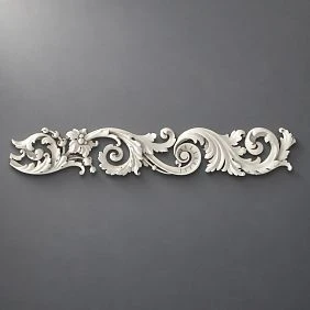
for ornamental trim cutting is additionally linked to the pattern: the position of motifs, joints and endings. Its requirement cannot be calculated without checking according to the rules for a smooth strip of the same length.
Document revisions must be consistent with one another
Before ordering, the composition of the current set is recorded: which versions of the unfoldings, assemblies, specifications and cutting layouts are used together. The date the file was last saved does not by itself confirm that the data are consistent.
Different documents may have different revision numbers. For example, the unfolding was changed three times, while the schedule was changed once. This is acceptable if the latest edit concerned only a signature or another area and did not affect the order. What matters is not whether the letters match, but whether the decisions contained in the documents correspond.
In the change log, it is useful to record the position, the reason for the edit, the affected sheets, and whether recalculation is needed. Moving the frame without changing dimensions may not change the amount of moulding, but it requires a new installation reference. Adding a second frame changes the drawing, the cutting plan, and the order.
Old revisions are kept for history but excluded from the active set folder. Recipients of the documents must receive a clear message about which sheets have been replaced. Names like "final new last" do not show the composition of the approved decision.
Replacing the item code returns the position to the affected checks
If the selected product is not available by the required date, first consider postponing delivery, splitting the order, or choosing another product. Confirming a replacement based only on a similar photo is not sufficient.
Suppose MLDPU-002 is proposed instead of MLDPU-003. With an outer frame width of 1000 mm, the free field will change from 930 to 956 mm. The difference arises from the profile being reduced by 13 mm on each side. The maximum depth dimension will also change from 12 to 11 mm, and the relief geometry will be different.
Re-check the frame type, joints with overlays, references, finish, and cutting plan. Keeping the outer dimensions sometimes allows the lengths of the straight sides to remain the same, but switching to different corner elements can change them. This is determined from the updated assembly detail.
If the order has already been placed, the change is additionally agreed with the supplier: whether the composition can be adjusted and which items have already been prepared. The new item code becomes effective only after the decision is recorded in all affected documents.
Purchasing is carried out based on ready items and confirmed terms
When polyurethane mouldings need to be purchased, the order assembler passes the supplier the specific item codes, versions, and number of product units. Project images help clarify the task but do not replace the request.
Before confirming the order, verify the material, size, left or right version, kit composition, finish on delivery, and actual delivery terms. Availability and lead time are checked for the specific quantity: the product page data does not mean that the entire required batch is already ready for shipment.
The received proposal is compared with the bill of quantities line by line. Units are checked with particular care: the price per strip, piece or set must refer to the same volume calculated in the project. Packaging, delivery and the distribution of the supply across stages are clarified separately. If the customer approved the budget before the final cutting plan, the amount is recalculated by product units. An increase in the order from ten conventional strips to twelve per the cutting plan plus one spare must be visible before payment.
An independent finished item can be purchased earlier than the others. However, ordering the main moulding early is risky if its lengths depend on decorative corners that have not yet been selected. Related products are best considered together.
To discuss a project with STAVROS, it is convenient to use the information from the section for designers and architects. The request is accompanied by a bill of quantities, characteristic details and a list of open questions. The request "order stucco for the project" becomes specific when it is clear which decisions have been approved and what exactly needs to be clarified.
Acceptance compares the delivery with the order and the sample
On site, item codes, dimensional versions, quantity, mirrored variants and completeness are checked. Long strips and thin protruding parts are inspected for damage. Any discrepancies identified are recorded before the parts are passed to cutting.
Comparison with the sample is carried out taking into account the finishing stage. If the approved fragment is painted and the batch is supplied for on-site painting, a colour mismatch in the blanks does not yet indicate that the goods have been substituted. First, the geometry, material and condition of the delivery are checked, then the agreed coating on a working sample.
Packages are conveniently marked with project item numbers and rooms while retaining the factory designations. The reserve is kept separate from parts already allocated to work. For staged delivery, a balance is kept for each item: ordered, received, handed over for installation, remaining.
A damaged long element cannot automatically be considered usable simply because most of the strip has survived. Its usefulness is determined by the specific segments of the cutting plan; otherwise the defect will be discovered after frame assembly begins.
Installation receives a completed project solution
The contractor receives the current elevation drawings, detail assemblies, cutting plan and information on the approved finish. The drawings must include original elevations, axes, dimensions of free margins and clear line terminations.
Before mass cutting, the actual geometry of a representative area is checked. A wall deviation, a changed panel thickness or a differently installed architrave may require adjustment. If the discrepancy affects the composition or the number of parts, the decision is returned to the project author and recorded before work continues.
The installation sequence is coordinated with adjacent contractors: furniture makers, ceiling, lighting and painting specialists. Decorative mouldings must not block the necessary access to equipment or interfere with the movement of doors and fronts.
It is useful to accept the representative first area before repeating the same solution throughout the entire site. The position of the profile, junctions, appearance of joints and finish are checked. The approved fragment links the working documents to the actual execution and provides a reference for the remaining areas.
The readiness table shows what can be ordered
A short table helps to see the remaining questions for each item. It is better to indicate a specific status than to put identical "ready" marks at different stages. Below is a conditional example unrelated to a real delivery.
| Position | Visualization | Sample | Drawings and detail assemblies | Specification and cutting plan | Purchase decision |
|---|---|---|---|---|---|
| M-01, main moulding | APPROVED | Approved | Checked | 13 strips to order | You can submit a request |
| K-01, cornice | Option selected | Coating being checked | Junction with niche open | Preliminary | Complete node and approval |
| R-01, rosette | APPROVED | Approved | Light fixture mounting checked | Completeness confirmed | Confirm supply |
Before ordering, discrepancies that change the result itself must be resolved: an unknown product code, an arbitrarily scaled model, a different profile in the drawing, undivided mirrored parts, a linear footage without cutting layout, or an unapproved substitution. For each open item, the next step and the responsible person are assigned.
A completed request for stucco decor contains a verifiable link between the selected product, its place in the interior, and the quantity to be supplied. It can be used to buy the stucco, accept it on site, and carry out installation without re-selecting the profile at every stage.