Article Contents:
- 1. A custom solution begins with the wall's purpose
- 2. Outline the available surface after furniture and doors
- 3. Choose the line pattern while keeping a single profile
- 4. Nested frames: account for the space between edges
- 5. Two moldings side by side can form a complex contour
- 6. Select real widths and relief for the chosen scheme
- 7. Justify the symmetry or offset of the composition
- 8. Around a door, design both the lines and the endings
- 9. Add the ornament to the already defined field
- 10. Color and light change the number of visible lines
- 11. Check the curved section before approving the design
- 12. Check four different views in the 3D model
- 13. Convert the design into a cutting layout and nodes
- 14. Assemble a test fragment with the finish
- 15. When a custom profile is needed
- 16. Assign the composition to specific products
- 17. Account for both contours and cut each SKU separately
- 18. How to take a custom layout through to ordering and installation
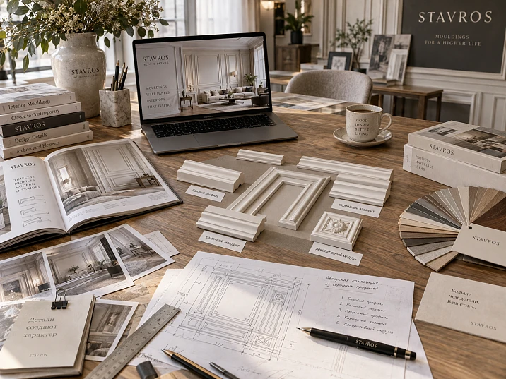
A double frame has a dimension that is easy to lose in a beautiful rendering: the free strip between the two contours. If you measure it between the axes of the moldings but install it between the edges, the inner field will turn out different. Along with it, the position of the panel, the proportions of the framing, and the lengths of the blanks will change.
Such relationships determine the result of working with ready-made decor. A single stock profile allows you to assemble a calm, large frame, a row of vertical fields, or a complex nested composition. This does not require changing the product itself — you need to design its position on the wall.
The designer moldings in this article are real catalog products used in custom layouts. We will look at how to move from a compositional idea to dimensions, a proven sample, and an order while preserving the intended pattern.
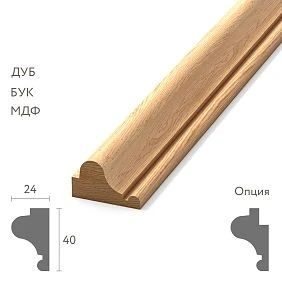
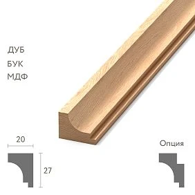
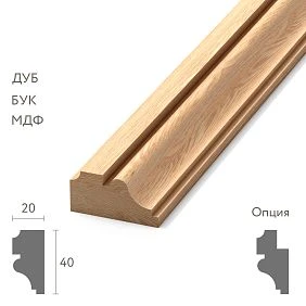
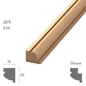
1. A custom solution begins with the wall's task
Determine what the composition should do: highlight a panel, connect a door with the adjacent wall section, frame a headboard, or organize a long empty surface. This determines whether you need closed frames, repeating verticals, or a single horizontal line.
The word “designer” itself does not define the material, cross-section, or method of production. A polyurethane molding from a stock catalog can participate in a custom project just as a specially developed element can. The difference lies in the available geometry and in how it is used.
Before developing a new profile, check the capabilities of ready-made products. Sometimes it is enough to change the ratio of the frames, add a second contour, or finish the line differently. But first, formulate what effect is missing: a wider framing, a smaller projection, a different pattern, or a specific junction.
This is not a promise of exceptional uniqueness for any layout. Custom work manifests itself in the connection between the decor and a specific room. If the composition can be transferred unchanged to any wall, it is useful to recheck its relationship to the architecture and furniture.




2. Outline the available surface after furniture and doors
On the elevation, first mark the door unit with casings, built-in furniture, baseboard, cornice, outlets, switches, and light fixtures. Separately show the items that will cover part of the wall: sofa, bed, console, TV.
The boundary of the decorative field does not always coincide with the boundary of the room. A wardrobe may occupy the left part of the wall, and then the center of the free area will be to the right of the overall center. It is the free field, not the entire architectural dimension, that becomes the starting point for the layout.
Clarify which items are fixed by the design and which can be moved. A composition precisely tied to a small console will lose its base after it is replaced with a long cabinet. For flexible arrangement, it is better to check several permissible furniture positions in advance.
Look at the wall from the doorway and from the main spots in the room. The top of the frame may be clearly visible on the frontal elevation but almost disappear behind a tall headboard. In that case, you need to decide which part of the contour a person should actually perceive.
Our factory also produces:
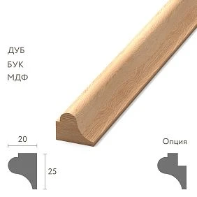
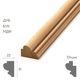
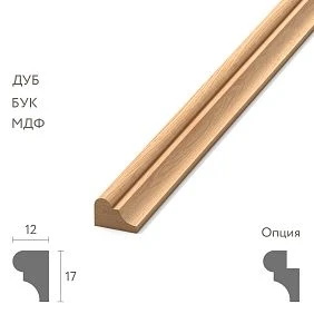
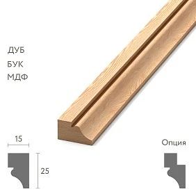
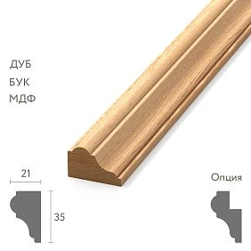
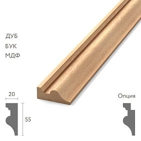
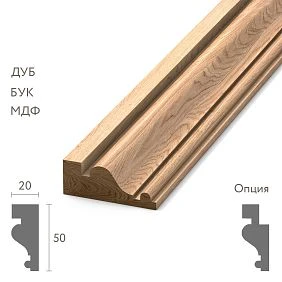
3. Choose the line pattern while keeping one profile
First compare several schemes with the same molding. This makes it clear what the composition itself changes and what is related to the new section. Changing the profile at the same time as changing the layout makes the choice more difficult.
| Technique | What it highlights | What to Check |
|---|---|---|
| One large frame | A unified wall field or panel | Relationship with furniture and free edges |
| Several vertical frames | Repeating rhythm | Width of the wall sections and intervals |
| Nested contours | Depth of the frame | Size of the central field |
| Horizontal belt | Overall level of several sections | Doors, furniture, and line endings |
| Asymmetric grid | Offset compositional center | The reason for each step change |
Many small frames create more turns and repeats. One large frame leaves more continuous surface. Neither option is automatically better: several frames can support a row of doors, while a large field can unify the wall behind a sofa.
Change one parameter at a time: the number of fields, their proportions, or the intervals. If the result improved only after changing all the decor at once, it is difficult to understand which decision should be kept in the project.
Get Consultation
4. Nested frames: count the space between the edges
A nested frame consists of an outer contour, a free band, and an inner contour. It can be made with one profile twice or with two different ones. In both cases, the outer dimensions, the width of each item, and the distance between the nearest edges are specified.
Let us consider a conventional composition 1200 mm wide and 2000 mm high along the outer edge. The outer molding takes up 35 mm, the free band between the contours is 40 mm, and the inner molding is 20 mm. All elements are in the same wall plane.
The outer width of the inner frame will be 1200 − 2 × (35 + 40) = 1050 mm. Its outer height is 1850 mm. After subtracting the two inner profiles, the central free field will be 1010 × 1810 mm.
The 40 mm band here is a condition of the example, not a recommended minimum. It is selected based on the scale of the wall and the feasibility of the finishing. A gap that is too tight may be hard to read or inconvenient to paint.
If an image of a given size needs to be placed inside, the calculation starts from this image and the required margins around it. Then the inner profile, the gap, and the outer framing are added. The direction of the calculation depends on which dimension cannot be changed.
5. Two moldings next to each other can form a complex contour
Paired lines differ from widely spaced nested frames: they are perceived as a single framing with several relief transitions. At the same time, physically they remain two separate items, each with its own base and installation method.
For example, two profiles 35 and 20 mm wide with a conventional gap of 8 mm will occupy a total band of 63 mm. If both are 12 mm thick and are mounted on the same installation plane, their thicknesses do not add up to 24 mm. The maximum protrusion is determined by the installed sections and the layers of the base.
Check the cross-section of such a pair. A narrow dark stripe may appear between the profiles; closely spaced beads can merge into a single relief, while identical protrusions can create a pronounced double rhythm. The result depends on the light and viewing distance.
Pay special attention to the corners. When parallel contours are spaced apart, their lengths differ, so you cannot cut identical sets for both lines. First build each contour in full, and only then compile the list of segments.
Do not use a narrow gap as a way to hide an unverified junction. You need to understand how to prepare, paint, and maintain the visible strip of wall between the products.
6. Select real widths and relief for the chosen scheme
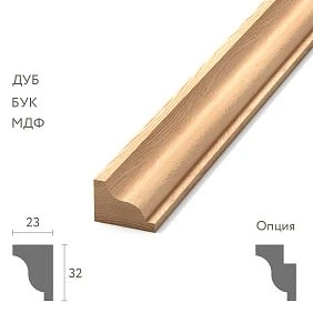
In a conventional double frame, you can consider molding MLDPU-003 measuring 35 × 12 × 2600 mm for the outer contour and MLDPU-027 in the 20 × 12 × 2600 mm version for the inner one. This is an example for verification, not a universal ready-made composition.
The first profile has a multi-level section, the second is semicircular. With the same thickness of 12 mm, they produce different relief lines. MLDPU-027 also has a 14 × 9 × 2600 mm variant: it cannot be substituted into the calculation in place of the 20 mm one without changing the field dimensions.
A wide molding is conveniently regarded as the main contour, and a narrow one as subordinate. But two profiles of equal width can also be appropriate if a uniform double rhythm is needed. The hierarchy is determined not only by width but also by placement, color, and the character of the section.
When the layout itself is complex, one item often helps preserve its legibility. A second one is introduced for a clear function: inner framing, a different scale, or a special area.
7. Justify the symmetry or offset of the composition
Symmetry is convenient to build relative to a panel, a bed, or a central door portal. But the center of the furniture and the center of the wall do not have to coincide. With a fixed asymmetrical arrangement, the frames can support the furniture group specifically.
For example, if there is a built-in wardrobe on the left, a large frame behind the sofa can occupy the remaining field, while a small side contour completes it near the door. The difference in sizes becomes a consequence of the room's layout rather than an accidental violation of the grid.
Check the empty gaps as carefully as the frames themselves. A narrow residual strip near the door casing often reveals an unprepared layout. It is better to eliminate it by revising the entire adjacent field than to add another short molding.
The same profile can be used in the living room with large frames, in the hallway with vertical fields, and in the bedroom as a headboard surround. The connection between the rooms will be preserved by the cross-section and coordinated finishing techniques. Full copying of the layout is not required for this.
Asymmetry must be defined by dimensions. The instruction "shift slightly to the right" leaves the compositional decision to the executor, which should be made by the project author.
8. Around the door, design both the lines and the endings
The door portal already contains its own verticals, horizontals, and projections. Wall moldings can continue this structure or form an independent field next to it. First, choose one of these options.
If the top of the frames is tied to the top of the door casing, determine the exact line: the top edge, the profile axis, or the inner edge of the field. The same mark without such clarification can lead to a small but noticeable discrepancy.
When directly adjoining, compare the projections of the parts. A molding that is thicker than the adjacent door casing can leave a visible end face. The ending must be shown in advance: a gap, a profile return, an intermediate element, or another agreed solution.
For the door leaf, additionally check the opening and the gaps along its edges. The decorative line must not connect the fixed wall and the moving part. Continuing the pattern across the door requires a separate diagram for each surface.
Polyurethane moldings and cornices are also compared on a common unfolded view. The upper band of the frames must not accidentally end up behind the cornice or form a tight strip next to it that was not present in the original sketch.
9. Add the ornament to an already defined field
The frame defines the boundaries and scale, while the overlay occupies a specific place within this structure. For a new composition, it is convenient to first define the inner field, then choose a central or corner accent. If the project already has a valuable historical detail, the sequence may be reversed: its actual dimensions become the initial constraint.
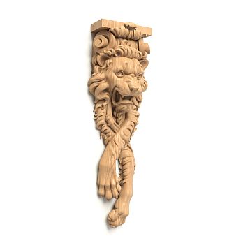
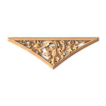
Choosing decorative polyurethane elements, show the full overall dimensions of the detail on the unfolded view. In a floral ornament, the outer leaves may extend far beyond the central part. Evaluating it only by its visual center is not enough.
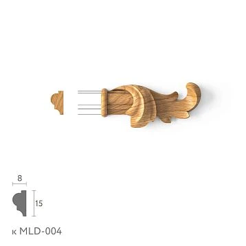
To include a detail directly in the frame line, select a compatible Decor for Molding. A separate overlay within the field and a corner element connecting the profiles require different checks.
Another technique is one band made of ornamental trim against a background of smooth lines. There is no universal ratio of smooth to ornamental decor. Check the repetition of the motif, its start at the edge, and its behavior at the corners: an accidentally cropped expressive element can change the impression of the entire wall.
10. Color and light change the number of noticeable lines
Molding in the wall color is perceived primarily through form and light-and-shadow. This helps tie a complex layout to the surface, but does not make it invisible. Under side lighting, each projection continues to cast its own shadow.
Contrasting paint emphasizes contours even with slight relief. If the composition becomes too active, try reducing the number of lines before changing all the profiles. Sometimes a single contrasting frame solves the task for which a double border was considered in a monochrome version.
Also compare sheen. The same wall and molding color at different sheen levels can read as two different finishes. The sample must reproduce the intended result, including surface preparation.
For paired profiles, check daylight and the specified fixtures. With one light direction, the gap between them is clearly visible; with another, it may blend into shadow. Do not substitute this check with random dramatic lighting in the visualization.
If the wall already has expressive texture, first evaluate it together with a simple contour. Additional ornament or color is introduced after checking what role the base itself already plays.
11. Check the curved section before approving the design
An oval frame or rounded top requires an actual product capable of working in such geometry. Drawing an arc in the model is not enough. The permissible radius, bend direction, and installation method of the specific profile must be confirmed.
Flexible polyurethane molding should not be considered an automatic option for any article. The material and the availability of a special flexible version are different pieces of information. For the selected contour, both are verified, and then the transition to straight segments is checked.
For a pair of “straight section — arc,” the required section lines must match. A slight difference in the position of the bead or edge will be noticeable in continuous framing even after overall painting.
If the solution is not confirmed, you can change the radius, choose another profile for the entire contour, or separate the curved part with an independent termination. Making it from short straight segments is acceptable only as a deliberately designed broken pattern: such an assembly will not become a smooth arc.
12. Check four different views in the 3D model
The general view of the room shows how the frames relate to the furniture. The frontal view of the wall shows the intervals and proportions of the margins. The side-lit view shows the relief and shadows. The close-up fragment shows how two profiles, a corner or an overlay are joined.
For such a check, use 3D models and DWG STAVROS with article numbers corresponding to the selected products. If the file contains several versions, set exactly the size that was included in the calculation.
You cannot turn a 35 × 12 mm profile into a 55 × 8 mm one by changing the scale and keep the same article number. The new image no longer corresponds to the product. Either choose a different product or change the composition: the gap, the second contour, the frame size.
Compare options with the camera in the same position and with the same materials. Otherwise one profile may seem better only because of more favorable lighting.
After choosing, save the view in which all essential parts of the composition are legible. A strongly perspective image with the furniture hidden by a wall is convenient for a presentation, but insufficient for agreeing exact dimensions and quantities.
13. Convert the drawing into a development and detail nodes
On the working drawing, each line is assigned an article number, size, position and method of termination. For nested frames, the outer dimensions and the gap between the edges are specified separately. Centerline dimensions may be used, but they must be labeled specifically as centerline dimensions.
Show the mounting plane on the section. Two profiles of equal thickness on the wall and on an additional panel will have a different overall projection. In the model this difference is sometimes hidden by color, but on site it will show up at the junction.
At intersections, decide which line continues, which ends, and what the joint looks like. Simply overlapping two volumes in the program does not describe how the node is manufactured. You need actual connection surfaces, and if necessary, a separate insert.
Check door opening, access to switches, and the ability to remove equipment. These actions must remain feasible with the decor installed, not only on an empty elevation.
The elevation, nodes, and 3D model must represent a single version of the composition. If you changed the internal profile, update not only the label but also the remaining field, segments, and purchasing quantity.
14. Assemble a trial fragment with the finish
For a double frame, a fragment with both straight lines, the gap, and at least one corner is useful. For a composition with an overlay, add its actual connection or position within the frame. A short sample of a single molding does not show how the parts work together.
Section samples and catalogs helps choose a material for a preliminary introduction, but the composition of each set must be checked. Testing a specific node may require individual products or agreed-upon cut lengths.
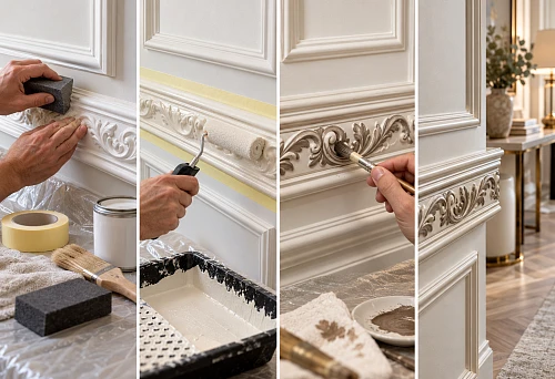
On the trial base, reproduce the wall color, the decor coating, and the selected interval. Look at the fragment from a working distance. Assess whether the contours are distinguishable, whether there is enough space for neat painting, and whether the joint becomes the main noticeable detail.
Record the approved dimensions, color, and gloss. If, after the trial, the gap was increased from 8 to 12 mm, this change must be carried over into the drawing and calculation, not left as a verbal decision by the installer.
A trial fragment is especially useful for closely spaced profiles: it checks both the appearance and the feasibility of finishing at real scale.
15. When a custom-designed profile is needed
Custom manufacturing of polyurethane moldings is considered when the catalog and permissible combinations of ready-made parts do not solve a specific limitation. This may be a precise historical profile, a custom ornament, a required joint, or a spatial shape for which there is no suitable standard product.
First, separate the mandatory parameter from the desired impression. If a wider decorative band is needed, it can sometimes be achieved with a pair of ready-made profiles. If an existing profile must be reproduced precisely in a continuous line, such a replacement may be unacceptable.
В STAVROS answers to questions about ordering it is stated that non-standard products made to custom designs are accepted for production subject to a minimum run. The possibility of a specific development, the volume, and the terms must be agreed upon; single-unit manufacturing cannot be promised automatically.
Custom-made stucco requires its own specification: profiles, dimensions, material, number of items, joining method, and a sample for approval. This work is justified when the difference is truly necessary for the project. The desire to make a wall individual does not in itself mean that a new profile needs to be developed.
16. Tie the composition to specific products
For the example considered, create a short table. Project codes denote the role in the composition, and SKUs denote the actual products.
| Code | Role | Item code and version | A, mm | C, mm | L, mm |
|---|---|---|---|---|---|
| M-01 | Outer frame | MLDPU-003, polyurethane | 35 | 12 | 2600 |
| M-02 | Inner frame | MLDPU-027, polyurethane, variant 20 × 12 mm | 20 | 12 | 2600 |
A link to the product, finish, room, and elevation number is added to the table. A separate row with full dimensions and quantity in pieces is provided for the overlay. Piece-by-piece decor cannot be included in the linear meters of linear profile.
Specify the surface condition at delivery and the final finish. The wording "white molding" does not explain whether it refers to the supplied product or to the agreed painted result.
A decision is considered defined when each contour corresponds to a specific execution. The entry "analog based on photo" leaves both the appearance and the dimensions open. Any replacement after approval requires checking the affected fields and joints.
17. Count both contours and cut each item separately
Let's return to the outer frame 1200 × 2000 mm and the inner one 1050 × 1850 mm. In the example, rectangular frames are assembled with mitered corners, and the segment dimensions are given along the long outer edges. All sides are made as single pieces.
| Contour | Ready-made segments | Total length | Strips 2600 mm up to reserve |
|---|---|---|---|
| Outer, M-01 | 2 × 2000 mm and 2 × 1200 mm | 6.4 m | 3 |
| Internal, M-02 | 2 at 1850 mm and 2 at 1050 mm | 5.8 m | 3 |
| The entire composition | 8 segments of two profiles | 12.2 m | 6 |
For the outer frame, the two long sides each take a separate strip. The two short sides are placed on the third: 2400 mm before allowance for processing. For the inner frame, the two 1850 mm sides also require separate blanks, while the two 1050 mm sides are placed on the third.
In the cutting map, the kerfs, end trimming and section direction are additionally checked. In this example, the proposed placement leaves room for processing, but the final sequence of cuts is set according to the actual product.
Using only one outer perimeter would give just 6.4 m instead of 12.2 m. And dividing the total linear meters by the retail length would give five strips after rounding instead of six. The reserve is added separately for each profile: leftovers of the outer molding do not replace the inner one.
18. How to take a custom layout through to ordering and installation
Before buy polyurethane moldings, match the order against the approved table and cutting map. Check the execution dimensions, material, retail length, number of strips and separately accounted decor. Availability and delivery terms are confirmed for the selected items.
If the composition includes Polyurethane trim with a pattern, attach its layout to the specification sheet. When transferring the project via the section for designers and architects highlight the questions about corners, radii and complex junctions. This is how a specific solution is discussed.
After receiving, distribute the products by project codes and keep a reserve. Before mass cutting, check the first frame on the finished wall: outer dimension, gap, position relative to the door and furniture. An error between the axis and the edge is detected here earlier than it will be repeated throughout the entire room.
Designer moldings deliver a signature result when the placement of each standard element is tied to the wall's purpose. A well-thought-out layout preserves this connection from the first lines of the sketch to the actual profiles, their finishing and installation.