Article Contents:
- Short answer: first choose the position of the profile, then make the cut
- What is confirmed for MLD-014 and why each parameter affects the result
- Main characteristics of MLD-014
- Which edge adjoins the surface
- Where the inner edge of the frame will be
- Where the convex part is directed
- What overhang remains above the facade
- Where will the main shadow fall
- Why the designations 'A', 'B', '1', and '2' often don't work
- Where to place the labels
- How to mark the inner edge
- How to work with oak
- How to mark multiple frames on one facade
- On a horizontal surface
- In a vertical position
- With side lighting
- Next to the handle and panel
- From a distance
- MLD-014 made of MDF
- MLD-014 made of beech
- MLD-014 made of oak
- What to choose under enamel
- When oak is appropriate
- For a cabinet facade
- For a dresser or nightstand
- For kitchen fronts
- For wall panels
- For a painted modern interior
- For classic furniture
- For DIY work
- For serial production
- Choosing only by photo
- Marking after cutting
- Checking only one corner
- Flipping at the miter saw
- Using leftover pieces without names
- Calculation based only on total linear meters
- Transferring calculation from one material to another
- Ignoring the handle
- Too little distance to the panel
- Finishing before test assembly
- Mixing parts after painting
- Verbal technical specification
- Expectation of full interchangeability of parts
- Can the correct side of MLD-014 be determined from a photo?
- Why did the corners align, but the frame looks crooked?
- How to understand which way to direct the convexity?
- Is it enough to assemble one test corner?
- Do I need to mark the parts if there is only one frame?
- Can I swap the top and bottom strips?
- Which material to choose for enamel?
- When should I choose oak MLD-014?
- What lengths is MLD-014 available in?
- How to Calculate the Amount of Molding?
- Can short offcuts be used?
- What should I do if one side looks different after painting?
- Do I need to account for the handle when calculating the frame?
- Can MLD-014 be mounted on a wall?
- How is MLD-014 different from a flat decorative strip?
- Can I order MLD-014 with a rabbet cut?
- What should I buy together with MLD-014?
- When is the best time to order samples?
- How should cut pieces be stored before installation?
- Where can I see the price for MLD-014?
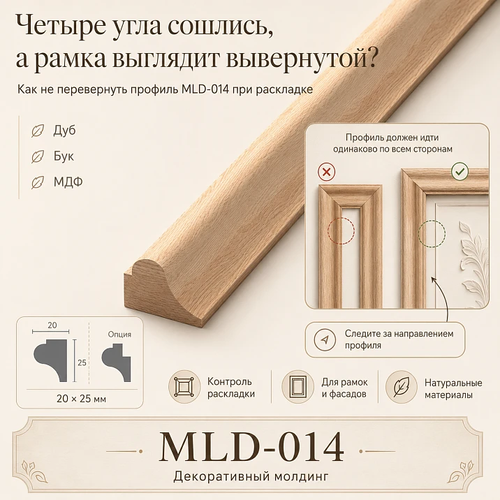
A frame can have precise dimensions, tight joints, and neat 45-degree miters—and still look wrong. The reason is found not in millimeters or tool quality. One of the strips is simply turned the other way. The convex line of the quarter-round profile went in the opposite direction, the shadow broke, and the assembled contour began to look like a composition of different parts.
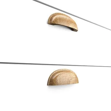
This error is especially noticeable when using the wooden molding MLD-014 with its expressive quarter-round cross-section of 25 × 20 mm. This profile cannot be perceived as a flat decorative rail, where it is enough to distinguish the front and back surfaces. It has a directional shape: one edge sits against the base, the arc forms the relief, and the transition between the high and low parts creates a shadow. Flip the strip—and the visual logic of the frame changes, even if the geometry of the joints remains flawless.
Therefore, working with MLD-014 does not start at the miter saw. First, the profile is applied to the facade or panel, the inner and outer contours are determined, the position of the convex part is checked, markings are made on the back side, and a test composition is assembled. Only after this can you calculate the length of the pieces, create a cutting plan, and place an order.
A buyer who plans buy wooden molding MLD-014, it is necessary to evaluate not only the material and length of the strip. No less significant are the cross-section drawing, the direction of the profile, the position of the frame relative to handles and the panel, future painting, the installation scheme, and the number of identical facades. This approach protects against an error that is hard to notice at the workbench but impossible to miss on finished furniture.
Short answer: first choose the position of the profile, then make the cut
A 45-degree cut is only responsible for joining two parts. It shows whether the ends can form a right angle without a noticeable gap. However, a precise cut says nothing about whether the strips themselves are oriented the same way.
To make the MLD-014 frame look solid, five checks must be performed before cutting:
-
Determine which face of the profile will be adjacent to the facade, wall panel, or other base.
-
Fix where the convex part should be directed.
-
Mark the inner edge of the frame on each strip.
-
Lay out the four sides into a full rectangle before cutting.
-
Assemble a test mock-up and look at it under side lighting.
The main rule can be stated strictly: the strip cannot be flipped after its position is approved. The workpiece may be moved, carried to the saw, placed on the work surface, but its orientation relative to the inner contour of the frame must remain unchanged.
In the workshop, they often reason differently: first we cut the parts, then we figure out which side to place them. For a flat strip, this approach sometimes passes without consequences. For a quarter-round profile, it is dangerous. After cutting, two outwardly similar parts may turn out to be non-interchangeable. One is intended for the left side, the other for the right, the top cannot always become the bottom, and the remainder of one strip cannot be transferred to another section of the frame without checking.
The correct sequence is the reverse:
drawing → fitting → orientation selection → marking → full layout → test angle → cutting → inspection → finishing → installation.
This chain seems longer than the usual approach, but it actually saves time. A few minutes on marking cost significantly less than repurchasing molding, redoing painted parts, or dismantling a frame from a finished facade.




What is confirmed for MLD-014 and why each parameter affects the result
MLD-014 is a quarter-round furniture molding. Its expressiveness is built not on complex carving, but on a clear three-dimensional form. The profile creates a smooth transition from the facade surface to the protruding frame line, so it can work both as a standalone framing and as part of a more complex composition.
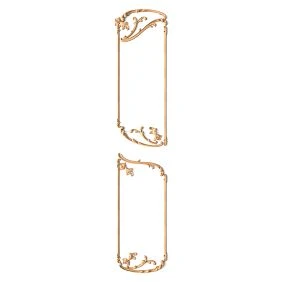
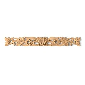
Our factory also produces:
Key characteristics of MLD-014
| Parameter | Confirmed value | What this means for the buyer |
|---|---|---|
| Article number | MLD-014 | Allows you to accurately order the same profile for a project or a repeat batch |
| Type | Quarter-round molding | The profile has a directional convexity, so it cannot be arbitrarily flipped |
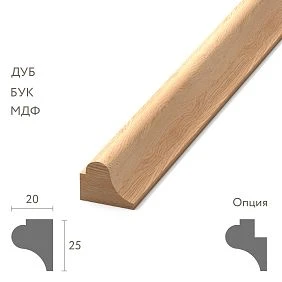
| Cross-section | 25 × 20 mm | You need to check both edges, the relief height, the overhang, and the shadow position |
| Length from MDF | 2600 мм | When calculating, the frame length, corner cuts, cutting map, and allowance are taken into account |
| Beech length | 2400 мм | The layout should be made separately, not using the calculation for MDF |
| Oak length | 2400 мм | It is necessary to take into account not only the cutting, but also the direction of the natural wood grain |
| Materials | MDF, beech, oak | The material is selected taking into account the future finishing and the overall character of the furniture |
| Sanding | «Prestige» | The surface is prepared for further finishing in accordance with the selected material |
| MDF | For enamel | Suitable for painted facades and smooth opaque coatings |
| Beech | For enamel | Allows the use of wooden profile in a painted furniture composition |
| Oak | For tinting | Preserves the visibility of the natural wood grain |
| Drawing | Published in the card | It determines the position of the faces, orientation, and actual profile geometry |
| Additional processing | Quarter cutout is possible per technical specification | For a serial project, the processing side must be fixed in advance |
| Condition for additional processing | From 30 items per card data | Before placing a batch order, the condition must be rechecked |
MLD-014 cannot be selected based only on a photo of the front side. The image shows the general nature of the product but does not answer key production questions: which face is 25 mm, which is 20 mm, where the line of maximum protrusion runs, how the profile fits against the plane, and where the shadow will fall with the chosen orientation.
Therefore, before ordering, you should and compare it with your own facade. Not mentally, but literally: draw a cross-section, mark the wall or facade plane, designate the inner side of the frame, and check how the arc will look in its actual position. The 25 × 20 mm section cannot be read as an abstract pair of numbers. These dimensions describe a shape that affects fit, visible width, shadow depth, distance to adjacent decor, and free space around the furniture handle. The molding may physically fit in the chosen area, but visually turn out to be too close to the panel or the edge of the facade. That is why the drawing must be considered together with the layout of the future frame.
Why four precise corners do not yet make a correct frame
Get Consultation
Let's imagine a typical situation. A craftsman set up a miter saw, checked the angle, made a few test cuts. Each pair of parts connects tightly. The diagonals of the finished rectangle match. From a technical standpoint, the frame is assembled correctly.
But after installation on the facade, it becomes noticeable that the left side looks wider than the right. The top rail catches light softly, while the bottom forms a heavy dark strip. In one corner, the arc continues the adjacent profile, in another it seems to break off.
The problem arose before the cut: the parts were lying in different positions.
A quarter-round profile has a visual direction. The convex part can be facing inward or outward of the frame. Both options are theoretically possible if the chosen position matches the project. The mistake lies not in the direction itself, but in its inconsistency. All four sides must follow one scheme.
A 45-degree miter cut controls:
the angle between parts;
-
the angle between parts;
-
joint density;
-
end alignment;
-
rectangle geometry;
-
absence of a large gap.
He does not control:
-
direction of the convex arc;
-
inner and outer sides of the profile;
-
continuity of light and shadow;
-
identical visual projection;
-
position of the molding relative to the panel;
-
orientation of the wood grain pattern;
-
correctness of the face side of each piece.
This is where the deceptive feeling arises: since the angle fits, it means everything is done correctly. In reality, the joint may be geometrically precise but compositionally wrong.
This problem often appears when transferring pieces to the saw. On the table, the frame was laid out correctly, but there was no marking. The craftsman picked up one blank, turned it for cutting convenience, placed it on the machine with a different face, and failed to restore the original orientation. After the first cut, the error became fixed in the piece.
Another common scenario involves offcuts. Long sides are made from full-length strips, while short sides are cut from suitable scraps. Externally, the scraps look identical, so they are taken without checking. One of them ends up rotated relative to the other frame parts.
A correct frame starts not with cutting precision, but with positional discipline. The tool can ensure a good angle, but only marking preserves the profile direction.
Section 25 × 20 mm: why it must be read together with the drawing
The phrase "molding 25 × 20 mm" seems specific enough. The buyer knows the width and height, can draw a rectangle on the facade, and check if the piece fits. But for a quarter-round profile, the nominal dimension does not equal its visual width.
The 25 × 20 mm rectangle only bounds the section. Inside it are the arc, transitions, and contact points. They determine which part of the profile will be lit, where a soft halftone will appear, and how deep the shadow boundary will be.
Before ordering and cutting, five questions must be answered.
Which edge is adjacent to the surface
One of the main edges must lie on the plane of the facade or panel. It cannot be chosen randomly just because it is more convenient to lay the profile on the table. The height of the protrusion and the direction of the arc depend on the position of the supporting edge.
Where will the inner edge of the frame be
The inner edge is considered to be the one facing the central field of the facade, panel, mirror, decorative insert, or free space inside the contour. It must be marked on each strip. The inscription "inside the frame" is more useful than the conventional designations "side A" and "side B", because it immediately connects the part with the future composition.
Which direction is the convex part facing
The arc can enhance the inner contour or create a more active outer transition. The choice depends on the task. In one project, the profile should gently guide the eye to the panel. In another, it should outline the outer perimeter and separate the frame from the plane of the facade. There is no universal position for all projects.
What overhang remains above the facade
The profile occupies not only area on the plane but also volume. It may end up too close to a protruding panel, handle, adjacent frame, cornice, or door edge. Checking only by width will not reveal a possible collision of parts.
Where will the main shadow pass
The shadow is not a random effect but part of the appearance of the quarter-round molding. Under side lighting, one side of the arc remains light, the other becomes darker. If the profile is rotated on one strip, the shadow line changes position and reveals the error faster than a ruler.
The drawing allows linking dimensions to the actual position. The buyer does not need to perform complex engineering calculations. It is enough to print or redraw the section, mark the base and inner contour, and then check whether this orientation matches the desired result.
Directional shadow: an invisible line that gathers the frame
Furniture molding is perceived not only by its contour. The eye reads the alternation of light, halftones, and shadows. It is they that show the depth of the profile and make a flat facade look more voluminous.
For a flat decorative batten, the shadow usually forms along the protruding edge. For the quarter-round MLD-014, light glides smoothly along the arc. The transition is soft but directional. If all sides of the frame are oriented the same way, this light-and-shadow effect continuously wraps around the rectangle.
When one batten is flipped over, several changes occur at once:
-
the light area shifts;
-
the deep shadow ends up on the other side;
-
the visible width of the profile seems different;
-
the corner is no longer perceived as a single rotation;
-
one side looks more massive than the adjacent one;
-
the frame loses its uniform rhythm.
On an untreated workpiece, the difference is sometimes hard to notice. Wood has its own grain, work lighting is diffused, and parts lie horizontally. After painting, the situation changes. Solid-color enamel emphasizes geometry, and the vertical position of the facade enhances shadows.
Therefore, MLD-014 should be checked not only from above while standing at the workbench. The test frame is lifted vertically and viewed from a normal distance: roughly how a cabinet, dresser, door panel, or wall composition will be perceived.
It is useful to direct light from the side. No special studio equipment is required. Natural light from a window or a portable source placed at an angle is sufficient. If the shadow runs continuously along the frame, the orientation is correct. If on one side it jumps to the other edge, the part is rotated.
Photography also helps. At close range, the craftsman focuses on joints and minor defects. A shot taken from several meters away shows the frame as a whole. A violation of direction often becomes obvious on the screen.
This check is especially useful in serial production. One approved sample can be photographed and used as a visual reference. Then the worker compares each new frame against it before gluing.
Where is the inner and where is the outer contour of the frame
The words "inward" and "outward" seem obvious while the craftsman has an assembled rectangle in front of him. Once the parts are spread across different work areas, spatial logic disappears. A separate strip no longer hints which side should face the center.
The inner contour faces the space that the frame encloses. This could be:
-
a furniture facade panel;
-
flat central field of the door;
-
decorative panel;
-
mirror or insert;
-
wall section;
-
free zone within the wall composition.
The outer contour is directed toward the edge of the facade or surrounding plane.
Before cutting, it is useful to draw the future rectangle on paper, a sheet of packaging cardboard, painter's tape, or directly on the protective film of the facade. Then four full-size strips are laid along the lines and the profile position is chosen.
After approval, an arrow is drawn on the back side of each blank pointing to the inner contour. The arrow should remain clear regardless of how the part lies on the table. The inscription "INSIDE THE FRAME →" almost eliminates ambiguity.
For the top and bottom parts, the labels "TOP" and "BOTTOM" can be added. For vertical ones — "LEFT" and "RIGHT". Such marking seems redundant only until the first mistake. In practice, it is especially useful when assembling several facades of different widths at the same time.
One cannot rely only on the direction of the cut. After processing the ends, the left and right parts do differ, but the mistake could already have been made. Marking should precede the cut, not explain the finished part retroactively.
The correct inner contour also helps calculate the frame size. If the inner dimensions are known, the position relative to the panel can be controlled. If the outer dimension is known, it is easier to maintain the offset from the edge of the facade. In both cases, one measurement system should be chosen in advance and not mixed in the cutting map.
How to apply MLD-014 to a facade before purchasing the main batch
Even an exact drawing does not replace a real fitting. On paper, the profile is evaluated separately, but on the facade it begins to interact with the handle, panel, edge, neighboring decor, color, and lighting.
For a single small product, a test piece is sufficient. For a furniture set, kitchen, built-in wardrobe, or a series of wall panels, it is more reasonable to use physical samples. They allow you to understand how the profile behaves specifically in your project.
The OMLD-005 set card presents 84 samples of moldings, cornices, and plinths made of MDF, beech, and oak. Such a set is useful not only for a designer. A furniture manufacturer can apply different profiles to the facade, compare their scale, and show the client not a picture, but a real volume.
When you need check the molding profile at full scale, the sample should be applied in several positions:
-
with the convexity toward the central panel;
-
with the convexity toward the outer edge;
-
next to the panel;
-
near the handle;
-
at the assumed distance from the edge;
-
with vertical and horizontal light direction.
Often one option looks convincing on a horizontal part, but too heavy on a vertical one. This does not mean the profile has a different shape. The light, viewing angle, and the molding's relation to the facade proportions change.
It is useful to also apply the sample to adjacent furniture elements. If the cabinet consists of several doors, the frames should create a unified arrangement rather than compete with each other. On a narrow door, MLD-014 may occupy a noticeable part of the field; on a wide one, it may look calmer.
Physical fitting also helps in choosing the material. MDF, beech, and oak are perceived differently before and after finishing. For a final decision, not only a piece of material is needed, but also an understanding of the future coating.
To understand in detail why to check the molding with a physical sample, it is useful before calculating the entire batch. One sample can prevent the purchase of a profile that fits the numbers but does not match the furniture's scale.
Marking strips: a simple system that saves expensive work
Reliable marking does not have to be complex. Its task is to preserve the meaning of each part from layout to installation. Any person picking up a strip should understand where its top, bottom, front side, and inner edge of the frame are.
Minimum set of markings:
-
the facade number;
-
frame name, if there are several;
-
part position;
-
direction of the inner contour;
-
top of the product;
-
front surface;
-
material or batch for serial work.
Example of an inscription on the back side:
FACADE 01 — FRAME A — LEFT — TOP ↑ — INSIDE FRAME → — FRONT
It is not necessary to use exactly this wording. It is important that the system is uniform for the entire workshop.
Why the designations “A”, “B”, “1” and “2” often do not work
Conventional letters are clear to the person marking at the time of work. After a day, the meaning may be forgotten. Another craftsman does not know at all what “A” means: the inner edge, the first facade, the front surface, or the type of cut.
The words "LEFT", "RIGHT", "INWARD", "TOP" are read without decoding. The more obvious the marking, the less the result depends on memory.
Where to place inscriptions
The main marking is applied to the back side or to an area that will not remain visible after installation. Deep scratches must not be made on the front surface. For temporary marking, a pencil, painter's tape, or removable labels are suitable.
If the profile is to be painted before installation, some markings may disappear. In this case, duplicate the information on the packaging, tag, or a separate parts map. After applying primer, the strips must not become an unnamed set.
How to mark the inner edge
The most reliable sign is a long arrow pointing inward of the frame. It is applied along the back side of the part. The arrow must be visible before and after cutting.
Short transverse marks on the ends can be added, but they do not replace the main arrow. After cutting, part of the end disappears, and with it the marking may also disappear.
How to work with oak
When using oak MLD-014, the direction of the natural grain is added to the technical marking. Two parts may be geometrically identical but noticeably differ in the character of the fibers.
In one frame, the grain should look meaningful. This does not necessarily mean absolute symmetry, which is unattainable for natural material. It is important to avoid randomness: for example, when three sides have a calm longitudinal grain, and the fourth stands out sharply.
Before cutting, it is useful to lay out the oak planks nearby, evaluate the face surfaces, and assign each workpiece a specific place.
How to mark several frames on one facade
If the composition consists of outer and inner contours, the designations "left" and "right" are not enough. You should add a number or name of the frame:
-
facade 03, outer frame, left;
-
facade 03, inner frame, left;
-
facade 03, outer frame, top;
-
facade 03, inner frame, top.
Without this, a short part of the inner contour may accidentally end up in the outer frame, and the craftsman will notice the error only during final assembly.
First a full rectangle, then a miter saw
The correct layout of MLD-014 is done at full size. You should not limit yourself to two planks forming one corner. Such a fragment shows the joint but does not reveal the overall orientation of the four sides.
Place on a workbench or other flat surface:
-
the left vertical part;
-
the right vertical part;
-
the top rail;
-
the bottom rail.
If full-size blanks do not fit, use short samples, but each must maintain the real profile position.
In the center of the layout, you can place a schematic image of the facade or a sheet with the inscription "INSIDE THE FRAME". This simple technique prevents forgetting which side the inner contour faces.
Then check:
-
Whether all convex parts are oriented according to the same logic.
-
Whether the position of the deep shadow matches.
-
Is the visible overhang the same.
-
Are the top and bottom parts not flipped.
-
Is there enough distance to the edge of the facade.
-
Does the frame not conflict with the handle.
-
Is the required gap to the panel maintained.
After approval, each strip is labeled. Only then are the parts moved to the miter saw.
It is better to move them one at a time, without disassembling the entire layout at once. The craftsman takes a specific strip, checks the label, makes the cut, and returns the part to its designated place. The next workpiece is processed after a repeated check.
With this order, the frame remains visible at all times. Errors do not accumulate unnoticed. If one strip is accidentally flipped near the saw, the discrepancy is detected when returning to the overall rectangle.
Why the part is flipped specifically near the saw
The miter saw dictates a convenient position for the workpiece. For a left cut, the craftsman lays the profile one way; for a right cut, he turns it. The problem begins when a turn in the plane is confused with a flip to the other face.
A rotation in the plane keeps the face side up. A flip changes the position of the profile relative to the base. Externally, these actions look similar: the workpiece was picked up and moved. But for a quarter-round molding, the consequences are different.
The risk increases when:
-
marks are applied only on the ends;
-
the back side is not labeled;
-
the work area is poorly lit;
-
several parts lie in a common stack;
-
the cutting is performed by a person who did not participate in the fitting;
-
the remnants are stored without marking;
-
left and right strips are cut mixed together;
-
the template exists only in the master's memory.
A simple rule helps: the "FACE" inscription must remain in a pre-set position during all cuts. If the technology requires laying the profile differently, the craftsman first checks the drawing and cutting map, rather than acting automatically.
For a series of identical frames, it is useful to prepare a physical reference of a short part. It is kept near the saw and compared with each new workpiece. This is faster than mentally reconstructing the cross-section position each time.
Remnants after cutting are also labeled. They indicate the material, length, profile orientation, and the original frame. This way, a short piece can be safely used later, rather than becoming a potential cause of an inverted side.
Test corner: what it shows and what it cannot show
The test corner is assembled from two short pieces of MLD-014. It is needed before cutting the main batch, especially if the craftsman is working with this profile for the first time or the project involves complex finishing.
Such a sample allows checking:
-
quality of the 45-degree cut;
-
joint density;
-
alignment of arcs;
-
appearance of the transition;
-
visibility of the joint line;
-
the profile's reaction to primer, enamel, or tinting;
-
a suitable method of fixation.
However, one corner does not answer whether the entire frame is assembled correctly. Two parts may be aligned with each other, but the overall outline may be rotated differently than intended. Moreover, a single corner does not show how the profile will behave after four consecutive turns.
The test piece should be applied to the actual facade. Only then does it become clear in which direction the convexity should be directed. On an empty workbench, both options may seem acceptable, but next to the panel, one of them immediately looks more convincing.
If the product is to be painted, it is useful to finish the test corner using the future technology. After applying a solid-color coating, small differences in shape become more noticeable. With oak, tinting, on the contrary, emphasizes the natural structure, so the joint of the grain should also be evaluated.
A test corner is not an unnecessary expense. It is a control piece on which decisions can be checked without the risk of ruining a full-size frame.
Why it is better to assemble a mock-up from four short segments
A full test rectangle reveals errors that are not visible on a single corner. It does not require long pieces. Four short segments, cut and oriented in the same way as the future frame, are sufficient.
The mock-up is checked in several stages.
On a horizontal surface
First, the density of joints and continuity of shape are assessed. The inner contour is marked with a sheet of paper or a line. All arrows on the back side should be directed toward the center.
In a vertical position
The frame is lifted and placed at approximately the height of the future installation. Horizontal layout and vertical facade are perceived differently. In the working position, real light and shadow are revealed.
With side lighting
The light source is placed on the right, then on the left. A continuous shadow should wrap around the entire rectangle according to one logic. If it jumps on one side, the profile is flipped.
Near the handle and panel
The mockup is applied to the area where the frame will be located. Not only dimensions are checked, but also visual distance. The molding should not accidentally press the handle to the edge or create too tight a gap near the panel.
From a distance
Up close, the craftsman looks at the joints. The buyer perceives the furniture as a whole. Therefore, the mockup is photographed or evaluated from several meters away. It is there that the overall scale becomes apparent.
For a serial order, the approved layout becomes the reference standard. It can be stored together with the drawing, finishing sample, and cutting map.
Layout around a furniture handle: when millimeters exist, but there is no free space
The frame and handle are on the same plane, so they must be considered together. The error appears when the decorative contour is calculated first, and space for hardware is left on a "residual principle."
On the drawing, the handle may not intersect the molding, but that is not enough. You need to check:
-
whether fingers fit freely under the handle;
-
whether the handle base hits the profile protrusion;
-
whether the hardware looks squeezed between the frame and the edge;
-
whether the handle center aligns with the visual axis;
-
whether there is enough space for holes and fasteners;
-
whether the handle can be removed after molding installation.
The direction of the convex part also changes the perception of distance. When the high side of the profile faces the handle, the gap visually narrows. If the arc goes in the opposite direction, the space seems freer.
Therefore, fitting is done with a real handle or its exact template. The outline on paper does not show the protrusion and space for the hand.
On kitchen fronts, repeatability is especially important. Frames and handles must occupy the same position on all doors. If one MLD-014 strip is flipped, the shadow disruption will be noticeable not by itself, but in comparison with neighboring fronts.
Frame front and panel: how not to turn two reliefs into a narrow corridor
MLD-014 is often considered for decorating a flat field, but it can also be used next to a frame structure or panel. Special caution is required here: two volumetric transitions meet in a small area.
There must be a meaningful gap between the molding and the panel. Too small a distance creates a hard-to-finish gap and visually compresses the composition. Too large turns the profile into a random line unrelated to the central field.
The direction of the arc helps control the transition. A convexity facing the panel more actively connects the molding with the inner part of the front. The opposite position emphasizes the outer contour more strongly.
The choice should be made on a real sample. There is no universal norm in millimeters, because the result depends on the door size, panel depth, color, handle, and the total amount of decor.
Before ordering, check:
-
outer frame size;
-
inner size;
-
distance to the panel;
-
distance to the edge;
-
profile height above the plane;
-
possibility of even painting;
-
access to corners;
-
free movement of adjacent doors and drawers.
For a general understanding of the choice, you can study rules for selecting furniture molding, and then return to the specific task of MLD-014: maintaining one orientation on all four sides.
MLD-014 on a wall panel: the error becomes more noticeable with distance
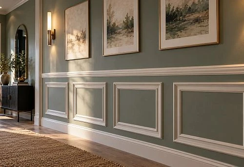
On the wall, the profile is perceived differently than on a small furniture facade. The frame is larger, the light source is usually above or to the side, and the viewer sees the composition from several meters away.
The inverted bar on the wall panel may not be noticeable during installation. The craftsman stands close and controls the joint. After finishing the work, one side starts to look heavier. In the evening, artificial light intensifies the difference.
Before cutting the wall frame, it is useful to make markings with painter's tape. It shows the overall size, indents from the floor, ceiling, doorways, and adjacent elements.
Then a short sample MLD-014 is applied to each side of the marking. This walk-around helps to see how light changes on vertical and horizontal sections. After choosing the position, the inner contour is marked on the diagram and transferred to each bar.
For a large frame, it is especially dangerous to confuse the direction when cutting long pieces. The top and bottom bars may be similar in length, so they are marked immediately after measuring.
If there will be several identical frames on the wall, one of them should become the control. The others are compared with it before gluing.
Several identical facades: why the first frame should become the standard
Serial work does not tolerate uncertainty. A mistake made on one facade can repeat on ten, twenty, or fifty products. Therefore, before batch cutting, not only the dimensions but also the orientation of the profile must be approved.
First, one control frame is assembled. It must go through the full cycle:
-
fitting;
-
marking;
-
cutting;
-
dry assembly;
-
checking diagonals;
-
shadow evaluation;
-
trial finishing;
-
fitting to the handle;
-
approval of the appearance.
After approval, a parts map is created.
| Part code | Facade | Position | Inner contour | Material | Workpiece length | Note |
|---|---|---|---|---|---|---|
| F01-L | 01 | Left | Right arrow | As per project | By calculation | Do not flip |
| F01-R | 01 | Right | Left arrow | As per project | By calculation | Check against reference |
| F01-T | 01 | Top | Down arrow | As per project | By calculation | Arc direction control |
| F01-B | 01 | Bottom | Up arrow | As per project | By calculation | Check handle position |
For identical facades, repeating dimensions can be used, but each part still receives a code. This simplifies control after painting, when geometrically similar strips are easy to confuse.
Batch cutting is performed by groups:
-
All left vertical parts.
-
All right vertical parts.
-
All top ones.
-
All bottom ones.
This order reduces the number of readjustments and helps maintain the profile position. However, it only works if there is a reference and clear marking.
Do not stack finished parts in a common pile. For each facade, prepare
For a complex series, first make a cutting diagram on paper or in a table. On each full-size strip, place future parts and label their codes. Only after that is the final quantity determined.
Before ordering, you should check current lengths of MLD-014, because the calculation for MDF cannot be automatically transferred to beech or oak.
MDF, beech, or oak: the material is chosen together with the finish.
MLD-014 is available in three materials. They cannot be considered identical blanks differing only in price. Each option defines its own finishing route and affects the perception of the frame.
| Material | Confirmed length | Preparation | For which tasks is it suitable | What to Check |
|---|---|---|---|---|
| MDF | 2600 мм | Prestige sanding, for enamel | Solid colored painted facades, panels, and frames | Compatibility of primer and enamel, cutting map for length 2600 mm |
| Beech | 2400 мм | Prestige sanding, for enamel | Painted furniture with wooden profile | Layout for length 2400 mm, test coating, shade stability |
| Oak | 2400 мм | Prestige sanding, for tinting | Projects where the natural wood grain needs to be preserved | Fiber direction, combination of parts, test tinting |
MLD-014 from MDF
MDF is convenient for a painted frame, where the main focus should remain on the geometry of the profile. A solid-color enamel unifies the molding with the facade and emphasizes the smooth quarter-round shape.
It is precisely after painting that an orientation error can become more noticeable. The material pattern no longer distracts the eye, and the chiaroscuro reads especially clearly. Therefore, before finishing, you need to make sure that all sides are laid out identically.
A length of 2600 mm may prove advantageous for certain cutting layouts, but the decision is made based on the specific frame dimensions. You cannot rely only on the total number of linear meters.
MLD-014 from beech
Beech is also prepared for enamel. This option is chosen when the project calls for a wooden profile, but the final surface must be painted.
Before serial work, it is useful to make a test paint-out. It shows how evenly the coating follows the relief, whether excessive runs form in the inner corners, and how the depth of shadow changes.
The strips have a length of 2400 mm, so the cutting layout is prepared separately. If the project was previously calculated for MDF, simply replacing the material without recalculating may lead to a shortage of items.
MLD-014 from oak
Oak is prepared for tinting. Here, the composition is created by two directions at once: the geometry of the quarter-round profile and the natural grain of the wood.
When laying out, it is not enough to mark only the inner side. The face surface of each strip, the nature of the fibers, and the transition between parts at the corners should be assessed.
Tinting can enhance differences. Therefore, a control sample is finished with the same composition and according to the same scheme planned for the entire furniture.
What to choose for enamel
If the frame must fully match the color of the facade, MDF or beech, confirmed as options for enamel, are considered. The choice between them depends on the project design, material requirements, and cutting plan.
When oak is appropriate
Oak is chosen not to imitate a solid-color surface, but when the wood grain must remain visible after tinting. In such a project, each strip requires individual layout.
If MLD-014 is not suitable in scale or cross-section character, you can open catalog of furniture moldings and compare other profiles from MDF, beech, and oak.
Test coating: why color changes the perception of the profile
An untreated molding and a finished painted frame can look different. The coating does not change the profile dimensions, but it changes the distribution of attention.
On light solid enamel, the arch is perceived as softer, and the shadow is cleaner. On dark coating, contrast may increase. A glossy surface reflects the light source more actively, while a matte surface shows volume more calmly. The specific result depends on the chosen finishing system, so it cannot be reliably predicted from the color description alone.
A test application is done on a short fragment or a control corner. It is advisable to use the same material, primer, and topcoat as in the main project.
After drying, the sample is evaluated:
-
in daylight;
-
under evening artificial lighting;
-
vertically;
-
near the facade;
-
with the selected handle;
-
from a distance.
Not only the shade is checked. It is necessary to see whether the frame has become too massive, how readable the quarter-round shape is, and whether the orientation error has increased.
Painting individual slats before a trial assembly is risky. After finishing, markings may disappear, and fitting joints becomes more difficult. The sequence of work is chosen according to the project's technology, but dry assembly and position control should precede final installation.
When quarter cutting is needed
In the MLD-014 card, the possibility of additional processing—quarter cutting per technical specification—is indicated. An order condition of 30 items is also specified. Since production conditions may change, they should be re-checked before placing an order for a batch.
Quarter sampling turns an ordinary profile into a part with a more strictly specified fit. After processing, it is no longer enough to write "make a groove at the back." In the technical specification, you need to show:
-
the side of the sampling;
-
its position relative to the front surface;
-
the inner and outer contour;
-
sizes;
-
the direction of the profile;
-
the place where the insert or adjacent part adjoins.
An error in orientation during additional processing costs more than flipping a standard blank on a workbench. The batch may be manufactured mirrored relative to the project.
To prepare documentation, it is useful to study how to fix the front orientation of the molding on the drawing. The main plot of that material is related to a different model, but the principle of an unambiguous technical specification also applies to the serial order MLD-014.
Before producing the batch, it is reasonable to approve a reference part. A verbal description does not replace a physical sample on which the face, inner edge, and processing side are marked.
How not to confuse MLD-014 with similar moldings
Quarter-round profiles may look similar in photos. The buyer sees a smooth arc and concludes that the models differ only in size. In reality, changing the cross-section affects the scale, shadow depth, fit, and the allowable distance to adjacent decor.
MLD-014 has a confirmed cross-section of 25 × 20 mm. Before replacing it with another model, you need to compare not just one width, but the full drawing.
Check:
-
both sides of the overall rectangle;
-
the shape of the arc;
-
protrusion height;
-
the width of the adjoining face;
-
the direction of the main shadow;
-
material;
-
the length of the strip;
-
preparation for finishing.
You cannot replace a profile just because a similar option is available in the workshop. Another model may have a different visual connection at the corner. The frame will change the scale, and the cutting calculation will lose accuracy.
When it is necessary to understand, how a quarter-round wooden profile is constructed, it is useful to compare MLD-005 and MLD-010. However, for the current project, the final decision is made based on the MLD-014 drawing and a real fitting.
MLD-014 should also not be confused with a flat decorative strip. A flat element can be almost symmetrical and less sensitive to flipping. The quarter-round profile creates directional light and shadow, so it requires strict orientation.
It also differs from a specially processed profile with a rabbet. The standard MLD-014 and a part made according to the technical specification may have different fits. The presence of additional processing is always checked in the order.
What to buy together with MLD-014
Molding rarely exists in a project on its own. For a confident result, physical samples, installation materials, finishing compounds, and other profiles for comparison may be needed.
| What to add to the purchase | Why this is needed | Which scenario it suits | What to pay attention to |
|---|---|---|---|
| Sample set OMLD-005 | Helps to check the cross-section and scale in full size | Kitchen, facade series, wall panels, project with client approval | Attach the sample in its actual position and under working lighting |
| Mounting materials | Needed for fixing the molding on a prepared base | Furniture facade, wall panel, decorative frame | The composition is selected according to the molding material, base, and future finish |
| Materials for painting | Allow making a test coat and finishing the frame | MLD-014 made of MDF or beech for enamel | Check compatibility of all finish layers |
| Tinting compositions | Emphasize the grain of the oak profile | MLD-014 made of oak | Run a test on a separate segment |
| Another profile for comparison | Helps choose the appropriate scale | When MLD-014 seems too noticeable or too subtle | Compare the full cross-section, not just the width |
| Control frame sample | Preserves the approved orientation | Serial production | Mark the face, top, and inner contour |
Before installation, you should choose glue for furniture decor taking into account the base and the selected material. No adhesive composition can be considered universal for MDF, beech, oak, painted surfaces, and wall panels.
For a complex order, a set of samples is especially useful. It allows you to compare several profiles without purchasing a full-size batch, coordinate the shape with a designer or client, and see in advance where the convex part should be directed.
Practical selection of MLD-014 for different tasks
The same profile can be used in different projects, but its layout scheme changes. The buyer needs to know not only the product, but also their own situation.
For a cabinet facade
On tall doors, the frame must maintain a single direction from top to bottom. Special attention is paid to long vertical strips. Even a slight difference in shadow becomes noticeable across the entire height.
Before ordering, check:
-
outer frame size;
-
indent from the edge;
-
hinge position;
-
distance to the handle;
-
alignment of frames on adjacent doors;
-
possibility of solid cutting of long sides.
For a dresser or nightstand
On low facades, MLD-014 occupies a large portion of the surface. A scale or orientation error becomes especially noticeable.
The frame is evaluated together with the handle and adjacent drawers. If several facades are positioned one above another, the profile direction must be repeated on each.
For kitchen facades
A kitchen consists of many doors and drawers. Here, consistency, uniform gaps, and checking all frames against a single standard are important.
The cutting plan is prepared before ordering. Parts are grouped by facade, and after finishing they are not mixed.
For a wall panel
On the wall, not only the frame is checked, but also the architectural surroundings: baseboards, cornices, door trims, outlets, and furniture. The full outline is first marked with painter's tape.
For a painted modern interior
A quarter-round molding does not have to be used only in a rich classical composition. With a calm layout and solid-color enamel, it can create a clean, three-dimensional outline without an abundance of ornament.
Here, precision of distances and quality of light and shadow are especially important. The decor should look like part of the facade's architecture, not like a randomly added strip.
For classic furniture
MLD-014 can be combined with panels and other decor, but the number of relief elements must be controlled. The frame should tie the composition together, not overload it.
Before purchasing, it is useful match the scale of the frame to the furniture, and then check the specific position of MLD-014 on the sample.
For independent work
A person without much experience should not try to determine the orientation after cutting. It is much safer to make a template, label each part, and first assemble a short mock-up.
The ready-made profile eliminates the need to independently manufacture a complex quarter-round cross-section. The work focuses on designing the frame, careful mitering, finishing, and installation.
For serial production
Required:
-
approved sample;
-
a drawing;
-
cutting map;
-
marking system;
-
separate kits for facades;
-
control after finishing;
-
fixing the direction of the oak grain;
-
clear technical specification for additional processing.
Mistakes that require redoing the frame
Choosing only by photo
The photo shows the general view but does not reveal the exact cross-section geometry. The buyer does not understand which edge will adjoin the facade and where the main shadow will be.
Solution: study the drawing and attach a physical sample.
Marking after cutting
When the inner edge is marked on already cut parts, the error may have been fixed by the cut. Some strips become mirrored relative to the project.
Solution: mark full-size blanks before the first cut.
Checking only one corner
Two parts may join correctly, but the full contour may not. A single corner does not show four consecutive profile rotations.
Solution: assemble a mock-up from four short segments.
Flip at the miter saw
The master changes the position of the workpiece for a convenient cut and loses the approved orientation.
Solution: use the labels "FACE" and "INSIDE THE FRAME", and return the part to the layout after each cut.
Using unnamed offcuts
A short piece fits in length, but its direction is unknown. To save material, it is installed in the frame, after which one side looks different.
Solution: label offcuts immediately after cutting.
Calculation based only on the total linear meters
The total length is sufficient, but individual sides do not fit into full-size planks. This leads to a shortage or an attempt to assemble the visible side from parts.
Solution: create a cutting map taking into account a length of 2600 mm for MDF and 2400 mm for beech and oak.
Transferring the calculation from one material to another
The project is calculated for MDF with a length of 2600 mm, and then the material is changed to beech or oak with a length of 2400 mm without a new scheme.
Solution: recalculate each strip and the number of items.
Ignoring the handle
The frame fits geometrically, but interferes with comfortable grip or visually pinches the hardware.
Solution: try the molding together with the actual handle.
Too little distance to the panel
A narrow, hard-to-reach gap forms between the two reliefs. It looks random and complicates finishing.
Solution: evaluate the distance on a full-size mockup.
Finishing before control assembly
The strips are painted, the markings have disappeared, and the joints and orientation have not been checked. Correction becomes more difficult.
Solution: perform a dry assembly and approve the position before final finishing.
Mixing parts after painting
Identical strips from different facades are stacked together. During installation, they are rearranged, disrupting the wood grain pattern or orientation.
Solution: store parts in sets and duplicate codes on tags.
Verbal technical specification
The phrase "make a cutout on the inner side" can be understood differently if the inner contour is not shown graphically.
Solution: attach a drawing, arrows, and a reference sample.
Expectation of full interchangeability of parts
The craftsman believes that the top strip can be turned into the bottom one, and the left one into the right one. After cutting and marking, this is not always possible.
Solution: assign each part a specific place before cutting.
Who is MLD-014 suitable for, and when is it better to choose a different profile
MLD-014 is worth considering if you need:
-
to assemble a voluminous furniture frame;
-
to emphasize the facade without complex carving;
-
to achieve a smooth quarter-round transition;
-
to design a wardrobe, dresser, nightstand, or kitchen door;
-
to create a wall frame;
-
to use MDF or beech under enamel;
-
to preserve the oak grain under tinting;
-
to repeat one profile across a series of facades;
-
to order additional processing for a large batch.
Another option may be more appropriate if:
-
the available area is already 25 × 20 mm;
-
there is not enough free space near the handle;
-
a nearly flat decorative line is required;
-
a larger architectural profile is needed;
-
the existing molding must be replaced without changing the old footprint;
-
the project requires a different cross-section or a different fit;
-
the profile must perform a structural function for which MLD-014 is not intended.
In such cases, it is better not to try to adapt MLD-014 at any cost, but to choose a different profile for the frameThe comparison should be made based on drawings, materials, lengths, and actual samples.
How to order MLD-014 on the STAVROS website
The purchase starts not with quantity, but with checking the project.
First, open the MLD-014 card and study:
-
cross-section drawing;
-
available materials;
-
length of the selected version;
-
preparation for finishing;
-
current price;
-
ordering conditions;
-
possibility of additional processing;
-
current requirements for the minimum batch for quarter sampling.
Then determine the position of the profile on the facade. Mark the inner contour, apply the sample near the handle and panel, check the shadow under side lighting.
After that, compile a list of parts and a cutting map. For each side, specify the length, position, and direction. For a serial project, add facade numbers.
If the shape is not yet approved, you can Buy OMLD-005 molding sample set and compare several profiles in real scale.
For the main batch, it is important to choose one material:
-
MDF 2600 mm long under enamel;
-
beech 2400 mm long under enamel;
-
oak 2400 mm long under tinting.
These options cannot be combined in one calculation. Each material requires its own cutting map.
For non-standard processing, prepare a technical specification. On the drawing, show the front surface, inner edge, sampling side, and required dimensions. The conditions of such processing should be confirmed with a manager before placing the order.
Ordering via STAVROS is convenient because the main profile, samples, and related materials can be selected as a single system, rather than assembling a project from random parts with unknown cross-sections.
Final checklist before purchase and cutting
Before placing an order, check:
-
MLD-014 is specifically selected.
-
Cross-section 25 × 20 mm verified against the drawing.
-
Material determined: MDF, beech, or oak.
-
Length of the selected version is taken into account.
-
Position of the convex part is approved.
-
Inner contour of the frame is marked.
-
Profile is applied to the actual facade or panel.
-
Distance to the handle is checked.
-
Distance to the panel and edge checked.
-
Test corner assembled.
-
Mockup of four sides assembled.
-
Test paint or tint applied.
-
Cutting map has been created.
-
Technological allowance added.
-
All slats marked.
-
Remnants will not be used without checking orientation.
-
Control sample made for the series.
-
Additional processing described on the drawing.
-
Current order conditions checked in the card.
FAQ: answers to common questions about MLD-014
Can the correct side of MLD-014 be determined from a photo?
A photo helps assess the overall profile character but does not replace a drawing and physical fitting. MLD-014 has no single universal side that must be internal in all projects. The position depends on the facade, panel, handle, and desired shadow direction.
First, study the 25 × 20 mm cross-section, then apply the profile to the base and fix the chosen orientation.
Why did the corners meet, but the frame looks crooked?
Precise cutting controls the joint geometry but not the position of the convex part. One or more strips could have been flipped. As a result, the shadow and visible profile width change, although the rectangle remains geometrically correct.
How to understand where to direct the convexity?
Apply the sample in two positions. Evaluate the transition to the central field, distance to the handle, connection with the panel, and the outer edge of the facade.
The chosen direction must be repeated on all four sides. After approval, mark the inner contour with an arrow.
Is it enough to assemble one test corner?
One corner shows the quality of the cut and the joint of two parts, but does not control the entire rectangle. It is more reliable to assemble a mock-up from four short segments and see how the shadow passes through all the turns.
Do parts need to be marked if there is only one frame?
Yes. The error often appears not because of the number of frames, but during transfer to the saw. Even four parts can be mixed up.
Minimal marking: top, position, face, and direction of the inner contour.
Can the top and bottom rails be swapped?
Before cutting and assigning parts, this is sometimes possible. After marking, end processing, and matching the wood grain, interchangeability may disappear.
It is better to assign each blank a specific place right away.
What material to choose for enamel?
In approved MLD-014 executions under enamel, MDF and beech are prepared. The decision depends on material requirements, rail length, cutting plan, and furniture construction.
Before the main finishing, do a test coat.
When to choose oak MLD-014?
Oak is suitable for a project under tinting where the visible wood grain must be preserved. When laying out, the direction of the fibers and the combination of face surfaces of adjacent slats must be taken into account.
What length is MLD-014 produced in?
The confirmed length of the MDF variant is 2600 mm. Beech and oak slats have a length of 2400 mm.
Before placing an order, the parameters should be re-checked in the product card.
How to calculate the amount of molding?
First, calculate the dimensions of the four sides of each frame. Then place the parts on full-size slats, taking into account the material, miter cuts, test cuts, and allowance.
Simply dividing the total perimeter by the length of one slat is not enough. A cutting map is needed.
Can short remnants be used?
Yes, if the remainder has sufficient length, a suitable face surface, and preserved marking. You cannot flip a segment just to make it fit into a free space on the cutting map.
What to do if one side looks different after painting?
First, check the direction of the profile. If the slat is flipped, the difference is not related to color, but to the changed light and shadow.
Before gluing, the part can be replaced or reoriented if the cuts allow. After installation, correction usually requires dismantling.
Should the handle be taken into account when calculating the frame?
Yes, it must be. Not only the intersection of contours is checked, but also the ease of grip, the distance to the base of the handle, and the possibility of installing and removing the hardware.
It is better to do the fitting with a real handle.
Can MLD-014 be installed on a wall?
The profile can be considered for decorative wall frames and panels. Before ordering, you need to assess the base, the dimensions of the composition, lighting, the distance to the baseboard, cornice, outlets, and doorways.
For a large wall frame, the continuity of the shadow direction is especially important.
How is MLD-014 different from a flat decorative batten?
The quarter-round profile creates a smooth convex surface and directional light and shadow. Flipping it noticeably changes the appearance of the frame.
A flat batten may be less sensitive to orientation, although its sides should also be checked against the drawing.
Can MLD-014 be ordered with a rabbet cut?
The card indicates the possibility of selecting a quarter according to the technical specification for orders of 30 or more items. Conditions may change, so they must be confirmed before placing a batch order.
The technical specification must graphically show the processing side and profile orientation.
What to buy together with MLD-014?
Depending on the project, you may need sample sets, installation materials, compounds for enamel or tinting, and other profiles for comparison.
Related products are selected after determining the material, base, and finishing technology.
When is it better to order samples?
Samples are especially useful for a series of facades, kitchens, built-in wardrobes, wall compositions, or projects that need to be approved with the client.
They allow you to check the scale, cross-section, profile direction, and future shadow before purchasing a full-size batch.
How to store cut parts before installation?
Each set should be stored separately. The packaging indicates the facade number, part positions, and the direction of the inner contour.
After finishing, the marking is duplicated on tags so that identical strips do not get mixed up.
Where can I see the price for MLD-014?
The current price is indicated in the product card and depends on the selected configuration. Before ordering, it is necessary to choose the material, check the length, and clarify the batch parameters.
Conclusion: proper framing starts before the first cut
The main mistake when working with MLD-014 is not born in the corner. It occurs at the moment when the profile has not yet received a precise position, but has already been sent for cutting.
The quarter-round section of 25 × 20 mm creates a directional shape. Its convexity, visible overhang, and shadow must run continuously along all four sides. Therefore, a precise 45-degree miter cut does not replace a full layout, marking, and trial assembly.
The reliable path looks simple: study the drawing, apply the profile to the facade, determine the inner contour, label the blanks, assemble a mock-up, evaluate the shadow, choose the material, and only then calculate the main batch.
For MDF, a length of 2600 mm and preparation for enamel are considered. For beech, a length of 2400 mm and enamel finishing. For oak, a length of 2400 mm, tinting, and the direction of the natural grain. For serial orders, a control sample, cutting map, and an unambiguous technical specification are added.
STAVROS allows linking this route into a single system: compare profiles, check natural samples, select the MLD-014 configuration, choose installation materials, and prepare an order for specific furniture or an interior composition. Conscious fitting before purchase protects not only the material. It preserves the main thing — a solid frame in which four precise corners truly look like a single whole.