














Article Contents:
- Start with the architectural line
- Architectural decor for architects: the role of elements in a detail
- Set axes and elevation marks
- Fix the installation planes
- Determine the allowable cross-section, then look for the product
- One SKU can have multiple sizes
- How to coordinate molding and door casing
- Every line must have a planned termination
- Internal and external corners are checked separately
- How to run the profile through a niche
- What happens to the horizontal line at the portal
- How to join the skirting board with the architrave and panel
- The cornice is coordinated in two directions
- Ceiling decor is checked together with the services
- Build a hierarchy of profiles and ornament
- When wooden moulding is needed in the detail
- Link the elevation, the detail, and the actual product code
- What a working detail description should contain
- Where DWG and 3D models are needed
- Check the key detail at full scale
- Lock in the decision and manage substitutions
- Convert detail geometry into product quantities
- When a project is ready for procurement
- Where to buy decor for an architectural project

On the elevation drawing, the frame meets the door portal neatly. After installation, it turns out: the molding protrudes in front of the architrave, its end is exposed, and the lower contour does not align with the panel plane. All products match the order. The error occurred earlier — the project showed lines but did not decide how the three-dimensional parts connect.
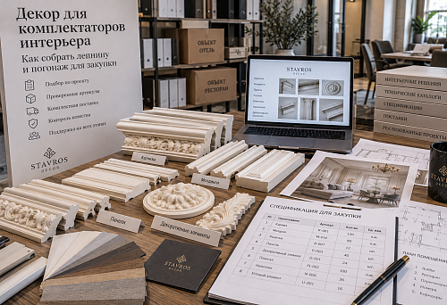
Architectural decor for architects begins with coordinates and junctions. First, axes, elevations, installation planes, and profile paths are defined. Then sections are checked, actual products are selected, and details are developed. The catalog provides components, while the working documentation explains how they form the interior.
This sequence allows the stucco to be coordinated with doors, panels, ceiling, furniture, and engineering systems before procurement. The output should be a set in which the elevation drawing, section, product code, and quantity describe a single solution.

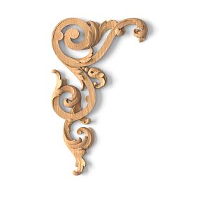
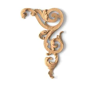

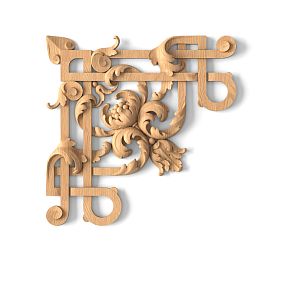
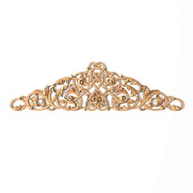
Start with the architectural line
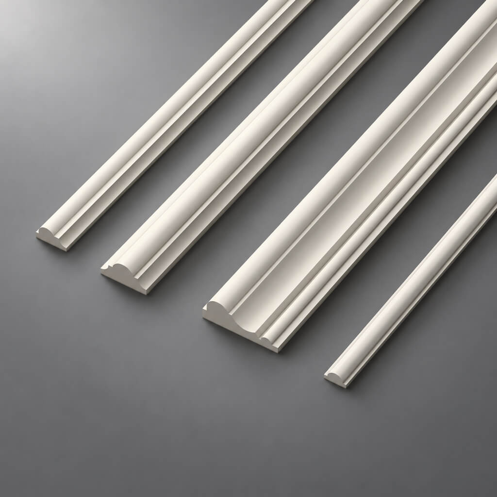
Molding can support the top of a doorway, separate the lower part of a wall, or form a field around a headboard. For each case, the role of the line is determined first. The profile is selected with this function, viewing distance, and neighboring elements in mind.
On the plan, openings, columns, niches, and built-in furniture are marked. On the elevations, the main horizontals and verticals are set. If the top of the frames must coincide with a specific portal line, this is tied by dimension or elevation mark rather than left to visual assumption.
Architectural stucco for interiors becomes part of a system when every line has a beginning, continuation, and completion. An isolated choice of a beautiful profile does not solve these issues.
Architectural decor for architects: the role of elements in the assembly
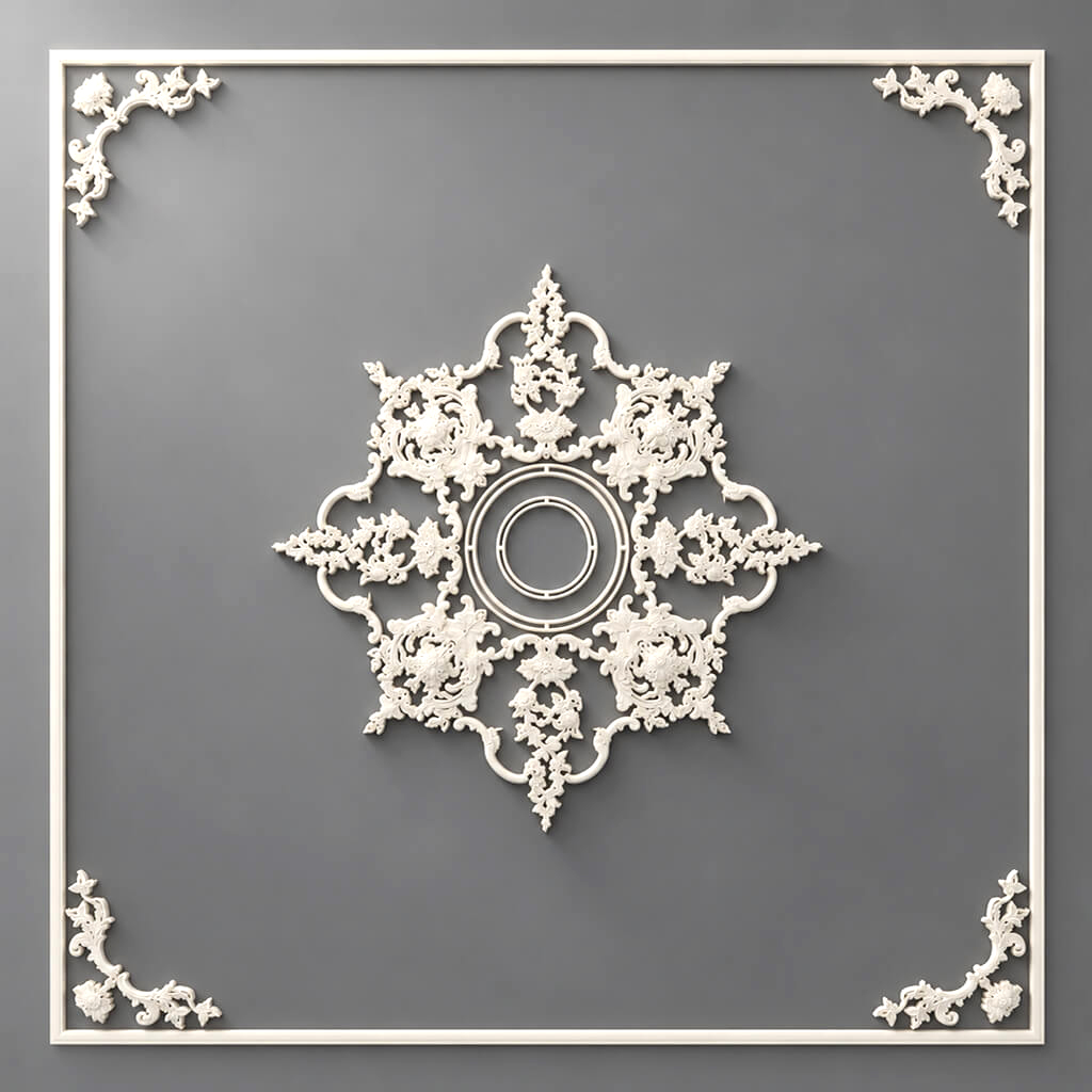
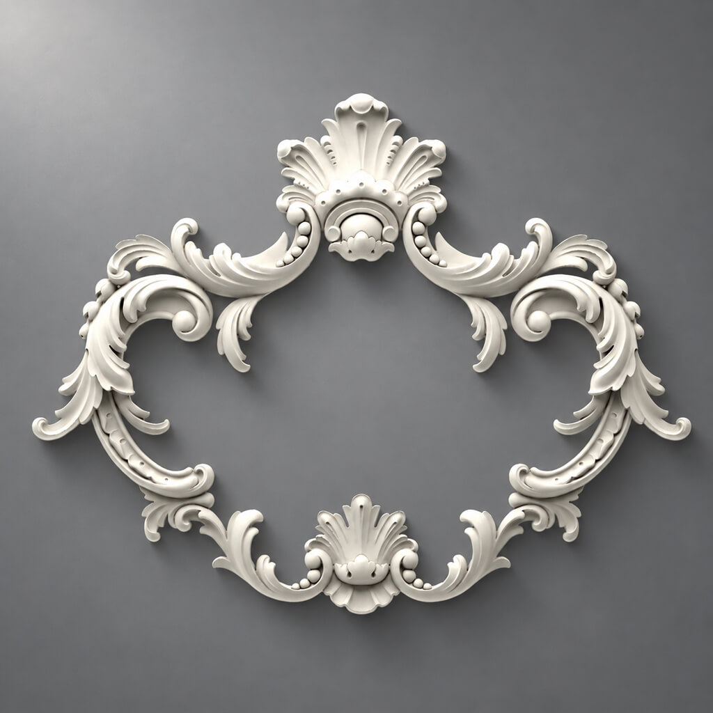
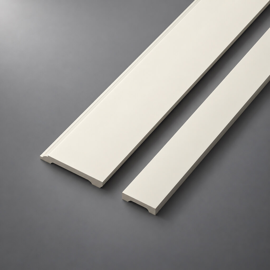
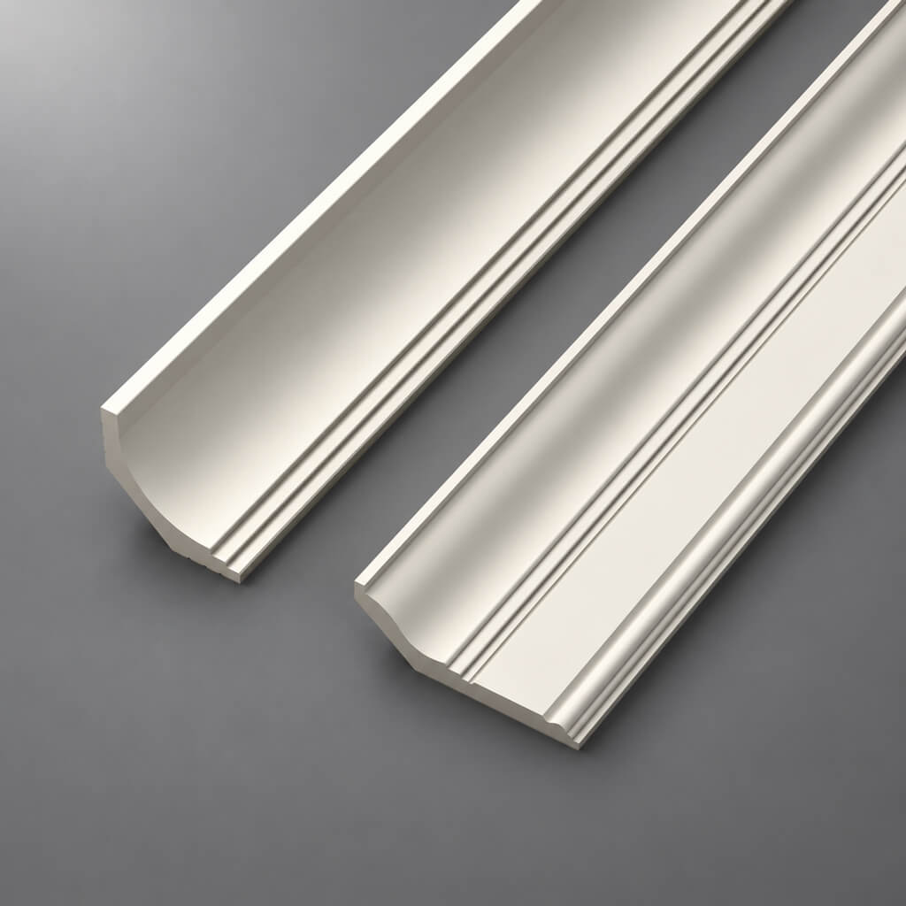
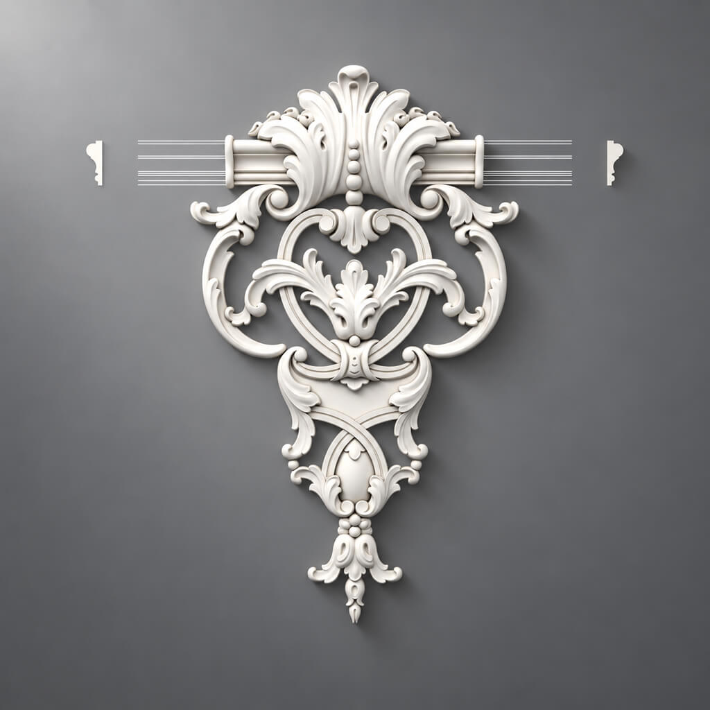
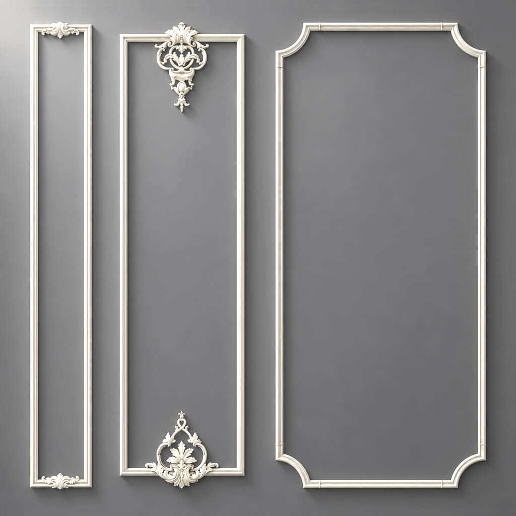
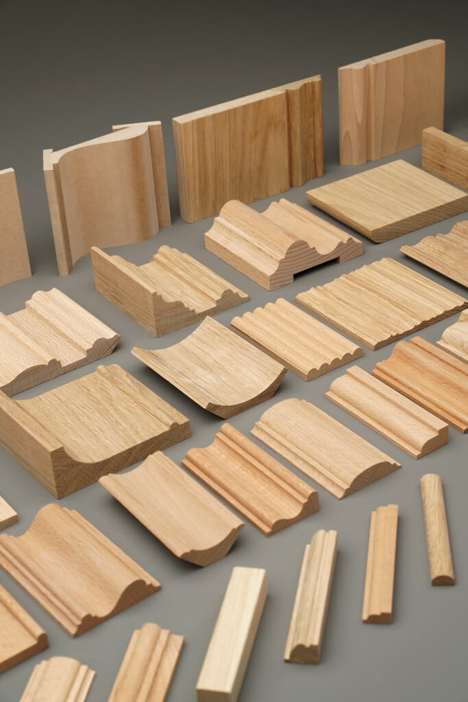
Linear trim forms extended contours: moldings, cornices, baseboards, and friezes. Individual pieces highlight a center, corner, or local accent. Pilasters, capitals, and portal elements define larger architectural divisions.
This functional separation helps determine the order of work. For a wall frame, the contour and junctions are decided first, then the ornament is added. If the composition is built around a large rosette or portal, their dimensions are coordinated with the profiles at the same time.
When selecting, . Clear lines, created using modern technologies, emphasize the strict aesthetics of the room. Each decorative element harmoniously fits into the overall concept, creating a sense of order and thoughtfulness. check the function of a specific part. A decorative bracket, column, or overlay does not become a load-bearing element just because of its name. Their application and fastening must correspond to the selected product and the project task.
Our factory also produces:


Set axes and elevation marks
Architectural moldings are tied to a stable coordinate system: the axis of the opening, the center of the composition, the edge of a panel, or an agreed elevation mark. A dimension from a random piece of furniture is unreliable if its position may still change.
It is important to specify from which surface the measurement is taken. An elevation mark from the finished floor and a dimension from the structural floor base refer to different levels. Similarly, a dimension to the finished wall differs from a dimension to its base when finishing layers are present.
The drawing explains what the line refers to: the profile axis, the outer edge of the frame, or the inner contour. If only "frame 1000 mm" is indicated, the installer should not independently choose the measurement base. The difference affects the field area and adjacent clearances.
For example, for a conventional rectangular frame, the outer width is 1000 mm. With a profile width of 20 mm on each side, the inner field is 960 mm. If the profile is replaced with a 35 mm wide variant while keeping the outer dimension, the field decreases to 930 mm. This calculation assumes a simple frame without additional corner pieces. When a mirror or panel of a specified size is placed inside, the change already affects the adjacent product. Therefore, the project determines which contour is fixed and which may change during selection.
Get Consultation
Establish the installation planes
A single junction may involve a wall, a shim, a panel, a casing, and the back surface of a molding. To check the protrusions, a common reference plane is chosen and the position of each element relative to it is shown.
A conventional example: the front surface of the panel is 20 mm from the reference wall. The installation plane of the profile is offset by 8 mm, and its maximum depth is 12 mm. The most protruding point will be at a distance of 20 mm — in the plane of the panel. But if the depth of the edge adjacent to the panel is 4 mm, this edge will be at a distance of 12 mm. An 8 mm difference will remain at the junction.
All dimensions in the example are conventional. It shows why matching maximum overall dimensions does not prove that the contact surfaces match. For the junction, a local section is needed.
The offset of the installation plane is interpreted through the structural layers of the junction. The base, shim, and finish must be shown with their design dimensions and purpose. Before installation, the actual position of the surface is checked. If it differs from the assumed one, a method of preparation is determined or the solution is adjusted, rather than simply shifting the decorative line. Otherwise, one frame will retain its outer shape but lose its alignment with the adjacent portal and panels.
Determine the allowable section, then look for the product
Before choosing an article number, it is useful to determine the allowable width, depth, and position of the profile in the junction. This is a search area, not a drawing of an imaginary product. After selecting a real model, the junction is refined according to its geometry.
For example, two conventional profiles 40 mm wide and 8 or 24 mm deep will occupy the same strip on the drawing but will protrude from the wall differently. The shadow, adjacent junctions, and the ability to place the profile near an opening door will change.
In the of polyurethane moldings compare cross-sections and available versions. If no suitable product exists, they adjust the agreed solution or separately develop custom manufacturing for the project. An arbitrarily stretched model does not confirm that such a profile can be purchased.
A single item code may have several sizes
In the product card MLDPU-027 options 14 × 9 × 2600 and 20 × 12 × 2600 mm in polyurethane are specified. Therefore, the project record must capture the selected size together with the item code.
The letter designations A, B, C, and L are read according to the diagram of the specific product. For a linear profile, they may describe width, depth, and length; for a piece part, the set of dimensions will be different. The meaning of each letter cannot be transferred between different groups without verification.
Moldings for architects are also evaluated by the back surface and the available attachment area. The maximum relief depth does not describe the contact area with the base and does not determine the installation technology.
How to coordinate a molding and a door casing
First, they decide whether the frame fits flush against the casing or maintains a separate offset. Then they check the position of the front surfaces, the profile edge, and the intended joint.
A molding protruding in front of the casing is not always a mistake: it may be part of an intentional three-dimensional composition. The mistake is to get it accidentally, without a finished end and a clear transition. Such a result is especially noticeable under side lighting.
The detail drawing shows the actual casing, wall finish, and profile. They check the opening of the door leaf and the position of the handle if they end up next to the decor. To buy polyurethane wall moldings, it is not enough to know the width of the free wall section: the entire detail near the door must be checked.
Every line must have a planned termination
The line can be finished with a machined end, a short return to the wall, an abutment to the portal, a coordinated end piece, or a deliberate break. The decision depends on the profile shape and the visibility of its termination.
A short return, or turn-back, closes the visible termination by adding an extra section of profile. Its geometry, size, and feasibility of manufacture are checked separately. Not every relief allows a neat short piece to be made with a standard cut.
When selecting Decor for Molding, clarify the purpose of the product. A flat decorative corner of the frame should not automatically be used for a turn between walls. The elevation drawing indicates the type of termination, while the section shows its construction and position.
Internal and external corners are checked separately
An internal corner requires a coordinated continuation of lines and a joint that accounts for the actual geometry of the walls. An external corner additionally reveals the volume of the profile: its projection is visible from several directions and may fall within a contact zone.
One must not assume that all corners of a room are exactly right-angled. The design sets the required geometry, and before manufacturing the parts, the actual conditions and the method of bringing them to the design are checked. The discrepancy should not be quietly transferred to the width of the decorative frame.
For a relief profile, check how the characteristic lines of the section meet. For ornament, the pattern is additionally assessed. The front view often hides a problem that is clearly visible in section or in a trial joint.
How to run a profile through a niche
In a niche, first determine which plane the decor follows: the outer surround, the reveal, or the back wall. Then show the turns, depth, and terminations. A single conventional rectangular symbol does not describe the entire path.
On short sections, check whether there is still room for a whole profile and the necessary joint. Light inside the niche can emphasize a step or an exposed end that is almost invisible under general lighting.
If a niche has a curved section, the feasibility of bending is confirmed for a specific model, direction, and radius. Not every polyurethane decorative element can be considered flexible. If the required configuration is not confirmed, the geometry of the solution is revised before purchase.
What happens to the horizontal line at the portal
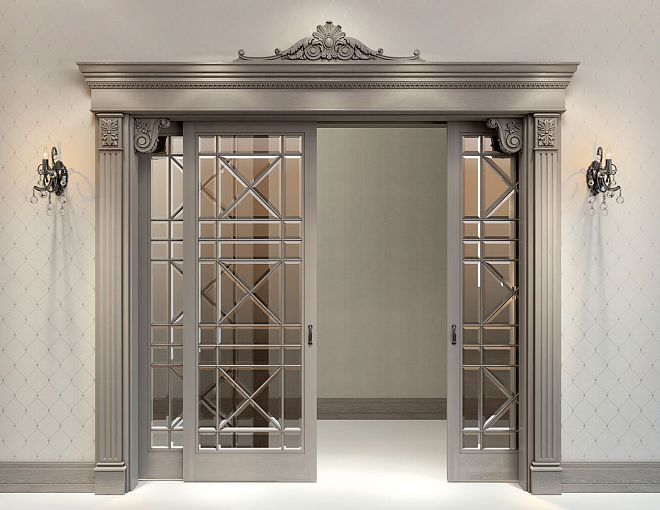
When meeting a door portal, the line may stop, turn toward the wall, continue along its elements, or give way to independent trim. The architect chooses a strategy for the entire group of similar openings.
Continuing through the portal requires checking several planes and sections. Matching elevations does not yet mean that the parts will join without a step. If the lines remain independent, the offset and nature of the break are recorded.
For typical assemblies, it is convenient to assign designations U-01, U-02 and reference them on the elevations. At the same time, each opening is checked for the applicability of the typical solution. A different casing or reveal depth may require a separate part.
How to join the skirting board with the casing and panel
At the door casing, the thickness of the skirting board is checked specifically at the junction. If the skirting board protrudes, an end piece, transition element, or another agreed solution is provided. Cutting "to fit" does not replace the chosen assembly principle.
Near the panel, different schemes are possible: the skirting board runs in front of it, adjoins its edge, or enters the lower termination of the panel system. The section must show the installation planes and the assembly sequence. Otherwise, one part may block the installation location of another.
Before buying a skirting board from the section STAVROS skirting boards, check the specific material and configuration. They cannot be determined by the category name alone. The specification must correspond to the product that is actually intended for the selected assembly.
The cornice is coordinated in two directions
A ceiling cornice occupies space along the wall and along the ceiling. It is checked in the installation position: where the lower edge runs, how far the element extends onto the ceiling, and which surfaces serve as support.
The junction takes into account the curtain niche, built-in wardrobe, lighting, and ventilation elements. The catalogue profile depth alone does not answer the question of whether access to equipment will be preserved or whether the adjacent facade will open.
Choosing Ceiling Molding, the material is also recorded. This section presents HIWOOD polystyrene models, so all products cannot be called polyurethane. To buy a cornice for an approved project, the full specification and a verified installation position are required.
Ceiling decor is checked together with the engineering services
The combined ceiling plan shows luminaires, grilles, sensors, fire sprinklers, and access hatches. The decorative contour must not obstruct maintenance or disrupt the approved operation of the engineering system.
In case of a conflict, the decision is made together with the designer responsible for the relevant system. Moving a device arbitrarily for the sake of moulding symmetry is unacceptable as a design approach. The ceiling geometry and equipment layout must be coordinated in the documentation.
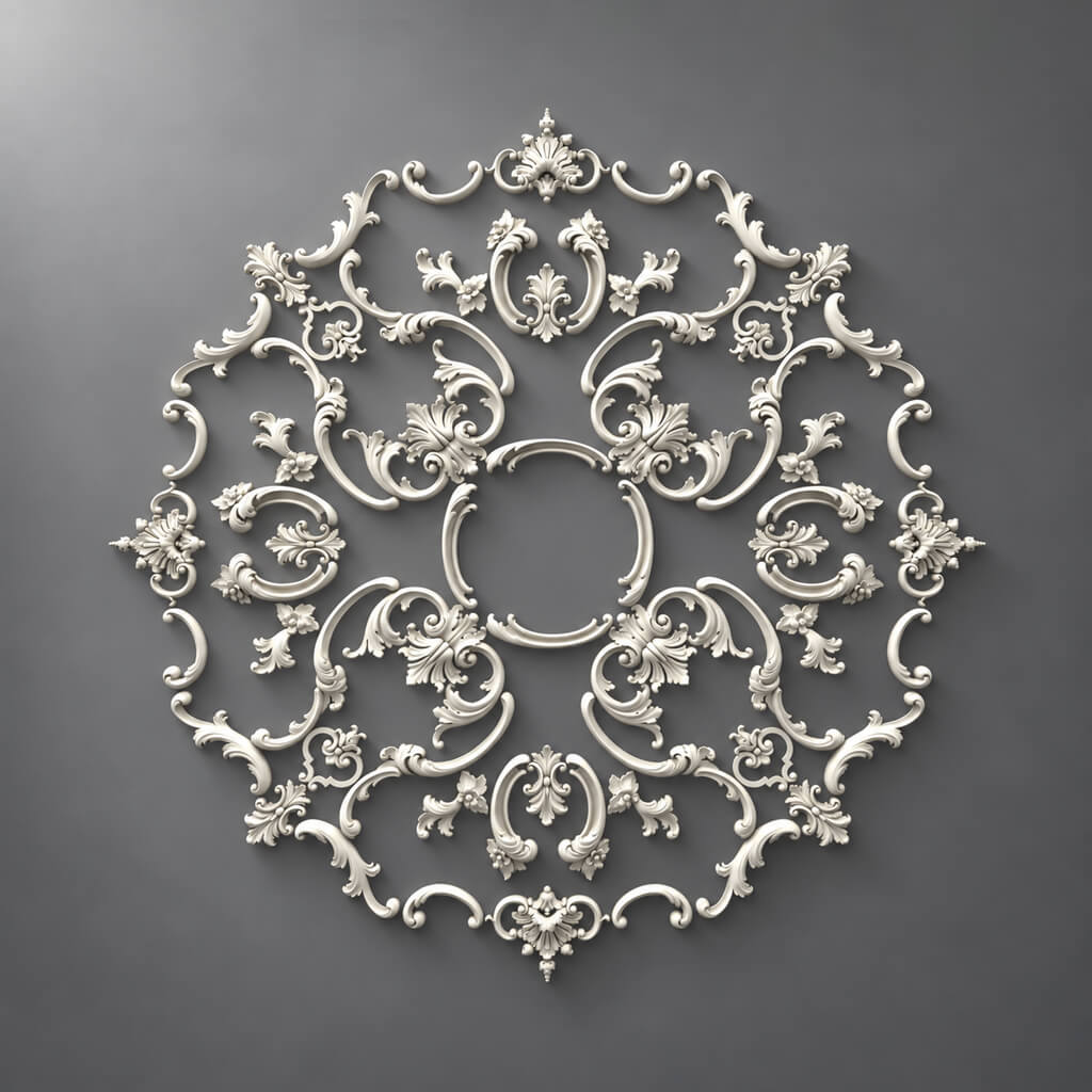
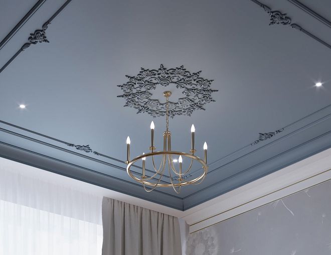
Decorative rosettes and cover plates are also checked together with the luminaires and their fixings. The presence of an opening or a beautiful central composition does not mean that the decorative element can bear the suspension load. The luminaire fixing is designed separately according to its installation conditions.
Build a hierarchy of profiles and ornament
Usually it is sufficient to define the main profile, the secondary contour, and local accents. They are designated, for example, M-01, M-02, and H-01. Several nearly identical mouldings make sense to keep only when the difference in their tasks is clear.
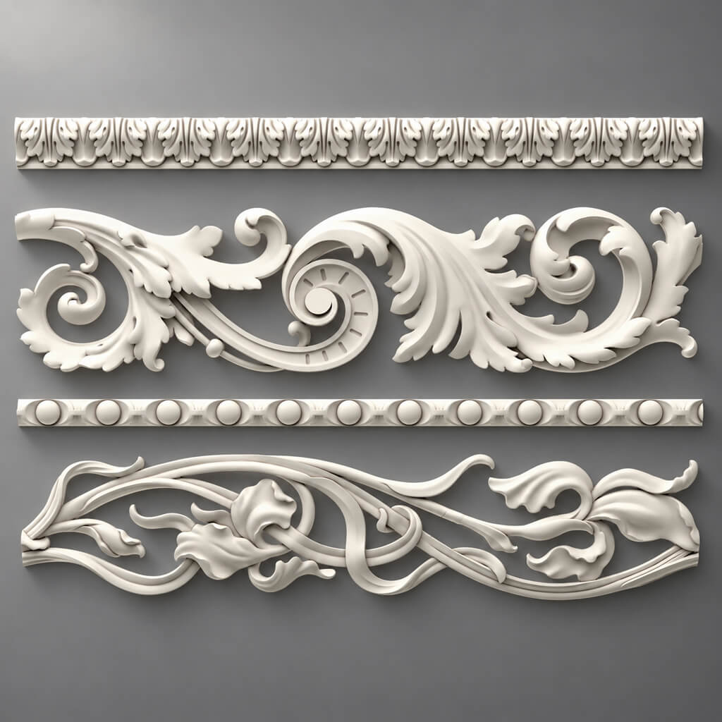
A smooth or restrained profile organizes a repeatable line. Ornamental polyurethane moulding requires additional work with the pattern. Check the repeat — the step at which the motif repeats, its position relative to the center, and the allowable cut points.
Piece molded decoration made of polyurethane are coordinated with this frame. If a large central element defines the entire composition, it is selected in parallel with the profiles. The rule "overlays always last" should not interfere with checking interdependent dimensions.
When wooden moulding is needed at the junction
The material is determined together with the base, the joining method, and the finish. For wooden elements, the species is specified, while MDF is indicated separately as a panel material. The same paint color does not make these versions interchangeable.
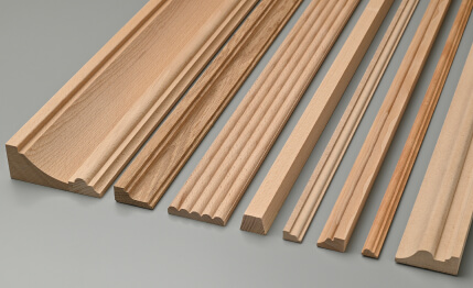
Section wooden trim helps to choose profiles, and the catalog solid wood trim — related products for a specific task. Dimensions and commercial length are checked on the selected product page, and are not applied to the entire material.
Before deciding to buy wooden moulding, the surface condition and subsequent finish are agreed upon. At the boundary with a polyurethane part, both the geometry and the joining technology are checked. The ability to cover everything in one color does not yet confirm that a single installation solution is suitable for different materials.
Link the layout, the assembly, and the actual SKU
The layout keeps a short design tag, while the full description goes into the schedule. Each tag must unambiguously lead to the selected variant and the corresponding assemblies.
| Data on the drawing | Linked data in the schedule |
|---|---|
| M-01 | Manufacturer, SKU, material, and size |
| Axis and elevation | Measurement base and profile position |
| U-01 | Junction section and termination method |
| Wall or zone number | Application location and quantity calculation |
| Finish designation | Coating and approved sample |
| Sheet revision | Current version of the decision |
Show the start, end, and transitions explicitly. A long commercial name next to each line is not required, but the link to the product must be preserved. If one model is used in several assemblies, these assemblies should not automatically be considered identical.
What a working assembly description should contain
A single section contour is not enough if it is impossible to understand from it how to assemble the parts. The working assembly shows the base, adjacent layers, the position of the profile, the intended fastening, and access for performing the work. Installation materials are selected for compatibility with the product, the base, and the conditions of use.
| Check | What needs to be determined |
|---|---|
| Installation base | Prepared surface and its position |
| Sequence | Which parts are installed before the others |
| Connection | Joint, termination, transition, or designated gap |
| Control | Verified dimensions and accepted requirements |
| Maintenance | Access to removable elements and equipment |
| Application area | Premises and conditions for which the assembly is designed |
For example, the trim may obstruct the fasteners of a removable panel, even though all dimensions will align in the final position. Such a conflict is only detected when checking the assembly and maintenance sequence. It is resolved before manufacturing the parts: the layout, connection method, or profile position is changed with appropriate coordination.
Where DWG and 3D models are needed
Drawings and 3D models of STAVROS architectural decor are used as source materials. The compliance of a specific file with the selected article and finish is verified before inclusion in the project. The availability of a shared archive does not confirm that the required part has already been reviewed.
A 3D model helps evaluate scale, trajectory, and intersections. Working sections show installation planes, local relief, clearances, and connections. These are complementary ways of describing: a high-quality volumetric model can contain accurate geometry, while the DWG format alone does not guarantee the completeness of an assembly.
After import, check the units, scale, and orientation. Stretching the profile to match a line in the visualization is not allowed without changing the actual design. The image must correspond to the product that will be ordered.
Check the characteristic assembly at full size
Through Product samples a preliminary check is arranged; the availability of a specific sample is clarified separately. For a complex junction, an assembled fragment with the base, adjacent part, and specified finish is useful.
Evaluate the overhang, local joint, exposed ends, color, and light-and-shadow. If the project includes side lighting, its scenario is reproduced on a test area. Otherwise, a defect invisible under diffused light will be discovered after the finish is completed.
The approval is recorded with the verified composition and conditions. An accepted color does not automatically mean an accepted fastening, and an approved profile does not confirm all possible variants of its installation. The physical sample is kept together with the designation of the assembly and revision.
It is useful for the contractor to make a trial assembly using the issued materials. If oral clarifications from the architect are constantly needed for the result, the documentation is supplemented. Record which dimensions are measured, from which points the appearance is evaluated, and under what lighting the finish is compared. Accuracy requirements are agreed upon for specific products and works; a universal numerical tolerance is not assigned here. A re-check is carried out after the comments are corrected, so that the final version is approved, not its intermediate state.
Record the decision and manage replacements
After approval, the item code, version, dimensions, material, and finish are locked in. Any replacement goes through an assessment of its impact on adjacent elements, drawings, quantities, and placed orders.
A change in width may require a new layout of frames, a change in depth may require a new junction with the architrave, and a different length may require recalculating the battens. Even a visually similar model is not considered approved until the relevant checks are completed.
The previous version is retained, and the new one is distributed to specific zones. The reason and approval are indicated in the log. If part of the decor has already been installed, the boundary of application of the old and new solutions is recorded, so that installation and subsequent repair rely on actual data.
Convert assembly geometry into the quantity of products
For each profile, a list of cut lengths, angles, ends, and piece elements is compiled. Lengths are measured along the accepted base. The cutting plan is then determined taking into account the commercial length and the required cuts.
A conditional example: three simple frames with an outer size of 1800 × 600 mm require six long and six short sides. With a profile length of 2600 mm, two 1800 mm segments do not fit together, so at least six profiles are needed. Each can accommodate 1800 and 600 mm: 2400 mm in total. If the conditional total losses of 20 mm per profile are sufficient for the selected cuts, the set fits into six profiles, leaving a separate reserve.
Actual losses are verified against the manufacturing technology. Special angles, returns, and pattern repeat change the calculation. Installation and repair reserves are accounted for separately, without assigning the same percentage allowance to all projects.
When the project is ready for purchasing
Before submitting the request, the consistency of the documents is checked. For each item, the axes and elevations, installation planes, cross-section, ends, article number, finish, surface treatment, and quantity must be defined. An unresolved junction cannot be covered by a note to "clarify during installation" if the choice of product depends on it.
Open questions are linked to specific items and responsible parties. If the architrave has not yet been confirmed, this may delay only the assemblies related to it, not the entire decor of the facility. But such a boundary is determined by the project dependencies. The readiness of the overall list of goods does not mean that every line is ready to order.
To buy moldings and cornices or order architectural decor according to a project, a schedule with clear units is sent to the supplier: whole profiles, pieces, or sets. The composition of the set is clarified so that the elements included in it are not counted twice.
The price of polyurethane stucco is compared for identical finishes and delivery terms. Preparation, finishing, packaging, and delivery are included in the agreed scope. The final cost is determined by the verified quantity, not by the approximate wall perimeter.
Where to buy decor for an architectural project
В STAVROS architectural decor catalog select product groups corresponding to the developed units. To buy polyurethane molding, go to the section polyurethane molding, then confirm the specific designs and the full scope of supply.
Section for designers and architects contains information about professional collaboration and project materials. The request to the supplier is accompanied by item codes, dimensions, quantities, and required deadlines. If a unit depends on an unconfirmed specification, the relevant data is obtained first.
Architectural decor for architects becomes a ready-made solution when the catalog is linked to the working documentation. A profile has a specific installation plane, a line has a beginning and an end, and a junction has a verified cross-section. Then procurement reproduces the project, and installation relies on approved units.