















Article Contents:
- Wooden curtain rod KZ-015 61×87 mm: which dimension is critical next to the track
- Why 61 mm is secondary here
- 300 mm to the near edge of the busbar
- 300 mm to the axis
- 300 mm to the far edge of the track
- Conditional example
- Why one 87 mm strip is not enough
- When instead of KZ-015 you should check KZ-016
- KZ-015 made of MDF under enamel: when it is better to visually remove the cornice
- Wall 5200 mm: beech or oak KZ-015 2400 mm
- How to choose the location of the longitudinal joint KZ-015 near the track
- Track end falls near an internal corner: which element to calculate first
- If the track is not parallel to the wall
- Track with several types of fixtures: check the largest one
- KZ-015 and stretch ceiling: first the base, then the decorative profile
- What to do if KZ-015 fits the geometry, but the light on the wall becomes worse
- How to choose the material of KZ-015 after checking the track
- What to send to the STAVROS manager before ordering
- Final procurement specification for KZ-015
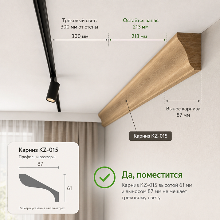
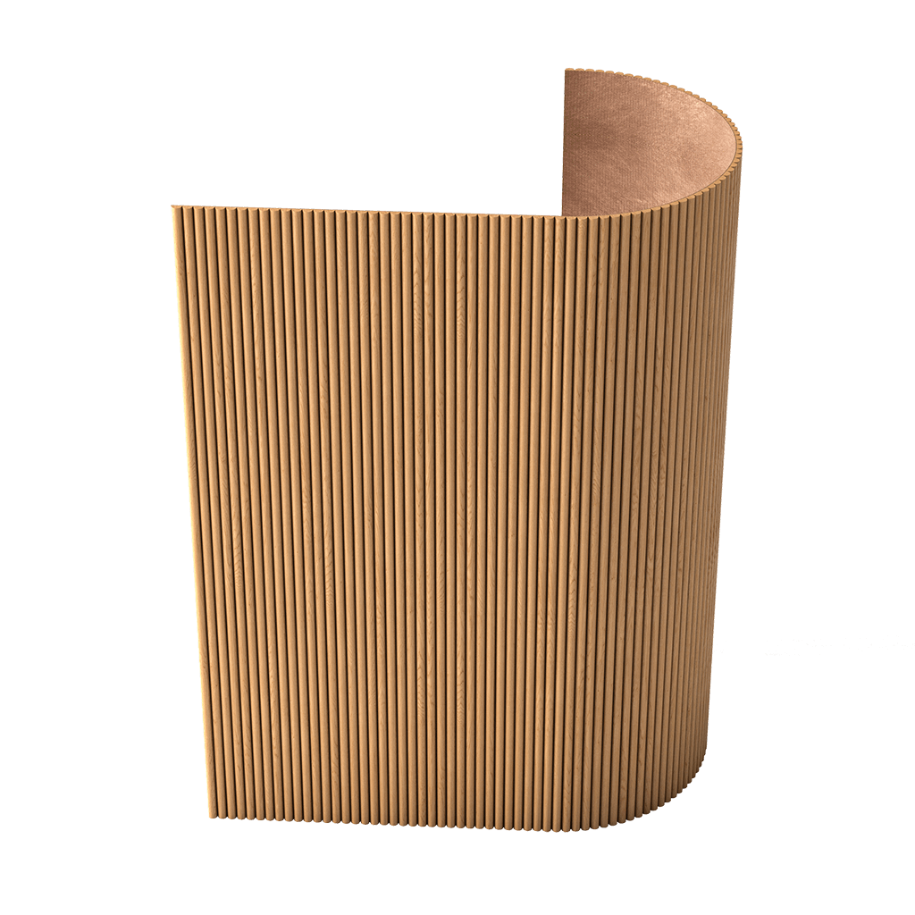
The track busbar is already installed, and changing its position is expensive and undesirable. After the electrical work for the upper line of the room, KZ‑015 was chosen — a deep wooden cornice 61×87 mm. On the plan, 300 mm is indicated between the wall and the track, so the first arithmetic seems calm:
300 − 87 = 213 mm.
But 213 mm is only a preliminary geometric remainder, not a proven working gap between KZ‑015 and the track light. It all depends on what exactly the designer called “300 mm”:
-
distance from the wall to the busbar axis;
-
distance to its near edge;
-
distance to the far edge;
-
distance to the axis of the installed adapter or luminaire.
Besides the track itself, the adapter housing and the maximum rotation of the luminaire head toward the wall must be considered. If in the working scenario the spotlight extends toward the cornice further than the busbar itself, its edge becomes the critical point.
Therefore, the direct answer is:
KZ‑015 with a 87 mm offset can fit with a track marked on the plan as 300 mm from the wall, but you cannot buy a cornice using the formula 300−87. First, determine the base of the 300 mm dimension, measure the track width and the maximum dynamic extension of each luminaire toward the wall, then check the assembly with a full-size template of 61×87 mm.
Before ordering, you need to:
-
mark the wall line;
-
determine to which point of the track the 300 mm is given;
-
measure the actual width of the busbar;
-
measure the adapter;
-
rotate the nearest luminaires to the maximum working position towards the wall;
-
determine the point of the entire lighting system closest to the wall;
-
mark off the real 87 mm KZ‑015 along the ceiling;
-
check the static and dynamic clearance;
-
make a template 61×87 mm;
-
only then choose the material and quantity.
If the profile is not yet approved, you can Buy wooden ceiling baseboard after comparing the actual overhangs. If KZ‑015 is chosen, then a calculation of the specific 87‑mm dimension is needed.

Wooden cornice KZ-015 61×87 mm: which dimension is critical near the track
The current KZ‑015 card confirms:
| Execution KZ‑015 | Size, mm | Price at the time of check | Status |
|---|---|---|---|
| MDF | 61×87×2600 | 2,240 RUB | in stock in SPb |
| Beech | 61×87×2400 | 6,170 RUB | in stock in SPb |
| Oak | 61×87×2400 | 9,260 RUB | in stock in SPb |
Price and availability change; the card must be rechecked before payment.
In the STAVROS comparison material, size KZ‑015 is interpreted as follows:
-
61 mm — height along the wall;
-
87 mm — projection along the ceiling.
It is exactly 87 mm that is used in calculating the conflict with the track. The first product mention is — Wooden cornice KZ-015.

Why 61 mm is secondary here
The height along the wall determines the scale of the top line, adjacency to portals and moldings. But the track is located on the ceiling, so mechanically 87 mm is more important.
Why the length of 2600/2400 mm is also important
MDF has a length of 2600 mm, beech and oak — 2400 mm. After resolving the light node, this affects joints, leftovers, and the order map.
Our factory also produces:


Wooden ceiling molding and track lighting: why you can't just calculate the distance to the axis
Let us denote:
-
Daxis— distance from the wall to the track axis; -
Wtrack— width of the busbar; -
P— ceiling overhang KZ-015, i.e., 87 mm; -
Cstatic— static clearance from the cornice to the nearest edge of the track.
If 300 mm is given to the axis:
Cstatic = Daxis − P − Wtrack/2.
When Daxis = 300 mm:
Cstatic = 300 − 87 − Wtrack/2.
Bye Wtrack not measured, no final figure.
Conditional example with a track width of 30 mm
This is only an arithmetic illustration, not a characteristic of your system.
The near edge is located:
300 − 15 = 285 mm from the wall.
Clearance after KZ‑015:
285 − 87 = 198 mm.
Conditional example with a track width of 40 mm
Near edge:
300 − 20 = 280 mm.
Clearance:
280 − 87 = 193 mm.
These examples show the method. The actual width needs to be measured.
Get Consultation
The track is placed 300 mm from the wall: three different calculations for KZ-015
300 mm to the near edge of the busbar
Static clearance:
300 − 87 = 213 mm.
300 mm to the axis
Need to subtract half the track width:
Cstatic = 300 − 87 − Wtrack/2.
300 mm to the far edge of the track
First:
Dnear = 300 − Wtrack.
Then:
Cstatic = 300 − Wtrack − 87.
With a nominal width of 30 mm:
300 − 30 − 87 = 183 mm.
If the plan is not signed, the installed track must be measured physically.
What needs to be added to the busway dimension
Static track — only the baseline. Next to KZ‑015 may protrude:
-
adapter;
-
connector;
-
power feed;
-
spotlight housing;
-
rotary hinge;
-
decorative part of the luminaire.
For each element, it is necessary to find the point closest to the wall in the working position.
Rotary head of a track luminaire: why a static drawing is insufficient
We introduce a parameter:
Rwall — the maximum actual overhang of the entire rotary head from the track axis toward the wall.
If 300 mm is given to the axis:
Cdynamic = 300 − 87 − Rwall.
Conditional example
Let the closest point of the luminaire in the working position be 90 mm from the track axis toward the wall.
Then:
300 − 87 − 90 = 123 mm.
Although a simple calculation without the luminaire showed 213 mm.
This does not mean that 123 mm is automatically too little. It means that this exact real figure needs to be checked against the luminaire and access.
How to make a full-size template for KZ-015 before purchasing
For a boundary node, a physical mock-up works best. Not a strip of paper 87 mm wide, but a profile that reproduces the working position of KZ‑015 in the wall-ceiling joint.
Simplest template
You can cut an L-shaped mock-up from:
-
thick cardboard;
-
foam board;
-
thin plywood;
-
MDF.
Dimensions of the control section:
-
61 mm along the wall;
-
87 mm along the ceiling.
The template is applied not only in one place, but across the entire area where the track approaches the wall.
Why one 87 mm strip is not enough
It only shows the ceiling overhang.
A full-size mockup simultaneously allows you to see:
-
the actual bottom line of the cornice;
-
shadow;
-
visual scale;
-
conflict with ventilation;
-
angle;
-
the curtain niche;
-
the end of the track.
What to check with the light fixture
After installing the template:
-
point the head down;
-
turn to the wall;
-
point along the track;
-
set up a realistic lighting scenario for the painting/curtains;
-
check the removal of the luminaire, if the system provides for it.
Hand check
Even without physical contact, make sure the installer has convenient access:
-
turn the head;
-
remove the adapter;
-
replace the luminaire;
-
clear the track.
If the cornice does not touch the luminaire, but the hand does not fit for service, the assembly is still inconvenient.
Why 213 mm of free space may be sufficient in one section and insufficient in another
Preliminary remainder 300−87=213 mm has no universal meaning.
In one section, there is only a narrow busbar nearby. In another, there is a large rotating head. In the third, there is the end of the track with a power feed element.
Section without a luminaire
Here, only the geometry of the track itself and the adapter is critical.
213 mm to the nearest edge of the busbar may look free.
Section with compact head
The actual dynamic clearance is smaller, but it can still remain convenient.
Section with large spotlight
The head can take up a significant part of the free field.
End of track
The power or connecting element can be larger than a regular line.
Conclusion
You cannot check one arbitrary meter of track and apply the result to the entire room. The most protruding element of each type is checked.
Where to measure the distance between KZ-015 and the track
After installing KZ‑015, the control geometry must have clear reference points.
Point 1. Edge of the cornice
Not a wall or a conditional profile axis, but the point KZ-015 on the ceiling closest to the track.
With correct orientation, this is an offset of 87 mm from the wall.
Point 2. Near edge of the busbar track
Needed for static clearance.
Point 3. Near point of the swivel head
Needed for dynamic clearance.
Point 4. Service zone
The space where a hand or tool works with the luminaire is assessed separately.
Convenient note on site
For example:
-
wall → track axis: 300 mm;
-
track width: ___ mm;
-
wall → near edge of track: ___ mm;
-
KZ‑015: 87 mm;
-
static clearance: ___ mm;
-
maximum luminaire extension toward the wall: ___ mm;
-
dynamic clearance: ___ mm.
After such a table, the ambiguity of "three hundred millimeters seems enough" disappears.
KZ-015 and the 20–30 cm reference to the track: how to apply it correctly
In the general STAVROS article on ceiling decor and track lighting, a reference of 20–30 cm between the track and the cornice is given. For our task, it cannot be turned into a construction standard.
This is a practical design guideline that helps:
-
do not press technical light against a large cornice;
-
maintain a visual pause;
-
leave room for adjusting the heads.
What exactly to compare with 20–30 cm
The strictest option is the actual free clearance between the edge of KZ-015 and the working dimension of the luminaire, not just between the wall and the track axis.
Example
If 300 mm is given to the axis, the track is conventionally 30 mm, then to its near edge:
285 mm.
After KZ-015:
198 mm.
This is already slightly less than 20 cm.
If the luminaire protrudes even further toward the wall, the free field will decrease more.
Why 19.8 cm does not automatically mean a prohibition
Because 20–30 cm in the STAVROS article is not a mandatory SNiP/SP standard.
Need to evaluate:
-
specific luminaire;
-
real angle;
-
visual composition;
-
service.
Why even 25 cm may be insufficient
If a large head rotates toward the wall and physically enters this field.
That is, the reference point does not replace the kinematic test.
Light beam and KZ-015: there may be no physical contact, but the visual conflict remains
Track lighting affects the cornice not only with its housing.
When directing the spotlight towards the wall near KZ-015, the following may appear:
-
a sharp shadow from the 87-mm offset;
-
light spill on the profile;
-
a bright stripe;
-
uneven wall illumination.
When a deep shadow is useful
If KZ-015 should be perceived as an architectural profile.
When the shadow interferes
If the spotlight is intended for:
-
paintings;
-
curtains;
-
wall panel,
and the cornice overlaps part of the light flow.
How to check
Install temporary template KZ‑015 and turn on the light in evening mode.
You need to look not only at the distance, but also at the light pattern.
Why this is not a reason to automatically increase the gap
Sometimes shifting the spotlight angle solves the problem without changing the track or cornice.
But if the working light scenario requires direction toward the wall, the cornice must be checked in that position.
If KZ-015 does not fit: you cannot trim its overhang from 87 to 60 mm
KZ‑015 is a ready-made profiled section. Reducing the ceiling part by tens of millimeters changes:
-
proportion;
-
face drawing;
-
fit;
-
corner cuts.
You cannot perceive 87 mm as "extra wood reserve."
What to do instead
-
shift the track, if still possible;
-
change the orientation/type of the light fixture;
-
choose a more compact cornice;
-
change the ceiling composition;
-
refuse the cornice on a specific wall only as a conscious design decision.
Why locally cutting off only near the spotlight is a bad idea
The cornice will get a change in cross-section over a short section.
This will look like a technical recess, not an architectural line.
When instead of KZ-015, check KZ-016
A full comparison already exists, so only a technical conclusion is needed here.
KZ‑015:
61×87 mm.
KZ‑016:
54×54 mm.
Difference in ceiling overhang:
87 − 54 = 33 mm.
If 87 mm creates a conflict, these 33 mm may be decisive.
For a detailed selection, use the material KZ-015 or KZ-016.
Example with a 300 mm track to the near edge
KZ‑015:
300 − 87 = 213 mm.
KZ‑016:
300 − 54 = 246 mm.
Difference in free field:
33 mm.
Why you cannot automatically switch to KZ-016
Because it is a different profile in terms of scale.
Technically it is more compact, but design-wise it may be too small for the room.
Wooden KZ-015 made of oak or beech next to a black track
The material of the cornice does not change the 87 mm projection, but it greatly affects the visual conflict with light.
Oak + black track
Contrast pairing:
-
warm natural wood;
-
technical black line.
Works well if the interior deliberately combines classic joinery and modern lighting.
Beech under enamel
Can be painted to match the ceiling/wall color and visually hide the cornice.
Oak for tinting
Light from swivel spotlights emphasizes the pores and texture of the wood.
For this solution, a natural wood plinth cluster is natural, but the KZ-015 itself remains a cornice.
Why the black track cannot be assessed only during the day
In the evening, it becomes an active light line. Need to check the cornice:
-
with the heads on;
-
with the general light off;
-
with the real direction of light.
KZ-015 from MDF under enamel: when the cornice is better to hide visually
If the track should remain the main graphic element of the ceiling, MDF KZ‑015 can be painted in the color of the ceiling or wall.
Advantages:
-
the cornice retains its architectural volume;
-
the color contrast decreases;
-
the black track line reads more strongly.
MDF 2600 mm
An additional advantage is the greater length compared to beech/oak at 2400 mm.
On a long wall, this can reduce the number of joints.
What to check after painting
Side light from the track can reveal:
-
orange peel;
-
uneven joint;
-
difference in gloss;
-
local puttying.
Therefore, a test light test is needed after the finish.
KZ-015 2600 or 2400 mm: how the track affects the cutting plan
At first glance, the length of the cornice is not related to light. In practice, it is near the end of the track that often appears:
-
an additional angle;
-
an interruption of the cornice;
-
a short section;
-
a finished end;
-
a zone where a longitudinal joint is especially undesirable.
Therefore, the KZ-015 map is built after the track geometry is resolved.
MDF 2600 mm
The advantage is a longer whip.
It can:
-
cover a 2500 mm wall with one piece;
-
reduce the number of joints;
-
give more freedom near the corner.
Beech/oak 2400 mm
Planks are 200 mm shorter.
On walls 2450–2600 mm this changes the picture: a solid piece is not possible.
Why can't you first choose the material by color and then calculate the same way
Because the transition:
2600 → 2400
can increase the number of purchased planks.
Material, length, and joint layout are linked.
Wall 5200 mm: how many KZ-015 to buy from MDF
Pure arithmetic:
2600 + 2600 = 5200 mm.
Therefore, I want to order exactly two planks.
But we need to check what "wall 5200" means.
Scenario 1. Straight line with two simple open ends
If both parts can be trimmed minimally and the central joint is acceptable, two planks are potentially suitable.
But the allowance:
0 mm.
Any refreshing of the end reduces the useful length.
Scenario 2. Internal corners on the left and right
Both end pieces get angled cuts.
It is necessary to understand:
-
at which point the 5200 mm is measured;
-
how much material is required for the actual long points;
-
whether the central joint can be placed exactly in the middle.
Scenario 3. The end of the track requires a separate short section.
For example, the cornice is decided to be interrupted 300 mm earlier or a special end is formed.
Then the original two parts no longer have to be 2600 each, the layout changes.
When a third MDF plank is justified
if:
-
two complex corners;
-
the joint must be offset;
-
one side requires a solid piece 2700+;
-
a reserve for error is needed.
But buying a third one automatically is also not necessary.
Wall 5200 mm: beech or oak KZ-015 2400 mm
Here, simple arithmetic immediately shows the shortcoming:
2400 + 2400 = 4800 mm.
Missing:
5200 − 4800 = 400 mm.
Therefore, the minimum length is three planks.
Possible map
-
plank 1 → 2400;
-
plank 2 → 2400;
-
plank 3 → 400 + reserve/other section.
But this is a very rough scheme.
More reasonable map
If the wall has corners and a neat central seam is needed, you can do:
-
1900;
-
1800;
-
-
Three pieces give 5200 mm.
Advantage — joints can be tied to the architecture.
Disadvantage — more connections.
When the third plank stops being an "expensive leftover"
If the room also has a short section:
-
1200 mm;
-
1600 mm;
-
1800 mm,
the leftover of the third plank can be used there.
Therefore, the entire room is considered as one map.
Example of a room: long wall with track + two short walls
Suppose, after measurements, segments KZ‑015 are obtained:
-
A = 5200 mm;
-
B = 1800 mm;
-
C = 1200 mm.
Total length:
8200 mm.
MDF 2600 mm
Mathematical minimum:
8200 / 2600 ≈ 3.15 → 4 planks.
Let's check the actual map.
Can be distributed:
-
plank 1 + 2 → wall A at 2600;
-
plank 3 → B 1800 + remainder 800;
-
plank 4 → C 1200 + remainder 1400.
Four strips are enough if zero allowance on wall A is acceptable.
Beech/oak 2400 mm
Overall minimum:
8200 / 2400 ≈ 3.42 → 4 strips.
But four may not work.
Wall A 5200 requires a minimum of three original strips.
After it, from three rods there may be a total of 2000 mm left, but fragmented.
For B = 1800 and C = 1200, you need to check the actual pieces.
For example:
-
A = 1800 + 1800 + 1600.
Remainders from three rods:
-
600;
-
600;
-
-
None covers B 1800 or C 1200.
Then you need:
-
3 planks on A;
-
1 on B;
-
1 on C.
Total 5 planks, although the total footage said "4".
Why this is stronger than regular division
Because the long wall "locks in" three rods and leaves awkward short remnants.
This is a typical practical cutting conflict.
How to choose the location of the longitudinal joint KZ-015 near the track
The longitudinal joint should not accidentally fall where track lighting emphasizes it.
Bad points
-
directly under the spotlight;
-
near the end of the track;
-
near the corner;
-
where the light runs along the cornice.
Good spots
-
less illuminated area;
-
above the cabinet;
-
above the curtain area;
-
where the architecture already has a vertical reference.
Why side light enhances the joint
Even a small step casts a shadow.
The closer the spotlight and the sharper the angle of light, the more noticeable the defect.
How to check before the finish
Assemble two strips dry and aim the nearest spotlight in the actual working position.
The end of the track lands near the inner corner: which element to calculate first
If the end of the busway is near a room corner, the following converge in one zone:
-
KZ‑015;
-
corner cut;
-
track end/termination;
-
a light fixture;
-
power feed element.
You cannot start with cutting the cornice.
Correct sequence
-
determine the 87 mm dimension KZ-015;
-
measure the near point of the track;
-
check the rotation of the luminaire;
-
check the supply/connecting element;
-
measure the actual wall angle;
-
make an angle template;
-
determine the length of the cornice;
-
only then cut.
Why the angle cannot be considered last
The miter cut changes the long point of the part.
If on a straight line the gap to the track was 210 mm, in the corner zone the actual geometry may look different.
Can KZ-015 be interrupted only on the track light section?
Technically, the cornice can be finished before the track, but then it is no longer a regular continuous ceiling contour.
When the interruption can be intentional
If there is:
-
a cabinet up to the ceiling;
-
portal;
-
column;
-
a niche;
-
another architectural element.
Then the cornice ends at a clear boundary.
When the interruption looks accidental
If KZ-015 simply ends 500 mm before the spotlight in the middle of an empty wall.
What is better
In this case, it is often more rational:
-
choose a more compact profile;
-
change the track;
-
rework the entire wall line.
How to design an open end
It should be:
-
cleanly cut;
-
prepared;
-
finished;
-
consistent with the material.
Do not leave raw MDF/wood untreated.
If the track is not parallel to the wall
At one end the distance may be 300 mm, at the other — 270 mm.
Average:
285 мм
has no practical meaning.
Need to measure the minimum point.
Example
-
start of the track: 305 mm from the wall;
-
middle: 292 mm;
-
end: 274 mm.
For KZ-015:
preliminary remainder at the end:
274 − 87 = 187 mm
before accounting for the track and luminaire width.
This is the section that becomes critical.
How to check
Measure by step:
-
at each luminaire;
-
at the beginning/end;
-
near corners.
If the wall is also not perfectly straight
The cornice is installed along the actual wall. If it has a wave, the ceiling edge KZ‑015 may approach the track locally.
Therefore
It is not enough to measure the distance "along the design axis."
After setting the cornice line with a laser, you need to check the minimum actual clearance.
When 300 mm definitely cannot be considered sufficient without additional data
If at least one of the following is unknown:
-
the base size of 300 mm;
-
the track width;
-
the adapter size;
-
the head dimensions;
-
the working rotation angle.
In this case, the conclusion "KZ-015 fits" is premature.
How to calculate the real dynamic clearance to the rotating luminaire
It is convenient to split the calculation into two levels.
Static dimension
If the near edge of the busbar is known:
Cstatic = Dnear − 87.
If the axis is known:
Cstatic = Daxis − Wtrack/2 − 87.
Dynamic dimension
If the luminaire protrudes from the axis toward the wall by Rwall:
Cdynamic = Daxis − 87 − Rwall.
If the measurement is not from the axis but from the near edge of the track, it is more convenient to measure the actual additional protrusion of the head relative to that edge:
Hwall.
Then:
Cdynamic = Dnear − 87 − Hwall.
What to consider as Rwall
Not the radius of the housing "from the catalog" by itself, but the maximum distance from the track axis to the point closest to the wall in the actually used position.
Why a formula is more useful than "leave 20 cm"
It shows the source of the problem.
If there's little space, you can see what exactly is taking it up:
-
KZ‑015;
-
the track width;
-
a large head.
Then you can change a specific element rather than the whole ceiling.
Track with several types of fixtures: check the largest one
One system can include:
-
a compact spot;
-
a long cylinder;
-
a pendant via adapter;
-
linear module.
There is one busbar, but the dynamic dimensions are different.
How to create a table
| Light fixture | Position on the track | Maximum extension to the wall | Clearance to KZ-015 |
|---|---|---|---|
| L1 | ___ | ___ mm | ___ mm |
| L2 | ___ | ___ mm | ___ mm |
| L3 | ___ | ___ mm | ___ mm |
Why the worst-case scenario is checked instead of the average
If nine spots pass but one large spotlight catches the cornice, the system is incompatible exactly at that point.
Can the large luminaire be moved along the track
If the system allows free movement of adapters, sometimes this is the simplest option.
But we need to check whether the desired light scene is preserved.
Magnetic and regular track: you cannot transfer dimensions from one system to another
The article does not require comparing track lighting technologies, but one thing is fundamental: different systems have different geometries.
They may differ:
-
width of the busbar;
-
height;
-
adapter;
-
fixation method;
-
protrusion of the luminaire.
Therefore, "a friend's track is 30 mm" is not a source dimension for your ceiling.
What to take from the system's datasheet
-
width;
-
adapter diagram;
-
luminaire dimensions;
-
permissible rotation angles;
-
removal procedure.
If the passport is unavailable, measurement must be done physically.
KZ-015 near the sensor, ventilation grille, or curtain niche
After checking the track, other ceiling elements must not be forgotten.
Ventilation grille
KZ‑015 must not:
-
block the airflow;
-
covers the fastening;
-
interfere with grille removal.
Sensor
Do not close or shade the device with a decorative profile.
Specific distances are determined by the equipment's own documentation.
Curtain niche
The 87 mm offset needs to be coordinated with:
-
the curtain rail;
-
the fabric movement;
-
access to the fasteners.
Why all this is in one card
Ceiling cornice is a continuous element. A local conflict in one section can change the layout of the entire wall.
KZ-015 and stretch ceiling: first the base, then the decorative profile
If the ceiling is stretch, KZ-015 should not be attached to the fabric.
A prepared load-bearing base is required.
What to check
-
where the embedded part is located;
-
where the stretch ceiling profile runs;
-
where the track is installed;
-
whether the mounting zones intersect.
Why the track complicates the area
It may also have its own embedded part.
Before drilling, you need to know both systems.
What the article does not claim
She does not specify a universal dowel, adhesive, or anchor — it depends on the base and the installation project.
What to do if KZ-015 fits geometrically, but the light on the wall becomes worse
Sometimes the layout shows:
-
there is no physical contact;
-
service is possible;
-
but the cornice creates a strong shadow.
Then there are four directions.
Change the angle of the luminaire
The simplest path if the lighting task remains the same.
Move the luminaire along the track
Suitable if the system allows.
Choose a more compact profile
For example, KZ‑016 or another cornice.
Change the lighting scenario
Add another wall light, and use the track for general lighting.
What not to do
No need to trim KZ‑015 locally to fit the light beam.
When it's better not to buy KZ-015 for a wall with an already installed track
The expert article should allow for rejecting the product.
The real dynamic clearance is too small
The head touches the cornice or cannot assume the working position.
The service becomes inconvenient
To remove the lamp, you need to dismantle the cornice.
The track is positioned non-parallel
In one place the gap is acceptable, in another it almost disappears.
The end of the track falls into a difficult corner
KZ‑015, power supply and angled cut physically conflict.
87 mm is visually too deep
In a small room, a large profile can overload the ceiling.
A more compact cornice solves everything without moving the electrical wiring
Then it's more reasonable to look Wooden ceiling cornices... and compare the actual protrusions.
How to compare KZ-015 with an alternative without repeating the general article
For the current scenario, three questions are enough.
-
How many millimeters does the alternative profile take up along the ceiling?
-
Does it maintain the required scale?
-
Does the length map of 2400/2600 change?
If KZ-016 54 mm resolves the light conflict but is visually too small, you need to look at other models in the category, not automatically choose the nearest article.
How much does KZ-015 cost for a 5200 mm wall according to the current card
MDF
Two planks:
2 × 2 240 = 4 480 rub.
But this is a "flush" length map:
2 × 2600 = 5200.
The third plank increases the product budget to:
6,720 RUB
Beech
Minimum three planks 2400 mm:
3 × 6,170 = 18,510 RUB
Oak
Three:
3 × 9,260 = 27,780 RUB
Why you can't compare these amounts as 'which is more profitable'
The materials are different.
The cost is needed to understand the price of a specific cut within the chosen material.
How to calculate the entire room, not just one wall with the track
After the problem wall, the remaining segments are listed.
For example:
-
A = 5200;
-
B = 1800;
-
C = 1200;
-
D = 900.
Total length:
9100 mm.
But first, A is solved, because it determines the minimum of long whips.
MDF
A can take 2×2600 "to zero".
B and C can potentially be combined:
1800 + 1200 = 3000 — they don't fit into one 2600.
So, separate combinations with D and leftovers are needed.
Why sorting by length helps
First, the longest parts are assigned.
Short ones then fill the leftovers.
This is the usual logic of long-length cutting.
Short section near the end of the track: when it can use the remainder
Suppose after the main wall there is a piece of KZ-015 left, 650 mm long.
Near the end of the track, a section of 580 mm is needed.
By net length, it fits.
But they check:
-
which end is already on the remainder;
-
whether an angle is needed;
-
where the long point is;
-
whether there is a clean edge;
-
whether the material matches the adjacent plank.
If everything matches, the remainder is useful.
If not, the total length doesn't matter.
KZ-015 in oak: why adjacent parts near the track are better distributed before tinting
Track lighting directionally highlights the cornice and enhances the differences in the wood.
Therefore, before finishing, it's useful to lay out:
-
the main long wall;
-
the short section near the corner;
-
the adjacent part.
What to compare
-
tone;
-
pores;
-
drawing;
-
the direction of the lamellas.
Why moving after tinting is worse
A combination that looked normal in raw oak can become more contrasting after staining.
KZ-015 made of beech under enamel: why the joint still needs to be moved out of the light zone
Opaque enamel removes the difference in wood grain, but not the geometric shadow.
If the joint is directly under a spotlight, it can be revealed by:
-
a micro-gap;
-
step;
-
different orange peel texture of the repair.
Therefore, the joint map remains important even for painted beech/MDF.
Four control calculations: how one figure of 300 mm turns into different actual gaps
To see the sensitivity of the assembly, it is useful to compare several conditional scenarios. All track and luminaire dimensions below are only educational examples, not characteristics of a specific system.
| What 300 mm means | Track width | Head offset to wall | Static clearance | Dynamic clearance |
|---|---|---|---|---|
| to nearest edge | — | head does not extend beyond edge | 213 мм | 213 мм |
| to axis | 30 мм | 70 mm from axis | 198 мм | 143 мм |
| to axis | 40 мм | 90 mm from axis | 193 мм | 123 мм |
| to far edge | 30 мм | another 50 mm for the near edge | 183 мм | 133 мм |
What the first line shows
This is the most favorable interpretation: 300 mm is already given to the near edge of the track, and the luminaire does not extend toward the wall. Then the entire preliminary zone between KZ-015 and the track is indeed 213 mm.
What the second line shows
300 mm to the axis with a bus width of 30 mm gives 198 mm to the track housing. But the head with a 70 mm offset from the axis reduces the working clearance to 143 mm.
Why tr
Together they provide a much more accurate understanding than 3D visualization.
How to check the working angle of the spotlight before installing the cornice
For each luminaire near the wall, three positions should be determined.
Position A — normal
Since the spotlight is used most of the time.
Position B — maximum real turn toward the wall
For example, to highlight a painting or curtains.
Position C — service
The position to which the head/adapter must be moved for removal or maintenance.
What to fix
Minimum distance to the line is 87 mm.
If B is all clear, but C requires dismantling the cornice, the assembly should still be reconsidered.
Critical example: 300 mm to the axis and a large head
Let's say, just for illustration:
-
axis = 300 mm;
-
KZ‑015 = 87 mm;
-
maximum luminaire overhang to the wall = 120 mm.
Dynamic clearance:
300 − 87 − 120 = 93 mm.
If this luminaire also needs to be turned by hand from the wall side, 93 mm may be inconvenient.
But the article does not set a universal minimum. You need to physically try the service.
What can be changed
-
move the luminaire along the track;
-
use a more compact head;
-
switch to KZ-016;
-
change the direction of light.
Critical example: 300 mm to the near edge and a compact luminaire
If 300 mm is given to the near edge of the busbar:
Static clearance:
213 mm.
If the head does not protrude toward the wall beyond the edge of the track, these 213 mm remain the actual free space.
Such a unit is potentially much calmer.
Why one phrase "track at 300 mm" hides two different projects
Because the size base completely changes the result.
This is the main diagnostic question before purchasing KZ-015.
How to choose material KZ-015 after track verification
When 87 mm is confirmed, the material is selected.
MDF
61×87×2600 mm.
Suitable for enamel.
Rational if the cornice should visually blend into the ceiling.
Beech
61×87×2400 mm.
Works well under enamel and in a wooden joinery system.
Oak
61×87×2400 mm.
Chosen for visible wood texture and tinting.
Why the material is chosen after, not before, the geometry
If 87 mm does not pass, expensive oak does not save the joint.
First, the profile must physically fit, then the material.
What to do if the 87 mm offset only works with the lights in one position
This is weak compatibility.
For example:
-
head down — freely;
-
toward the picture — freely;
-
toward the curtain — touches KZ‑015.
Then there are three honest solutions.
Limit the lighting scenario
Only if the client truly agrees to never use the conflicting position.
Move the specific light fixture
If the track allows.
Change the cornice
The most stable solution if the lighting scenario is important.
Why you can't rely on "we just won't turn that way"
In a year, another user will change the position.
It's better to design the interior so that normal use doesn't require remembering prohibitions.
Is it worth moving an already installed track for the sake of KZ-015
Moving the electrical wiring is a last resort, but sometimes justified.
It makes sense if
-
KZ‑015 is fundamental to the entire architecture;
-
the track is not yet connected/finished with trim;
-
transfer is simple;
-
the new size improves the light.
It doesn't make sense if
-
the ceiling is already fully finished;
-
transfer is expensive;
-
KZ-016 or another profile solves the task;
-
a deep cornice is not a key element.
How to compare
Cost/risk of moving the track versus the cost of changing the decorative profile.
There is no need to keep KZ-015 at any cost.
Where to buy KZ-015 after measuring the working dimension
After checking the 87 mm offset, you can move from calculation to product.
If you need a general assortment, you can buy a wooden cornice and compare other sizes.
If the household query is formulated as buy a wooden ceiling plinth, the category of cornices and plinths also helps to see adjacent profiles.
For extended selection, use Wooden trim.
After the final measurement, you can buy KZ-015 61×87 mm already in the calculated material and quantity.
What to send to the STAVROS manager before ordering
A useful request includes:
-
KZ‑015;
-
material;
-
wall length;
-
number of corners;
-
rail 2400/2600;
-
distance to the track;
-
mounting type 300 mm;
-
busbar width;
-
photo of the luminaire;
-
number of slats;
-
finish type.
Ready-made wording
"For the room, KZ‑015 61×87 mm has been selected. The track is already installed: wall → axis/near edge ___ mm, busbar width ___ mm, minimum dynamic clearance to the luminaire during working rotation ___ mm. Walls: ___. We are considering ___ material with a length of ___ mm. Please confirm the current price, availability, and quantity of ___ rails."
After such a check, you can order wooden cornice KZ-015 without guessing that "300 mm should be enough."
Mistakes when buying KZ-015 near track lighting
Mistake 1. Subtract 87 mm from 300 and stop
Consequence: the track width and the light fixture are ignored.
Mistake 2. Not knowing what the 300 mm was measured to
The axis, near and far edges give different results.
Mistake 3. Check only the busbar
The large head ends up closer to the cornice.
Mistake 4. Check only the "shines down" position
Contact occurs in the working turn.
Mistake 5. Considering 20–30 cm as a mandatory norm
This is a practical STAVROS guideline, not a universal standard.
Error 6. Trim the KZ-015 offset
The cross-section and appearance change.
Error 7. Switch to KZ-016 without checking the scale
It technically fits, but visually it may appear too compact.
Error 8. Place the longitudinal joint directly under the spotlight
Side lighting emphasizes the joint.
Error 9. Calculate a 5200 mm wall as two 2600 mm MDF panels without allowance
The zero map may not withstand trimming and corners.
Error 10. Treat beech/oak the same as MDF
The length of 2400 versus 2600 changes the quantity.
Error 11. Not checking the end of the track
The power element may be wider.
Error 12. Not checking the service
The lamp can be rotated, but cannot be removed.
Error 13. Evaluating only physical contact
The light beam can create a poor shadow.
Error 14. Not checking the non-parallelism of the track
At the end of the wall, the gap is smaller.
Error 15. Buying oak before confirming 87 mm
Geometry first, then expensive material.
Final procurement specification KZ-015
It is useful to fill in before payment:
KZ‑015 / 61×87 mm / material ___ / length 2400 or 2600 / wall→track axis ___ / track width ___ / static clearance ___ / dynamic clearance ___ / luminaire working angle ___ / walls ___ / total ___ strips / reserve ___ / finish ___.
What the specification must prove
-
it is known what 300 mm means;
-
87 mm confirmed according to the working orientation;
-
luminaire rotation checked;
-
joints calculated;
-
material and length chosen after geometry.
If the document still contains:
"track approximately 300 mm from the wall,"
the order is not ready yet.
Inspection after final painting and installation
The final test is repeated on the finished ceiling: turn on the track, rotate the nearest fixtures to all agreed working positions, check adapter removal, and inspect the KZ-015 joint under side light. The installation layer, actual cornice seating, and fixture adjustment may slightly change the real gap relative to the mock-up. If local contact or inconvenient service appears, first determine the source of deviation, rather than filing the finished profile on site.
Final decision tree: does KZ-015 fit with a 300 mm track
Step 1. 300 mm measured to which point?
-
unknown → measure;
-
known → continue.
Step 2. KZ-015 overhang confirmed as 87 mm?
-
Yes → continue.
Step 3. Is the track width known?
-
no → measure;
-
Yes → continue.
Step 4. Is static clearance calculated?
-
no → calculate;
-
Yes → continue.
Step 5. Is the maximum head overhang to the wall measured?
-
no → rotate and measure;
-
Yes → continue.
Step 6. Is the dynamic clearance positive and convenient?
-
no → change the cornice/track/fixture;
-
Yes → continue.
Step 7. Is the light shadow acceptable?
-
no → change the lighting scenario;
-
Yes → continue.
Step 8. Is light fixture service possible?
-
no → increase the space;
-
Yes → continue.
Step 9. Is the material 2600/2400 mm selected?
-
no → select;
-
Yes → continue.
Step 10. Is the map of walls and joints built?
-
no → do not buy by total footage;
-
Yes → continue.
Step 11. Only after this place the order.
FAQ
What is the size of KZ‑015?
61×87 mm in cross-section. In the existing comparative article, STAVROS 61 mm is treated as height along the wall, 87 mm as projection from the ceiling.
How much space does KZ‑015 take up on the ceiling?
87 mm from the wall according to the working profile diagram.
If the track is 300 mm from the wall, how much will remain after KZ‑015?
Only if 300 mm is measured to the near edge of the track, 213 mm remains preliminarily. If 300 mm is given to the axis or far edge, you need to additionally subtract part or all of the busbar width.
Is 213 mm enough?
Unknown without the dimensions and rotation of the luminaire. 213 mm is a static preliminary value.
How to calculate if 300 mm is specified up to the track axis?
300 − 87 − Wtrack/2— distances from the selected base to the same point on the left and right pilaster. The project goal is to make Wtrack — the actual width of the busbar trunking.
How to account for the spotlight rotation?
Measure the maximum overhang of the nearest point of the head toward the wall and subtract it from the distance from the wall to the track axis along with the 87 mm of KZ‑015.
What is more important — the edge of the track or the edge of the luminaire?
The point that, in the working position, is closer to the wall.
Is it necessary to leave 20–30 cm?
STAVROS cites 20–30 cm as a practical guideline between the track and the cornice. This is not a universal construction standard and does not replace checking the specific system.
Can KZ‑015 be placed almost flush against the track if nothing touches?
Physical contact is not the only criterion. Space for rotation, removal of the luminaire, and an acceptable light pattern are needed.
Can the KZ-015 offset be reduced from 87 mm?
Do not arbitrarily trim the finished cross-section: the geometry and appearance of the profile will change.
How does the KZ-016 differ in this scenario?
The KZ-016 has a 54 mm offset, which is 33 mm less than the KZ-015. This may resolve the conflict with the track, but the profile has a different scale.
What is the length of KZ-015 made of MDF?
2600 mm.
What is the length of beech and oak?
2400 mm.
How many KZ-015 pieces are needed for a 5200 mm wall made of MDF?
Two strips give exactly 5200 mm, but this is a layout without margin. For corner cuts or the need to shift the joint, a third may be required.
How much beech or oak is needed for 5200 mm?
By net length, a minimum of three slats of 2400 mm each is needed.
Why does the total footage sometimes give an incorrect quantity?
Because long parts "lock" individual whips, and the remnants may be too short for the following segments.
Can I use the remnant near the end of the track?
Yes, if its length, existing end face, orientation, and material match the specific part.
How to check KZ‑015 before purchasing?
Make a full-size template of 61×87 mm and draw an 87 mm line on the ceiling at the problem area.
What to do if the track is not parallel to the wall?
Measure the minimum distance along the entire length, not the average value.
When is it better not to buy KZ-015?
If the dynamic dimensions of the luminaire conflict with the curtain rod, service is impossible, or a more compact profile solves the task without relocating the electrical wiring.
Where can I check other dimensions?
In the category of wooden curtain rods and in the comparative material for KZ‑015/KZ‑016.
Short conclusion
The figure of 300 mm from the wall by itself does not answer the question of whether the KZ-015 will fit.
The cornice occupies:
87 mm along the ceiling.
If 300 mm is given to the near edge of the track:
300 − 87 = 213 mm.
If up to the axis:
300 − 87 − Wtrack/2.
If we consider a rotating spotlight:
300 − 87 − Rwall.
Therefore, the correct check looks like this:
base size 300 mm → busbar width → adapter → maximum working rotation of the head → template KZ‑015 61×87 → light test → service → map 2400/2600 mm → order.
KZ‑015 makes sense to keep in the project when the 87‑mm offset passes freely along the entire track, the fixtures can be rotated and removed, and the deep profile matches the scale of the room. If it requires forbidding normal spotlight positions, trimming the cross-section, or losing serviceability, it is better to choose a more compact curtain rod or change the lighting scheme.
After the final measurement, ordering the wooden curtain rod KZ‑015 should already be done in a specific specification: material, plank length, quantity, joints, and confirmed dynamic clearance. Before payment, it is useful to go through the most unfavorable section of the track with the template once more after turning on the light: it is the combination of the actual spotlight housing, its working rotation, and side shadow that shows whether the 87‑mm offset is truly compatible with the already finished electrical work. If after the check at least one fixture position or curtain rod joint point changes, the cutting map must be recalculated before sawing, not adjusted on the already installed KZ‑015.