Article Contents:
- Wall passport: what to measure before choosing stucco
- Five wall zones and different tasks for each
- Empty fields should be assigned as consciously as decor
- Choosing the axis: wall, free field, or furniture
- Lower and upper zones: checking visible areas
- Walls behind the bed, sofa, and TV
- Molding is chosen for a specific function
- Profile width: from a small pier to a large field
- Depth and light-and-shadow change the perception of the layout
- Second molding and nested frame
- Ornamental trim: where the pattern runs and how it ends
- The central overlay occupies an already verified free field
- Decorative corners: a separate choice for a separate frame
- Ready-made collection and DIY wall assembly
- The door and built-in wardrobe define where the lines end
- Switches, sockets, and adjacent walls
- Paintable wall stucco: color does not cancel the relief
- Checking in 3D and against the drawing
- Wall sample before final approval
- Specification and quantity: from elevation to order
The center of the wall does not always coincide with the center of the decorative composition. If there is a door on the left, a built-in wardrobe on the right, and a sofa between them, a frame placed at the geometric center of the entire surface may end up offset relative to the furniture. This cannot be fixed by replacing a narrow molding with a wide one: first you need to choose the axis and boundaries of the area to be decorated.
To select wall decor, it is useful to start with an elevation: show the openings, furniture, equipment, and free fields. After that, it becomes clear where a molding line is needed, where an ornament is appropriate, and which area is better left calm. In the STAVROS section “Wall decor” you can search for products for a specific role, matching them against the dimensions of a particular surface.
Wall passport: what to measure before choosing stucco
Width and height alone are not enough. The decorative layout depends on the door casings, the finished floor, the position of the furniture, and the lower edge of the cornice. Measurements are tied to a clear reference point: for example, horizontal coordinates are measured from the left edge of the wall, and vertical ones from the finished floor.
Let's consider a conventional living room. All dimensions in the example are design values and are not recommended offsets for any interior.
| Parameter | Example data | Layout value |
|---|---|---|
| Wall | 4800 × 2800 mm | Full surface dimension |
| Door with architraves | From 150 to 1150 mm in width | Left boundary of the free area — 1150 mm |
| Built-in wardrobe | From 4200 to 4800 mm | Right boundary of the free area — 4200 mm |
| Sofa | From 1500 to 3900 mm, backrest height 850 mm | Furniture axis — 2700 mm |
| Baseboard | Top at 100 mm | Start of the accessible surface above the floor |
| Cornice | Lower boundary at elevation 2680 mm | Restriction at the top |
| Electrical installation products | Coordinates and external dimensions of the frames | Areas for checking intersections |
A window, radiator, curtains, and wall light are added to the same specification if they belong to this wall. For curtains, mark the position when open and when gathered: a free wall section on the drawing may be almost completely covered by fabric.




Five wall zones and different tasks for each
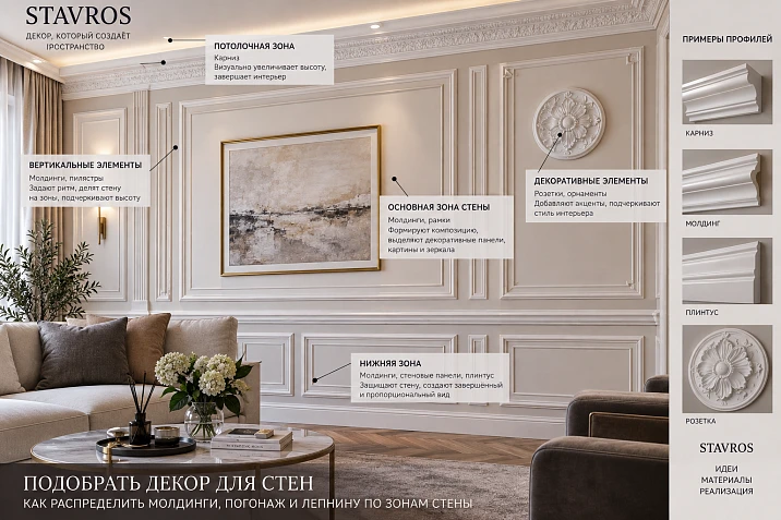
Architectural zoning helps distribute attention. The lower part connects the wall with the floor and furniture, the main field forms the pattern, and the upper part completes the composition. Transitions provide a connection with openings and adjacent surfaces.
The accent zone does not have to occupy a separate horizontal band. It can be located within the main field — for example, around the headboard or above the console.
| Zone | What it does | Possible elements | What limits the solution |
|---|---|---|---|
| Bottom | Connects the wall to the floor | Skirting board, panel, horizontal molding | Furniture, cleaning, contact with objects |
| Main field | Sets the division of the surface | Frames, vertical profiles, trims | Openings, axes, free areas |
| Accent | Highlights the selected center | Panel, overlay, medallion | Furniture size and surrounding field |
| Top | Completes the layout | Frieze, horizontal band, cornice | Ceiling, light fixtures, top of furniture |
| Transitions | Connects or separates areas | Profile ends, frames | Doors, cabinets, corners, niches |
Such a scheme does not require using all the listed items. For one wall, a baseboard and a large frame are enough. For another, a developed upper band is needed, while the main field remains without divisions. The solution is determined by the function of the area.
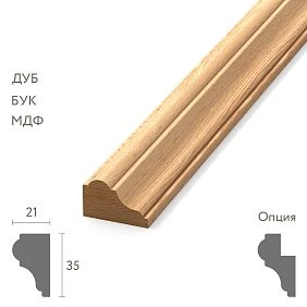
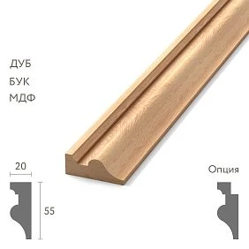
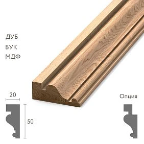
Our factory also produces:
Empty fields should be assigned as consciously as decor
Free space separates the composition from the casing, gives room for a switch, and allows the silhouette of the overlay to be read. When every gap gets its own frame, the wall is fragmented into many equivalent fragments.
On the first elevation, it is convenient to mark three states of the surface: areas with decor, neutral fields, and zones occupied by equipment. Behind a tall cabinet, an additional frame usually does not solve a visible task. Next to an active panel, an empty area, on the contrary, helps keep attention on the center.
The neutral strip is assessed together with neighboring details. A gap that seems sufficient between two thin profiles may look tight next to a wide carved overlay. Therefore, distances are assigned after applying the real outer contour of the items, including protruding leaves, scrolls, and ends. A conventional rectangle instead of ornament can hide such a collision.
Get Consultation
Choosing the axis: wall, free field, or furniture
The wall in our example has three possible centers. The geometric midpoint is at 2400 mm. The free section between the door and the cabinet occupies 3050 mm, its midpoint is 2675 mm. The sofa axis runs at 2700 mm.
For the composition above the sofa, we will choose the latter. A frame 2400 mm wide will occupy the section from 1500 to 3900 mm. Between it and the casing there will be 350 mm, between the frame and the cabinet — 300 mm. The unequal side fields here are explained by alignment to the furniture; there is no need to automatically shift the frame to equalize them.
However, such alignment is stable only if the position of the sofa is coordinated. If rearrangement is planned, it is more reasonable to rely on the architecture of the free section. When selecting decorative elements for the project, it is important to record the chosen basis: “sofa axis” or “middle of the wall section.” Then the next adjustment of the furniture will not go unnoticed for the layout.
Lower and upper zones: checking visible areas
In a conditional example, let us take a frame with a height of 1400 mm: the lower side is at the 1100 mm mark, the upper side at 2500 mm. Above the back of the sofa, 250 mm will remain; under the cornice, 180 mm. These distances show the result of the chosen scheme, but they do not yet confirm its success: an assessment with furniture and under real lighting is needed.
The lower zone behind the sofa can be left smooth. If a horizontal band runs across the room, it is necessary to decide whether it continues behind the furniture for the sake of future rearrangement or ends earlier. This affects both the visible endings and the amount of material.
The upper strip should not automatically be turned into a frieze. An additional ornament 150 mm high will almost fill the available 180 mm, leaving little space around it. Sometimes the cornice alone already provides completeness, and the free strip between it and the frame maintains a clear separation of the two elements.
Walls behind the bed, sofa, and TV
Behind the bed, the headboard axis becomes a strong foundation. At the same time, the composition may cover only the bed or the entire ensemble with nightstands and lamps. These options give different widths of the central field. Wall lights are checked simultaneously with the frames: the fixture must not accidentally end up at the intersection of the profiles.
Behind the sofa, one large panel, several fields, or asymmetry are possible. A corner sofa is especially important to show in the overall view of the room: a frontal elevation does not explain how its long section changes the perception of the center. If paintings are planned, their dimensions are included in the composition in advance.
On the TV wall, the screen, cabinet, cable outlets, and access to equipment are placed first. The frame is checked with the bracket in its working position. Space required by the equipment specifications must remain behind the screen; the relief must not interfere with installation and maintenance. A central overlay is appropriate here only if there is a separate free field where it does not compete with the screen.
Molding is chosen for a specific function
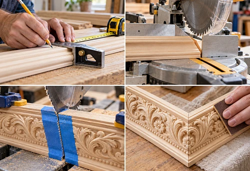
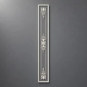
Polyurethane wall moldings can perform different tasks: outlining a frame, separating finishes, continuing a horizontal line, or framing a panel. The function affects the requirements for the profile. For the boundary between two materials, the junction detail is important; for a frame, the width of the line and the character of the corners; for a long band, its passage across the entire wall.
Molding belongs to linear trim products: it is used in extended lengths. Therefore, there is no need to contrast “molding” and “linear trim” as two mandatory purchases. A smooth profile and an ornamental strip differ primarily in their role in the composition.
В in the molding catalog First, a candidate is selected for the main line. On the layout, it is assigned a designation, for example M-01. If one position confidently solves the task, additional profiles may not be introduced. The material and finish are checked in the card of the selected product.
Profile width: from a small wall section to a large field
To assess width, it is more useful to calculate the remaining inner field than to tie the molding size only to ceiling height. Suppose a small wall section is 500 mm wide. After side margins of 80 mm each, the outer size of the frame will be 340 mm.
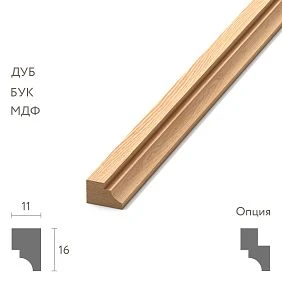
Let's compare two real STAVROS profiles: MLDPU-001 measuring 10 × 6 × 2600 mm и MLDPU-002 measuring 22 × 11 × 2600 mm. In both cases, the material is polyurethane.
| Option | Profile width | Outer frame width | Inner width |
|---|---|---|---|
| MLDPU-001 | 10 мм | 340 мм | 320 мм |
| MLDPU-002 | 22 мм | 340 мм | 296 мм |
The calculation helps to see the difference, but it does not appoint a winner. A narrow tall frame may look accidental even with a thin profile; sometimes it is better to leave the wall section free.
On a large wall, one first compares a single large frame with several independent fields. Increasing the number of modules adds corners, joints, and gaps between frames. The scale of decorative wall moulding is determined by this entire grid, not just by the size of an individual strip.
Depth and light-and-shadow change the perception of the layout
Conventional profiles with cross-sections of 40 × 8 and 40 × 20 mm will occupy the same surface width, but will protrude differently and cast different shadows. These dimensions are given to compare geometry, not as designations of specific products.
Dimension C in the product card should be read according to the product drawing: it describes thickness or the maximum overall dimension in depth, not the depth of each recess in the ornament. The character of the light-and-shadow also depends on fillets, steps, and the direction of light.
The overall installation plane is also checked. A profile 11 mm thick on a panel 8 mm thick will give a nominal projection of 19 mm from the wall, excluding the installation layer. The adjacent architrave is compared specifically with this assembly. If you look only at the thickness of the moulding, you can miss the framing protruding beyond the door decor. Such a difference is especially noticeable in a side view from the entrance.
Second molding and inset frame
An inner contour makes sense when it reinforces the desired division: for example, separating the wallpaper field from the outer framing. The mere presence of a suitable thin profile does not yet explain why the lines on the wall should be doubled.
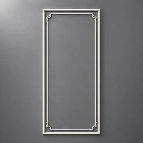
For a conventional frame of 2400 × 1400 mm, let us consider an outer moulding 22 mm wide, a clear gap between profiles of 35 mm, and an inner moulding 10 mm wide. The outer size of the inner frame will be 2286 × 1286 mm. The free field inside it is 2266 × 1266 mm.
Without the additional contour, the field would be 2356 × 1356 mm. The second frame reduces its width by 90 mm and its height also by 90 mm. This must be taken into account when placing a picture or overlay.
The depths of the two profiles are assessed together: the inner contour may be more delicate than the outer one, but the result depends on the light. First the desired effect is chosen, then it is confirmed with samples; there is no automatic compatibility rule based on two dimensions.
Ornamental moulding: where the pattern runs and how it ends
ornamental trim requires checking the repeating pattern. While a smooth line can be assessed by length and cross-section, with an ornament the position of motifs, joints and endings also matter.
On the upper band, determine what will fall on the main axis of the wall: a whole motif, a gap or a joint between planks. Then check both edges. Equal-length remainders do not always produce symmetrical endings if the pattern has a pronounced direction.
The repeat cannot be calculated from the total length of the product: the length of the plank and the repeat spacing of the ornament are different quantities. For the calculation you need an image with dimensions, a drawing or a measured sample.
If the band is interrupted by a door, the left and right parts are considered together. Continuing the rhythm above the opening can tie the wall together, while independent endings can emphasise two separate sections. Both solutions are possible if they are decided before cutting and shown on the elevation.
The central applique occupies the already-checked free field
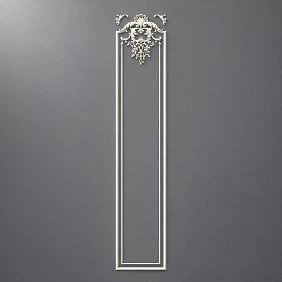
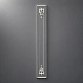
In the usual selection sequence, the frame is approved first, then the Decorative Inserts. This gives piece mouldings clear limits on width, height and position.
You need to compare the full outer contour of the applique with the inner field of the frame. Elongated endings are especially important: in a reduced image they may look almost invisible, although physically they occupy a substantial part of the space. Besides the side clearances, check the distance to furniture, a painting and the top profile.
The central applique does not have to be placed at the geometric centre of the rectangle. Above a console, its position may be determined by a mirror or the upper part of a panel. But the axis and the height mark must be recorded so that installation does not depend on approximate trial fitting.
An exception to the sequence is an already chosen item around which the interior is built: for example, an existing decorative panel. Then its dimensions become the starting point, and the frame is designed to fit them. The solution begins with the most rigid constraint.
Decorative corners: a separate choice for a separate frame
For a rectangular frame, you can consider miter-cutting straight profiles or a ready-made corner element. A decorative corner takes up additional space and changes the character of the frame, so it is useful to test it first on one most significant field.
In the section decoration for moldings there is a selection by specific profiles. For example, MLDPU-002U measuring 172 × 172 × 13 mm is intended for turning a frame with MLDPU-002. Its overall dimension cannot be automatically subtracted from the length of each straight part: the position of the joint is determined by the geometry of the assembly.
It is not necessary to repeat the corner overlays on all frames of a wall. The central panel can receive an elaborate ornament, while the side fields get ordinary joints. This way, the difference in tasks becomes visible. If elements have left and right versions, they are designated separately: turning one part does not always replace a mirrored pair.
A ready-made collection and independent wall assembly
The STAVROS wall section presents the collections “Neoclassic,” “Japandi,” “Versailles,” “Botanical Garden,” and others. A ready-made solution is convenient to consider when coordinated moldings and ornamental details are needed. For a calm geometric wall, one or two separate profiles may be enough.
The collection helps you choose a combination of elements, but its shown composition is still compared with your own openings and furniture. When dimensions change, the lengths and positions of the parts are recalculated. You cannot stretch the entire image together with the ornament: physical products retain their dimensions.
The composition is checked separately. For example, in the product card of the CPU-1-1 set polyurethane and primed MDF are specified: the NPU-399 overlay matches the MLD-003-MG molding. Therefore, the section name does not replace checking the material of each item. When adapting a set, it is clarified which parts are included in the delivery, in what quantity, and what needs to be purchased additionally.
The door and the built-in wardrobe define where the lines end
For a doorway, the scenario is chosen in advance: the frame ends before the casing, the horizontal line continues above the door, or the door leaf is included in the overall panel composition. In the latter case, the finish of the leaf, the gaps, and the opening direction require separate coordination with the door manufacturer.
A small residual area above the casing should not be filled solely to continue the grid. If a full field does not fit there, it is better to revise the height of the line or assign the opening its own framing.
A similar principle applies to the wardrobe. The wall may end before the side panel; the decorative pattern may continue onto the fronts; the wardrobe itself may become the center of the composition. When lines continue onto furniture, the thickness of the fronts, the opening of the doors, and the handles are checked. Molding on a moving part must not interfere with its operation.
The drawing shows the boundary of responsibility: which elements are installed on the wall and which are part of the furniture manufacturing. This helps coordinate the color, elevations, and sequence of work.
Switches, sockets, and adjacent walls
The elevation drawing shows the outer dimension of the electrical mounting frame, not just the center of the back box. Several mechanisms in a common block take up significantly more space than a conventional point. Next to them, an area is left that allows the equipment to be used and its faceplates to be removed.
If the profile crosses a switch, first check whether the layout can be changed. Relocating equipment is discussed with the responsible specialist and reflected in the relevant drawings before finishing. A decorative surround around a socket that accidentally falls within the frame rarely helps maintain a clear composition.
At an interior corner of a room, two walls are assessed at once. A horizontal band can continue at a shared level, while rectangular frames may terminate separately on each side. The visible offsets from the corner matter here: too narrow a strip between two active frames looks accidental. With different modules on adjacent walls, it is useful to maintain a common height line if it supports the room's concept.
Wall moulding for painting: colour does not cancel out relief
Painting moulding in the wall colour reduces colour contrast. However, the protruding profile continues to cast a shadow, and a glossy surface continues to produce highlights. Therefore, the same shade does not guarantee a calm result with a dense grid of frames.
For contrasting moulding, it is especially important to assess the entire wall from a normal distance. A thin dark line may read more actively than a wide profile in the base colour. Before complicating the layout, it is worth comparing options with different numbers of lines using the same finish.
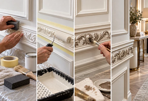
Wall moulding for painting requires coordinating the preparation and coating of specific materials. The moulding, the applique and the wall may have different substrates; the same paint alone does not ensure the same surface. Preparation, primer and application are chosen according to the requirements of the products and the finishing system.
On a test fragment, also check the joints: after painting they may appear differently than on an untreated white piece, especially under light along the wall.
Checking in 3D and against the drawing
Visualisation is needed to assess the entire composition: the frontal view, the view from the entrance, the position of furniture and side light. A close-up of a beautiful profile does not show whether it is successfully distributed across the wall.
In the STAVROS section “Catalogues and drawings” Design materials are provided, including DWG and 3D models. For the selected item code, the file is checked against the product and size variant. If the model appears too small, a different actual product is selected. An arbitrarily enlarged model no longer describes what can be ordered.
After the dimensional check, the dimensions are transferred to the working layout: the outer frame contour, profile width, clear gaps, and axis references. Sections are needed where the mounting plane changes and next to architraves or panels.
The approved drawing set must answer a simple question: can the installer reconstruct the position of all elements without measuring from the picture? If not, the required dimensions have not yet been defined.
Wall sample before final approval
A full room does not need to be assembled for the check. A representative fragment is enough: a section of moulding with a corner, the selected overlay, the base, and the intended finish. For a double frame, the gap between profiles is reproduced; for an ornamental band, the joint and the end.
Samples and catalogs help organize the selection, but the composition of the available sample is clarified separately. A small fragment can show the relief and finish, but it does not always allow the full motif or a large corner element to be assessed.
The sample is viewed under lighting close to the design conditions and from a familiar distance. On the wall, the outer boundaries of the entire composition can additionally be marked with removable tape. It helps assess the size of the field, although it does not replace a three-dimensional sample.
After approval, the item codes, dimensions, shade, gloss level, and accepted surface preparation are recorded. A photograph of the sample is useful as a reminder, and a signed sample as a reference for further work.
Specification and quantity: from layout to order
For the calculation, let us return to the single frame 2400 × 1400 mm from MLDPU-002. We will assume four solid sides with 45° miters, dimensions along the long outer edges. Two lengths of 2400 mm and two of 1400 mm are required: 7.6 linear meters in total.
Dividing 7.6 m by the commercial length of 2.6 m with rounding gives three strips. But the cutting plan requires four: each long side takes a separate strip, and two sides of 1400 mm together do not fit into 2600 mm. In this example, a sufficient difference in lengths remains for trimming and the saw kerf; it is still noted in the cutting plan. The reserve for damage or rework is assigned separately.
| Designation | Product and version | Role | Quantity in the example |
|---|---|---|---|
| M-01 | MLDPU-002, polyurethane, 22 × 11 × 2600 mm | Single frame above the sofa | 4 strips without a separate allowance |
| M-01, reserve | Same execution | Replacement if necessary | Specify after approval |
| Piece decor | Only approved SKUs | Accent or corner finishing | Calculate separately for each item |
The nested contour and decorative corners are considered above as alternatives: they are not included in this calculation. If they are selected, the cutting plan is drawn up anew. Separate rows are needed for left and right overlays; three mirrored pairs mean three left and three right parts, six pieces in total.
A layout, a list of products, and a cutting map are attached to the request. For consultation on selecting moulding, it is also useful to provide photos of the wall and notes on unresolved questions; the terms of interaction are presented in the section for designers and architects.
Before buying wall decor, verify the final product codes, materials, dimensions, quantity, and delivery terms. The order must reproduce the approved wall composition: with the chosen axis, clear line endings, and the free spaces that were included in the project.