Article Contents:
- 1. What a photo can actually determine
- 2. First, establish which part you are looking for
- 3. Which images are needed for confident selection
- 4. How to estimate width using a reference dimension
- 5. Why the whole wall is not suitable as a ruler
- 6. A wide molding is assessed together with the frame
- 7. Depth and cross-section: what can be read from light and shadow
- 8. How to recognize ornamental trim
- 9. How to narrow the catalog down to a few options
- 10. Real STAVROS examples: choosing the article and size together
- 11. How to compare two similar profiles without a scale error
- 12. What to do if there is an arch in the photo
- 13. A complex frame may consist of several products
- 14. How to transfer the selected profile to your wall
- 15. Why DWG and a 3D model are needed after the photo
- 16. What to check on a physical sample
- 17. How to calculate the planks after choosing the article
- 18. What to send to a specialist for selection
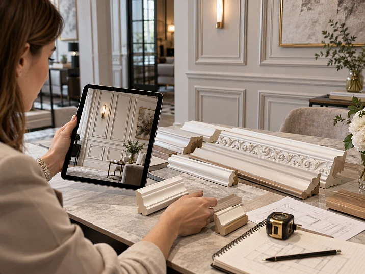
In the photograph, the frame looks thin, but the molding chosen based on its image turns out to be too wide. Or the width matches, but after installation a heavy shadow appears along the wall that was almost absent in the interior you liked. The mistake occurs before the purchase: a flat image is taken as a sufficient description of a three-dimensional detail.
Selecting moldings from a photograph begins with separating two tasks. First, you need to understand which features create the desired effect: a narrow contour, a rounded bead, a stepped profile, a repeating ornament. Then, find a product with verifiable dimensions and transfer it into your own space. Between a beautiful photo and an order, there must be a specific article number, a chosen size, and a calculation of the strips.
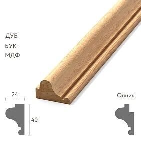
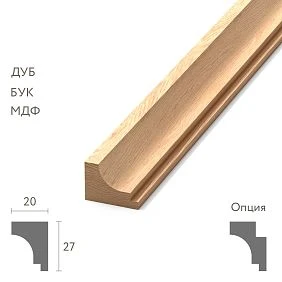
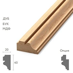
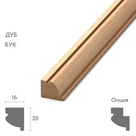
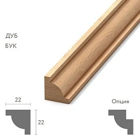
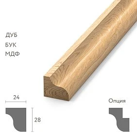
1. What a photograph actually allows you to determine
From a good photograph, you can establish the placement of the decor, the direction of the lines, and the approximate width relative to neighboring objects. The general character of the profile is usually visible too: a calm convex contour differs from a multi-stepped frame even without exact dimensions.
But a photograph does not automatically tell you what the molding is made of, how far it protrudes from the wall, or who manufactured it. Painted wood, gypsum, and polymer decor can look similar. Finding a similar product listing does not yet prove that this exact article number was used in the photo.
| Feature in the photograph | What you can note down for searching | How to confirm before ordering |
|---|---|---|
| Narrow or wide line | Preliminary width range | Reference dimension and drawing |
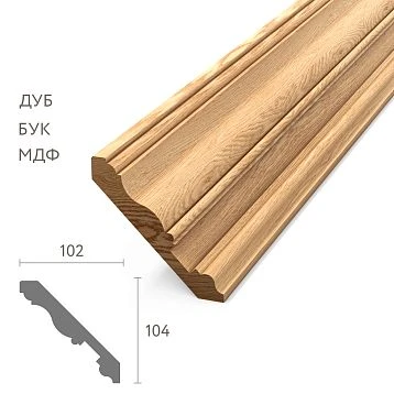
| Convex section, groove, step | Expected cross-section profile | Side view, product cross-section |
| Repeating pattern | Ornament family | Full repeat and corner joint |
| Arc or curved wall | Profile needed for curved section | Object geometry and allowable product bending |
| White painted surface | A similar finish is required | Sample of the selected material |
If the task is to seamlessly extend the surviving stucco, the requirements are stricter than when creating a new interior inspired by a photograph. In the first case, the cross-section must match at the joint; in the second, a profile of a similar character is acceptable.




2. First, determine which part you are looking for
A straight decorative line may turn out to be a molding, casing, baseboard, or part of a cornice. Look at where it runs and what it adjoins. A frame on a flat wall is one task; the transition between wall and ceiling is another. For a cornice, two adjoining surfaces must be considered at once.
Door framing should not automatically be sought among wall frames either. The casing is tied to the structure of the opening, while an adjacent molding may only repeat some lines of its pattern. At the bottom of the wall, check whether a separate baseboard is shown or several profiles assembled into a single composition.
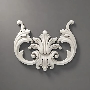
Identify individual pieces separately. The flower above the frame, the corner scroll, and the central overlay are not necessarily cast together with the straight strip. If you search for the entire composition as one complex profile, the needed items are easy to miss.
In the moldings from polyurethane it is more convenient to first choose the purpose of the element. Leave the name of the interior style as an additional reference: "classic" describes too broad a range of forms.
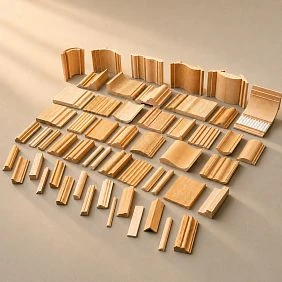
Our factory also produces:
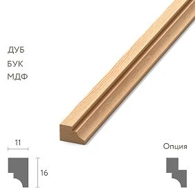
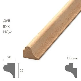
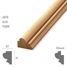
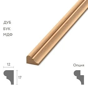
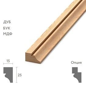
3. Which images are needed for confident selection
Save the original photo in full and make an enlarged fragment separately. The general view shows the molding's place in the composition; the close-up helps examine the transitions of the relief. A cropped corner of a frame without the door, furniture, and adjacent lines gives almost no idea of scale.
If the interior itself is available, photograph the front wall, the profile at an angle, and the joint between the two strips. Add a shot with a ruler next to the component. The ruler must lie in a comparable plane; otherwise its image and the image of the profile will be at different scales.
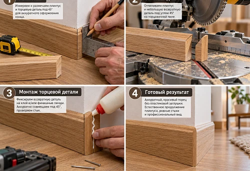
An exposed end face is useful: it shows the cross-section shape directly. On old finishes, take into account layers of paint and repair fillers — they can smooth out the grooves and alter the visible edge.
Clarify the origin of the image. An architectural visualization may contain schematic geometry that is not available for sale. Enlarging an image with automatic inpainting also does not make small details reliable: the program can add lines that were absent from the source file. For identification, use the original, not an enhanced copy.
Get Consultation
4. How to estimate width using a reference dimension
You need an object whose size is genuinely known. A measured section of wall, a tile of established format, or a ruler placed in the shot will work. The width of a door, socket, or skirting board cannot be assigned from memory: visually similar products come in different sizes.
For a preliminary calculation, compare lengths in the image:
Molding width ≈ known dimension × molding width in the photo / length of the known dimension in the photo.
A hypothetical example: a tile side 200 mm long occupies 100 pixels. The visible width of a nearby molding is about 15–18 pixels. At a comparable scale, this gives a range of 30–36 mm. This is a basis for considering several close sizes, not for writing “33 mm” in the order.
Measure the profile itself between its outer edges. The shadow on the wall is not included in this dimension. In a blurry image, the boundary may span several pixels, so it is more sensible to record the result as a range.
The segments being compared should be close to each other, in the same plane, and oriented in the same direction. If these conditions are not met, a simple proportion becomes unreliable. In that case, it is more honest to leave the width unconfirmed and look for additional images.
5. Why the entire wall is not suitable as a ruler
In a photograph taken from the corner of a room, the near part of the wall appears larger than the far part. Therefore, you cannot measure the width of the molding at the edge of the frame using the overall wall width and consider the resulting value accurate.
Even two identical vertical profiles can appear different in width. If one is located near the camera and the other in the background, averaging the results does not eliminate the error — it merely hides the cause of the discrepancy.
Perspective correction helps compare elements of a single flat wall when its geometry is known. However, it does not restore a hidden cross-section and does not automatically correct lens distortions. A detail on a protruding panel is still in a different plane.
For practical selection, it is better to obtain one clear reference dimension next to the profile than ten questionable measurements across the entire frame.
6. A wide molding is assessed together with the frame
A 35 mm wide profile looks different on a large wall panel and on a narrow wall section. In the first case, it may be perceived as a neat border; in the second, it may occupy a noticeable part of the free field. Therefore, the query "wide molding for a polyurethane wall" should be refined with the dimensions of the composition itself.
Let us consider a conventional frame with an outer width of 500 mm. With a profile width of 20 mm, the inner opening will be 460 mm; with a width of 35 mm, it will be 430 mm. The outer contour remains the same, but the free field decreases by 30 mm. This is noticeable if sconces, a painting, or a decorative overlay are planned inside.
In the reference, compare not only the profile and the door. Look at how much free space remains between adjacent frames, furniture, and the door casing. For your own wall, these distances need to be checked again: a successful ratio in the photograph does not guarantee a successful result in a more cramped room.
7. Depth and cross-section: what can be read from light and shadow
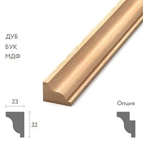
The same width does not mean the same volume. Two conventional profiles 35 mm wide with a 7 mm and an 18 mm projection will be perceived differently from the side and next to the casing. At the same time, the overall thickness of the part is not equal to the depth of an individual groove or the difference in its relief.
In the photograph, look for a sequence of shapes: a flat band, a convex roll, a concave cove, a step. Several parallel light and dark lines may indicate a complex section. A single smooth transition more often helps to identify a simple convex area. Record the observation as an assumption until a side view appears.
You cannot calculate the projection from the length of a shadow without information about the lighting. Low directional light can make a shallow profile appear visually massive; diffuse light can almost hide a pronounced relief. A dark line may also be a painted stripe or a gap between parts.
For the item you have found, compare the width, projection and section pattern. If the front photograph seems suitable, but the drawing shows a different sequence of rolls and hollows, the similarity will depend on the viewing angle. Under side lighting, the difference will be more pronounced.
8. How to recognize ornamental moulding
A smooth moulding keeps its section along its length. In ornamental moulding, leaves, beads, interlace or geometric elements repeat along the strip. Here, another parameter is added to width and projection — the repeat spacing of the pattern, that is, the rapport.
First determine the family of the motif. For a search, it is enough to notice a plant pattern, a chain of beads, a weave or an ionic motif. If only part of a leaf is visible, you should not confidently call it acanthus: a cropped fragment may belong to another ornament.
In the section polyurethane molding compare several consecutive repeats. One similar scroll says little about the rhythm of the whole line. Two items may share individual motifs but differ in the distances between them and the density of filling.
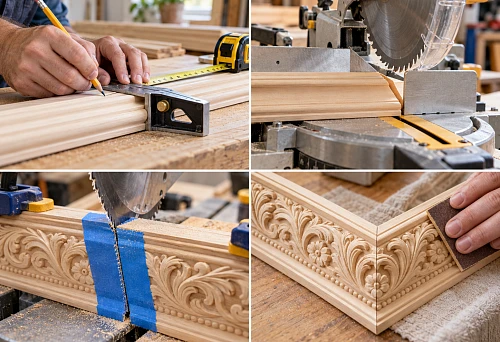
Look at how the pattern passes through the corner and ends near the opening. A trim that is acceptable on a straight section may leave half of a noticeable element in the corner. For a directional ornament, additionally check the position of the top and bottom, as well as the alignment of the left and right sides of the frame.
9. How to narrow the catalog down to a few options
Before viewing the product cards, write a short description: "wall frame, smooth profile, pronounced bead, approximate width 30–36 mm, projection not yet known." Such a note is more useful than the wording "molding as in the photo" and does not present an assumption as a measurement.
Open Moldings made of polyurethane and first select suitable shapes. Then compare the size options. Check the material in each product card: visual similarity and the product's position in the selection do not replace the specifications of the specific item.
For a repeating pattern, separately review Polyurethane molding. Do not mix a straight strip, a ready-made corner and an overlay in one list: they occupy different lines in the future order.
Keep three to five candidates, and for each record the reason for choosing it and any unresolved question. For example: "suitable in width, need to check the projection near the casing." This will allow you to eliminate options based on a specific mismatch.
10. Real STAVROS examples: item code and size are chosen together
In the product cards for the moldings listed below, dimensions are indicated as A × C × L: profile width, its projection and strip length. Always verify the meaning of each letter against the drawing of the selected item.
| Product | A, mm | C, mm | L, mm | What to compare with the photo |
|---|---|---|---|---|
| MLDPU-027, smaller size | 14 | 9 | 2600 | A narrow smooth convex line |
| MLDPU-027, larger size | 20 | 12 | 2600 | The same overall character at a different scale |
| MLDPU-003 | 35 | 12 | 2600 | Wider multi-level profile |
У MLDPU-027 both of the specified sizes are available. Therefore, an entry of "order MLDPU-027" is not enough: the selected profile must be retained in the specification. Substituting 14 × 9 with 20 × 12 changes both the width and the projection at the same time.
MLDPU-003 has a profile of 35 × 12 mm. Its projection matches the larger MLDPU-027 variant, but the width and the construction of the relief are different. This is a clear case where one matching dimension is not enough.
The table shows how to compare real products. It does not mean that any of them suits a particular reference: to draw such a conclusion, you need to see the original photograph and the dimensions of the object.
11. How to compare two similar profiles without a scale error
Images in product cards may occupy the same space on the screen even though the parts themselves differ by a factor of two. That is why comparing two photographs of equal height is often misleading.
Place the profiles of the candidates side by side at a single scale. Then show each profile on the same frame, keeping the wall dimensions and camera position unchanged. If you change the frame width, color, and lighting at the same time, it becomes difficult to determine the cause of the difference.
| Check | What to keep the same | What to look for |
|---|---|---|
| Section geometry | Image scale | Width, projection, relief transitions |
| View of the entire frame | External dimensions and observation point | Free inner field, line density |
| Chiaroscuro | Light, finish and profile position | Readability of grooves and shadow edge |
| Junction | Dimensions of the adjacent architrave or panel | Edge alignment, plane offset |
If the doubt concerns only the width, first compare the outlines on the unfolded view. If the volume is in question, flat lines are no longer enough — a cross-section or a sample will be required. Thus each subsequent check answers a specific question.
12. What to do if there is an arch in the photo
A rounded frame on a flat wall and a horizontal line around a curved wall require different bend directions. A photograph can hide this difference, especially when shot almost head-on.
Before looking for a flexible polyurethane molding, determine the shape of the surface, the bend direction and the radius. For an oval or a complex arc, a single radius is not enough: a contour drawing will be needed. Separately mark where the rounded section transitions into a straight one.
A regular straight profile cannot be considered suitable for an arch just because its material is called polyurethane. The availability of a flexible version, the permissible radius for the required direction and the installation method must be verified with the manufacturer for the specific model. These properties do not follow from external similarity.
If a suitable version is not confirmed, leave the curved section unresolved. It is too early to purchase the entire batch of straight profile on the assumption that it will be "bent on site." First, the product for the arc and its connection to the other lines must be agreed upon.
13. A complex frame may consist of several products
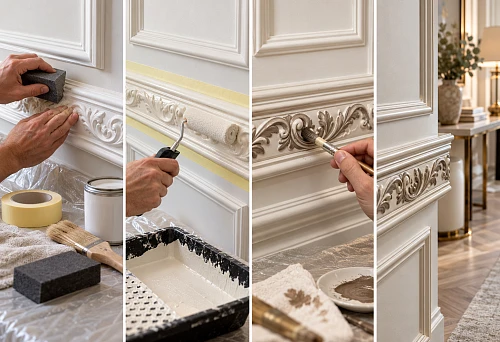
Examine the places where the straight profile turns into a scroll or a floral pattern. If the complication appears only in the corners or in the center, you are probably looking at a combination of linear molding and separate decorative elements.
In the section decoration for moldings look for the required role of the part: corner, central overlay, line termination. Verify compatibility by dimensions and the joint with the specific profile. The proximity of products in the catalog does not by itself confirm that their connecting sections match.
The left and right elements may differ in the direction of the ornament. Rotating one part does not always replace a mirrored pair: the position of the top and bottom changes at the same time. In the bill of materials, such items are recorded separately.
A ready-made corner can also change the length of straight segments. Before calculating, determine where the molding ends: it abuts the part, tucks under it, or connects in another specified way. If in the photo the joint is hidden by paint, its construction must be clarified from the drawing rather than guessed.
14. How to transfer the selected profile onto your wall
Start with a layout of the actual room: mark the openings, baseboard, furniture and equipment. Indicate the actual dimensions after finishing, or clearly state which thicknesses still need to be accounted for. Only then place the frames.
From the reference you can take the principle: a large central field and two narrow side ones, a common top line, or alignment to the door. The number of frames, their width and the intervals are determined anew. On a short wall, preserving all the divisions of a large hall can make the composition cramped.
Decide in advance what sets the frame size: the outer edge of the molding, the inner edge, or the centerline. Otherwise, when replacing the profile with a wider one, the installer and the designer may interpret the same dimension chain differently.
Check the opening of doors and furniture, the position of switches, and the distance to the door casing. For a frame on a panel, take into account the full depth of the assembly: the protrusion of the molding is measured from its installation surface, and the panel already protrudes relative to the wall. Such a check sometimes rules out a visually suitable item even before ordering a sample.
15. Why DWG and a 3D model are needed after the photo
The drawing is responsible for the geometry, the 3D model for checking the selected part in the project space. In the section STAVROS catalogs and drawings materials on polyurethane decor are presented, including DWG and three-dimensional models. Verify the file against the item code and the dimensional version in the order.
After insertion, measure a known dimension of the model. A unit error or accidental scaling can turn a real part into a fictitious one. Do not stretch the profile across to fit it to the photo: after such an operation, the image will no longer correspond to the product being purchased.
On the drawing, check the mounting plane, the maximum protrusion and the local edge height near the junction. On a complex profile, the edge may be considerably lower than the central bead. For joining with the architrave, this matters more than a single overall thickness figure.
In the 3D scene, assess the view from normal room viewpoints and under the specified lighting. A beautiful close-up does not replace the overall view from the entrance. If the required file is missing, request it or agree on dimensions using the technical image; do not pass off a similar model of a different item code as the exact one.
16. What to check on a physical sample
A sample is especially useful with side lighting, deep relief and junctions with joinery products. It resolves specific doubts: how heavy the line looks, whether the groove reads after painting, whether the edges of adjacent parts match.
Clarify whether you can obtain a sample of the exact selected item code and profile. In product samples section different formats are presented, so the composition and purpose of a specific set must be checked. A general material sample does not replace a sample of the required profile.
Attach the part to the intended installation location and step back to a normal viewing distance. To assess the entire frame, add markings of its outer and inner contours. A short fragment lets you examine the relief, but it does not show how several long lines will divide the wall.
If color or sheen remains the deciding factor, carry out an agreed paint trial on the actual profile. A flat paint card does not show how the coating will behave on grooves and raised areas. Sign off the approved sample: item code, size, finish, date. Then, when assembling the batch, there will be something to check against.
17. How to calculate the strips after choosing the item code
First, compile a list of individual segments, then distribute them across the commercial strips. Dividing the total linear meters by the product length gives only a lower estimate: it does not take into account whether the required parts fit into the offcuts.
Conditional example: four rectangular frames with an outer size of 900 × 1900 mm are required, made from a smooth profile with a length of 2600 mm. The corners are cut at 45 degrees; the lengths below are specified along the long points on the outer edge. Each segment must be a single piece.
| Frame parts | Length of one segment, mm | Quantity | Preliminary distribution |
|---|---|---|---|
| Vertical sides | 1900 | 8 | One segment per strip: 8 strips |
| Horizontal sides | 900 | 8 | Two segments per strip: 4 strips |
| Total | 22,400 mm of finished segments | 16 | 12 strips with a separate reserve |
Based on the total linear length, it would be 22.4 / 2.6 — rounded up, nine strips. But a 900 mm segment cannot be added to a 1900 mm segment: together they take up 2800 mm even before machining is taken into account. The remainder after a vertical side is not suitable for a single-piece horizontal side. Therefore, the chosen scheme requires twelve strips.
This is a calculation example, not a ready-made order for any frame. The installer checks the cuts, end trimming and the actual geometry of the corners. For ornamental moulding, pattern matching is also taken into account. The reserve is set after this check, separately from the unavoidable offcuts.
Once the cutting plan is ready, you can Buy polyurethane wall moldings using an exact specification. It lists the article number, cross-section, commercial length, number of strips and additional parts. The cost is compared for the entire set, including agreed related materials and delivery, based on the current offer.
18. What to send a specialist for selection
Prepare an overall photo, a close-up fragment and the known dimensions. Separately attach an elevation drawing of your wall with the openings, ceiling height and furniture. Label the dimensions of the other interior and the dimensions of your own space separately.
State what needs to be preserved: the exact cross-section to continue an existing line, a similar pattern, or the overall lightness of the frame. Specify the article numbers you have already found, the estimated volume, the delivery city and any deadline constraints. If an arch is needed, add its geometry.
Through the section for designers and architects you can reach out with your project materials. In your request, it is useful to ask for several options with links, dimensions and an explanation of the differences, and to clarify the availability of drawings and samples. This is a concrete result that can be compared with the project.
Selecting mouldings from a photo is complete when the chosen product has been checked on your wall, all size options are unambiguously recorded, and the linear footage has been converted into the number of strips. Keep the photo next to the specification: it explains the intent. The approved dimensions and article numbers are the basis for purchase and installation.