








































































Article Contents:
- First, describe the wall and adjacent materials
- The mounting plane determines how the profile sits
- Molding on a painted wall: check the paint itself
- Molding on paintable wallpaper: two different processes
- Junction with decorative plaster
- Three molding layouts near a wall panel
- Molding next to a door casing
- How to coordinate molding with a baseboard
- A built-in wardrobe and furniture facade change the requirements
- Width A and depth C answer different questions
- Compatibility table for a single wall
- How to compare real cross-section options
- Example: why depth cannot be compared without a common baseline
- Why a single visualization is not enough
- The sample is checked together with the adjacent finish
- The coating is part of compatibility
- Smooth profile or ornamental moulding
- A radius requires a custom execution
- The shortlist should show the reason for the choice
- What to record after approval
- Calculate cutting after checking the joints
- How to move from selection to purchase
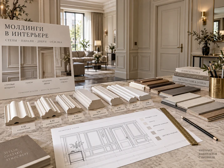
A molding may fit between the door and the wall panel in the elevation drawing, but protrude in front of the door casing after installation. The reason is often hidden in the layers of finish: the panel is mounted on a substructure, the door casing has its own seating, and the decorative profile is glued to a different plane. Comparing only the product dimensions in the catalog is not enough.
Selecting moldings for an interior begins with answering a specific question: where will the mounting back be, and what will the edges of the profile meet? Once this is determined, you can choose the pattern, check a sample, and proceed to order. This order is especially useful where paint, panels, a door portal, and built-in furniture meet on one wall.
First, describe the wall and adjacent materials
To choose a profile, you need a short record of the wall construction. For example: drywall, filler, paint; next to it — a panel on a separate base, a door casing, and a floor skirting board. If the finish is already completed, the record is supplemented with actual measurements. The design thickness of the cladding and its position on site may differ.
On the elevation drawing, mark the areas where the surface under the molding changes. One continuous line can run across a painted wall, approach a panel, and end near a cabinet. Each area has its own conditions for fastening and adjoining, even if the decorative pattern remains the same.
Before opening catalog of polyurethane moldings, determine the available strip on the wall, the allowable protrusion, and the end points. These constraints will help immediately rule out unsuitable sizes.




The mounting plane determines how the profile seats
The mounting plane is the surface that the back of the molding faces. This can be a prepared wall, the face of a panel, or a furniture front. The position of this surface must be shown in section, especially if there is a step between materials nearby.
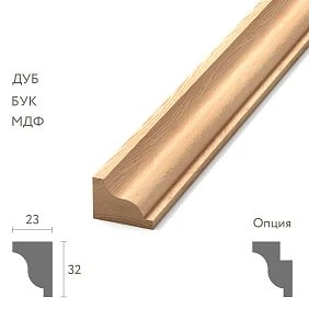
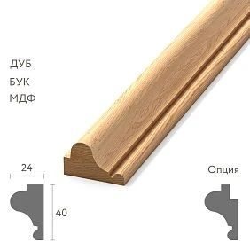
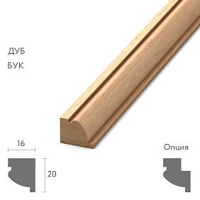
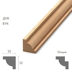
For a decorative profile, the face width and the working adhesive area do not necessarily coincide. The back may have rebates and separate contact zones. From a frontal photo, it is impossible to determine how they will land on the substrate. A cross-section of the product, manufacturer's data, and, if information is insufficient, a sample are needed.
If a flat back overhangs a level difference, a wide profile by itself does not solve the problem. A different profile or a specially designed substrate will be required. Filling the void with an arbitrarily thick layer of adhesive cannot be considered a finished technical solution: the permissible joint thickness is determined by the specific fastening system.
Our factory also produces:
Molding on a painted wall: check the paint itself
Moldings for a painted wall are selected taking into account the condition of the coating. A smooth surface may have a weak bond with the filler, contamination, or peeling areas. Then the glued part is held on an unreliable intermediate layer. Before choosing the mounting compound, the contractor assesses the substrate and provides for the necessary preparation.
The paint itself also matters: its type, degree of drying, porosity, and compatibility with the adhesive. The label "universal" on the packaging does not replace checking the combination of materials. In STAVROS recommendations on finishing and installation fastening options differ depending on the decor material and the condition of the surface. For the selected product, the recommendations are compared with the documentation of the compound used.
If the stucco on a wall to be painted will be painted together with the wall, the treatment of joints and brush access to the edges are planned in advance. A deep recess near an adjacent panel can complicate finishing even for a small molding.
Get Consultation
Molding on paintable wallpaper: two different processes
The first scenario is to install the profile on a prepared base, then finish the adjacent areas with wallpaper. Here the cutting line for the panels, the painting sequence, and the visible edge are set in advance. A narrow strip of wallpaper that would have to be tucked into an awkward gap may be an argument in favor of a different molding width.
The second scenario is wallpaper first, then molding and overall painting. It is permissible only with confirmed compatibility of the specific wallpaper, its adhesion, the profile, and the installation compound. The wallpaper becomes part of the fastening joint; the strength of one adhesive does not confirm the reliability of the entire system.
Manufacturers' requirements vary. For example, Orac recommends removing wallpaper under its products. This requirement applies to Orac products and its installation system and does not replace recommendations for another brand.
Therefore, the wording "moldings on wallpaper" is not sufficient for a working solution. The project specifies what exactly is under the back edge, how the edge of the panel is finished, and who approved the chosen sequence of work.
Junction with decorative plaster
With textured plaster, not only the nominal thickness matters, but also the relief near the future line. A profile placed against the protrusions may leave noticeable gaps in the recesses. If the base beneath it is to be leveled, the boundary of the prepared area must be set before applying the decorative coating.
It is decided separately which material forms the clean edge. You can first install the profile and finish toward it, or plan installation after the surface is completed—with a suitable base and an approved technology. In both cases, it is necessary to check the protection of the adjacent coating during the work.
Next to an active texture, a smooth wall molding is often easier to coordinate visually. But a calm pattern does not compensate for an uneven fit: the technical and decorative tasks are checked separately.
Three molding schemes near a wall panel
Over the panel. The mounting back is entirely located on its front side. Then the outer position of the molding is made up of the position of the panel and the profile's own depth, taking into account the mounting assembly. Check whether the panel's coating allows such bonding and whether there is enough area for contact.
Next to the panel. The molding rests on the wall, while the cladding occupies the adjacent zone. In the section, it is visible what protrudes forward, whether the panel's end face remains open, and what character the gap between the parts has. These surfaces may intentionally be at different levels.
Through the transition. The profile covers the boundary of two planes. This requires suitable back geometry and a well-thought-out support. An ordinary flat strip does not become a transition element just because it covers a step in the front view.
When choosing a scheme, take into account the possible mutual movement of materials. The expansion joint provided by the cladding system cannot simply be hidden with a rigidly glued molding without a corresponding assembly. Otherwise, the decorative line connects areas that need independence.
Molding next to a door casing
Near the door, compare the width of both parts, the distance between them, and the position of the front surfaces. The section where the molding ends is especially important. The maximum depth of the casing may occur at the central bead, while at the side edge its cross-section is substantially lower.
Therefore, the condition “the molding depth is less than the casing depth” does not yet prove a neat junction. In the section, it is necessary to compare the local dimensions precisely at the point of contact. If the end of the molding turns out to be higher than the edge of the casing, it will have to be finished differently, moved back, or the profile changed.
For moldings near doors, also check the opening of the leaf, the movement of the handle, and access to serviceable elements. The free area shown in the elevation is not always free when the door is open. The choice of molding for door trim must take these provisions into account before approving the article number.
How to coordinate molding with baseboard
The baseboard, wall frame, and cornice serve different compositional purposes. They do not need to have the same cross-section, but a random protrusion of a thin frame in front of the top edge of the baseboard can make the lower junction look rough. Real profiles and their position after installation are compared.
A vertical molding can be terminated above the baseboard, brought up to it, finished with a separate element, or included in a closed frame. The option is chosen together with the width and depth of the piece. There is no universal offset: it depends on the geometry, the wall pattern, and the ability to neatly finish the end.
If a gap is provided, the drawing shows between which points it is measured. The distance to the top contour of the baseboard and the distance to its most protruding part can describe different conditions. For the contractor, a completed junction with dimensions is important, not just the position of the molding centerline.
A built-in wardrobe and furniture facade change the requirements
For the wardrobe, it is necessary to determine where the wall profile ends: in front of the side panel, behind the carcass, or on a separate section of the facade. If the molding runs behind the furniture, its protrusion is taken into account in the wardrobe fit. Otherwise, the carcass will not occupy the intended position relative to the wall.
The continuation of the line on the door is made as a separate piece. A fixed wall and an opening facade cannot be connected with a single rigid profile. Gaps required by the furniture construction are maintained between the parts, and they are checked with the door closed and open.
For molding on a facade, the surface material, door thickness, hinge operation, and the position of the handle and adjacent facade are additionally important. The compatibility of the wall junction is not automatically transferred here. Even a light decorative profile can interfere with opening due to its projection. These constraints are communicated to the furniture maker before the parts are manufactured, and the fastening method is coordinated with the facade finish.
Width A and depth C answer different questions
Width A shows how much space the front part of the profile occupies across the line. It is checked relative to sockets, switches, architraves, furniture, and the inner field of the frame. If the composition is set along axes, replacing a narrow molding with a wide one will reduce the free field and change the distances to neighboring objects.
Depth C characterizes the cross-section dimension from its mounting base in accordance with the product drawing. To check the projection in the room, the position of the mounting plane itself is added to it. Profiles of the same depth installed on a wall and on a panel will end up at different levels.
Neither A nor C fully describes the cross-section. Contact with the casing requires the edge shape, gluing requires the back, and evaluating the shadow requires the entire relief and lighting. Length L will be needed when cutting, once geometric compatibility has already been verified.
Compatibility table for one wall
To select moldings for a project, it is convenient to gather the conditions into a single table. It links materials with checks and shows what data still needs to be obtained. The entry "suitable" appears only after a specific combination has been verified.
| Section | What is being compared | What is recorded in the project |
|---|---|---|
| Painted wall | Coating condition, back, mounting compound | Surface preparation and fastening system |
| Wallpaper for painting | Layers under the profile and the order of work | Canvas edge and finishing sequence |
| Wall panel | Panel position, backrest support, local section | Installation scheme and end treatment |
| Door casing | Local depth at the junction, width and gap | Dimensional section of the end |
| Baseboard | Upper contour and protruding parts | Offset, junction or termination |
| Built-in furniture | Fixed and movable parts | Part separation and opening gaps |
| Radiused section | Radius, bend direction, profile design | Confirmed model and installation method |
For a long wall, you can add section designations and node numbers. Then the same molding does not receive general approval for all surfaces just because it passed inspection on the painted part.
Suppose a horizontal line runs along a painted wall and must continue onto a veneered panel. On the wall, the backrest gets one base, on the panel another, and the front surface of the panel is offset forward. Two application rows of the same profile appear in the table. For the first, paint preparation is checked, for the second, the veneer coating, and at the boundary the transition between levels is decided separately.
If continuous continuation cannot be achieved with the selected section, there are several design solutions: end the line before the panel, change the position of its base, or select a separate transition piece. The choice depends on the design intent and whether modifying the structure is acceptable. The problem cannot be closed with an "approved" mark for the article alone: the method of its installation on each section must also be approved.
How to compare real section options
At STAVROS MLDPU-027 is available in sizes 14 × 9 × 2600 and 20 × 12 × 2600 mm. These are two options under one article number. For comparison, let's also take MLDPU-003 size 35 × 12 × 2600 mm. All three considered designs are made of polyurethane.
Suppose the project allocates a strip no wider than 22 mm for the profile, and the permissible depth relative to its mounting base is 12 mm. This is a conditional example, not a standard.
| Option | A, mm | C, mm | L, mm | Preliminary result |
|---|---|---|---|---|
| MLDPU-027, small section | 14 | 9 | 2600 | Passes both specified constraints |
| MLDPU-027, large section | 20 | 12 | 2600 | Passes both specified constraints |
| MLDPU-003 | 35 | 12 | 2600 | Does not fit within the designated strip |
This is only a geometric selection. The table does not confirm adhesive suitability, backrest support, or the quality of the joint. The two remaining options need to be transferred to the wall section and verified on a sample.
A boundary match also requires attention: a dimension of 12 mm against a limit of 12 mm leaves no allowance provided for by this condition. If the adjacent part is already installed, the permissible protrusion is clarified by measurement. Dimensional deviations of the product and installation are taken into account based on confirmed data, not assigned arbitrarily.
Example: why depth cannot be compared without a common datum
Let us imagine a design detail where the front face of the panel is 16 mm from the selected common datum, and the back face of the installed molding is 3 mm from it. These 3 mm indicate the final position of the back face, taking into account substrate preparation and the installation detail. This is not a recommended adhesive layer thickness; adding installation allowances in this example is not required.
For the option with a depth of 9 mm, the most protruding point will be at 3 + 9 = 12 mm. It will be 4 mm behind the panel plane. With a depth of 12 mm, it will be 3 + 12 = 15 mm, that is, 1 mm behind the panel.
But neither result yet means that the profile will neatly cover its end face. The calculation determines the position of the maximum protrusion. For the transition between materials, it is necessary to check the edge shape, the contact zones of the back face, and the treatment of the exposed end face. This is exactly where the catalog dimension is supplemented by the detail drawing.
Why one visualization is not enough
In a perspective image, a small offset is easily lost in the light, material, or smoothing. A dimensional section shows it regardless of how expressive the picture is. It should show the base, finish layers, profile, and the adjacent part with references to a single datum.
Section 3D and DWG STAVROS helps find materials for design. When using the file, check which article number, size variant, and units of measurement it corresponds to. The presence of a model by itself does not confirm that it fits correctly in the project.
A complex junction is useful to show at 1:1 scale with a control dimension to verify the print scale. For moldings for designers and architects, such a section links the selected product to a specific wall construction and the instructions to the contractor.
The sample is checked together with the adjacent finish
After selecting two or three options, assemble a small fragment of the assembly: a wall sample with the chosen paint, a panel on the specified substrate, a section of casing, and molding. Individual materials laid out on a table allow you to compare color but do not show their relative position after installation.
In the mockup, check the fit, the visible end, access for painting, and the shadow under typical lighting. If a wall light fixture is nearby, examine the sample under a similar light direction. Then note what exactly is approved: geometry, color, gloss, or the entire assembly.
It is better to record the result of the check specifically: “the edge of the panel remains open,” “the brush does not pass between the profile and the casing,” “the door touches the convex part.” Such a note suggests what to change: the cross-section, the position, or the finishing sequence. The wording “I did not like the sample” does not help prepare the next option and may lead to reordering almost the same part.
Through the section Samples and catalogs you can clarify the available ways to get acquainted with the products. The possibility of obtaining a fragment of a specific profile and the required cross-section should be agreed separately. A sample made of a different material or size does not confirm the selected fit.
Coating is part of compatibility
The same color designation does not guarantee the same appearance of the wall and molding. Perception is influenced by surface preparation, texture, gloss level, and relief. Therefore, a molding color-matched to the wall is checked after applying the specified coating system, not on an unpainted blank next to a paper fan deck.
For the substrate, primer, and topcoat, mutual compatibility and application order are checked. An already primed profile may require different preparation than an unpainted part. These differences are clarified according to the selected product and the finishing materials documentation.
Section Polyurethane moldings helps assemble the decorative elements of the project, but the material and delivery condition of each item are checked separately. The color sample is approved together with the adjacent paint or panel: a change in gloss can make a calm line much more noticeable.
Smooth profile or ornamental trim
A smooth molding works well next to expressive plaster, wood grain, and complex furniture fronts. It marks the boundary without additional ornament. At the same time, its convexity, edges, and shadow remain part of the composition; the absence of a pattern does not make any profile invisible.
If the profile is to become a standalone accent, consider Polyurethane trim. For products with a repeating pattern, the repeat length, joint position, and termination near a panel or casing are important. A shortened fragment of the ornament in a prominent place sometimes requires changing the entire layout.
Choosing ornamental trim, align the pattern on straight sections and corners. If used Decor for Molding, its compatibility with the selected profile is checked separately. A match in style does not confirm a match in profiles.
The radius requires a separate specification
On a curved surface, the base radius, bend direction, and suitability of a specific profile are checked. The word "flexible" without this information says nothing about the part's suitability for the assembly. Acceptable parameters apply to a specific model and specification.
The limitations of a flexible product from another manufacturer cannot be transferred to a visually similar molding. Also, a flexible version should not automatically become a way to work around an unprepared wavy wall: the intended base geometry must first be determined.
If the availability of the required specification is not confirmed, the radius section is left as a separate unresolved item in the project. Ordering the entire linear run as a single agreed set at this stage is premature.
The shortlist should show the reason for the choice
A useful selection of architectural decor contains several candidates with clear rationales: one fits near a narrow casing, another aligns better with a panel, and a third allows the required termination. This helps the client discuss the consequences of the choice, and the contractor verify the solution.
If an additional Wall Decor, its projection and installation conditions are added to the same checks. The center overlay must not block access to an outlet or land on an unsuitable surface just for the sake of symmetry.
The final list includes options for which clear questions remain that can be resolved by a sample or by clarifying the data. A clearly unsuitable profile is not kept as a backup just because of an attractive photo.
What to record after approval
The specification retains the manufacturer, article number, selected size A × C × L, material, finish, and a link to the product page. The application areas and installation unit numbers are indicated alongside. For a model with multiple sizes, one article number is not enough: the selected section must be repeated in all documents.
The sample approval status and the date of issue of the design solution are recorded separately. The approved profile is transferred to the developments, sections, and visualization. The contractor and the procurement specialist must work with the same version, otherwise a replacement in the image may not make it into the order.
If the panel, architrave, or trim thickness changes later, compatibility is checked again. The molding article number may remain the same, but its mounting base and end piece will already require adjustment.
Calculate the cutting plan after checking the units
A preliminary linear footage is useful for estimating the project, but the final number of strips is determined by the approved sections, end pieces, and commercial length. Replacing the profile can change the frame dimensions, part lengths, and the possibility of using offcuts.
The cutting plan includes straight sections, corners, specified joints, and ornament features. The need for a reserve is justified by the cutting plan and the risks of specific work. The same percentage for all rooms does not take into account whether the longest part can be restored from the remaining offcuts.
The order includes the number of whole strips of each size. Linear meters help verify the volume but do not replace the piece-by-piece list: the same total length may require a different number of items with a different breakdown.
How to move from selection to purchase
Before buying polyurethane wall moldings, the procurement specialist checks the selected option on the product page against the approved specification. They verify the article number, dimensions, material, surface condition, and number of strips. The current price, availability, completeness, and delivery terms are confirmed for the specific order.
If consultation on selecting stucco is needed, it is more useful to send a dimensional wall section and a list of adjacent materials than just a photo of the desired interior. The request should include the selected profiles, a finish sample, and unresolved questions about the back or the junction. Information about working with specialists can be found in the section for designers and architects.
After receiving the product, it is checked against the order before cutting and painting. The marking, dimensions, material, and completeness are verified, and the profile is compared with the approved sample. If a discrepancy is found, it is clarified with the supplier before work begins. This is especially important for an item where different cross-sections are offered under the same product code.
To order interior moldings, provide the supplier with an exact specification, and the contractor with the corresponding sections, elevations, and finishing solution. Keep the approved sample until installation is complete: it will allow you to verify that the purchase and the finished wall match the approved solution.