Article Contents:
- A photograph helps narrow down the options; a sample verifies the decision
- Choose candidates with clear differences for comparison
- The length of the sample depends on what needs to be checked
- Each fragment is labeled immediately and checked against the drawing
- The same width and different depth provide a separate test
- Width is assessed using the free field of the frame
- Comparison requires a single test surface
- Side lighting reveals the cross-section but requires context
- The sample is viewed from a distance and in the design orientation
- A casing, baseboard, and panel are needed next to the sample
- A test 45° corner verifies use in a frame
- A longitudinal joint and a decorative corner require their own tests
- Ornamental trim requires a full motif and repeat
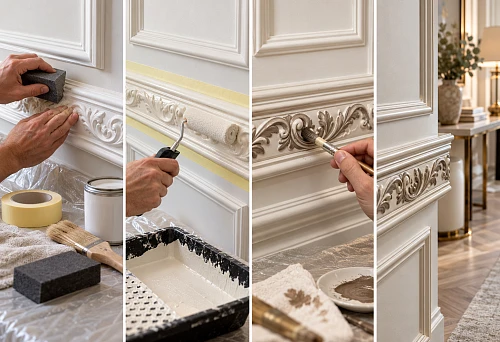
- Test painting is carried out according to the design system
- Painting in the wall color does not eliminate the dimensional line
- A wall fragment links the sample to the overall pattern
- The comparison is recorded according to criteria related to the project
- The approved sample receives a passport and a place on the display stand
- How to order molding samples for a specific check
- After selecting a sample, the link to the purchase is retained
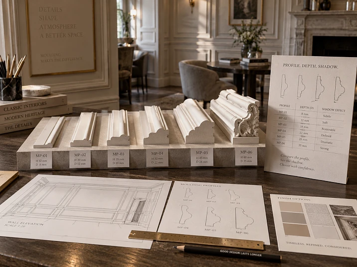
Two moldings with the same thickness of 12 mm can produce different light and shadow. One has a surface that forms a smooth rounded ridge, while the other has several steps and recesses. A frontal photograph smooths out the differences, while light positioned from the side makes them noticeable. Therefore, matching dimensions do not yet mean that the profiles will perform the same way on the wall.
Molding samples are useful for designers precisely at the stage of choosing between specific products. It is necessary to compare several suitable options under the same conditions, check the cross-section, the angle of the frame, and the painted surface. As a result, a specific item code and finish are approved, which then go into the drawings and the order. STAVROS section “Samples, catalogs, display stands” helps select materials for such a preliminary introduction to the products.
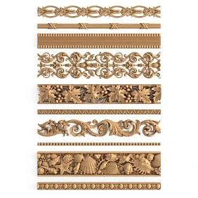
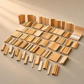
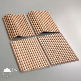
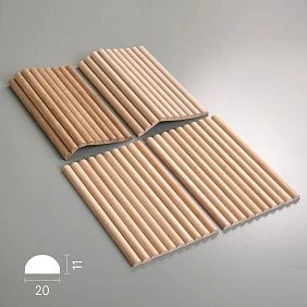
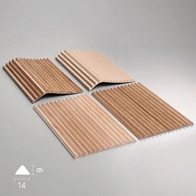
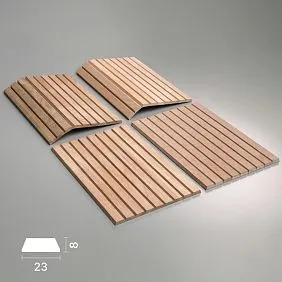
A photograph helps shortlist options, a sample helps verify the decision
The catalog allows you to evaluate the overall pattern of the molding, find the dimensions, and compare it with the interior composition. From the drawing, you can rule out in advance a profile that does not fit next to the architrave or leaves too small an inner field for the frame.
A physical fragment shows how this geometry is perceived in three dimensions. The width of the visible surface, the character of the edge, the depth of the projection, and the transition between illuminated areas and shadow become clearer. After test painting, you can also evaluate the coating and the appearance of the joint.
At the same time, the possibilities of a sample are limited. A short segment does not confirm the straightness of the entire commercial strip, does not show the completed frame, and does not replace checking the installation conditions. It has its own task: to answer specific questions before approving the product.
It is useful to decide in advance what is checked against the product card, what against the drawing, and what in person. Then stucco samples do not turn into a collection of beautiful fragments with no connection to the design solution.




Candidates with clear differences are taken for comparison
It is not necessary to request every profile you like. First, the permissible dimensions, the character of the line, and the constraints of adjacent elements are determined. After reviewing the catalog and drawings, two or three candidates are often enough for a physical comparison.
For example, the following real STAVROS moldings can be compared. All three items are made of polyurethane; the purpose of the check in the table is suggested for work on the project.
| Candidate | Design, mm | What makes sense to compare in person |
|---|---|---|
| MLDPU-027 | 20 × 12 × 2600 | A smooth convex line and how it is perceived on the wall |
| MLDPU-002 | 22 × 11 × 2600 | A multi-level profile with a similar width |
| MLDPU-003 | 35 × 12 × 2600 | A wider line with the same maximum thickness as the first candidate |
This is not a ready-made recommendation for any room. Such a set allows you to check two different tasks: whether a complex relief is needed at a similar width and whether the width of the contour itself needs to be increased.
If the question concerns only thickness, they try to find options with the closest possible remaining characteristics. When width, pattern, and color change simultaneously, the entire visual effect cannot be attributed to a single dimension C.
Our factory also produces:
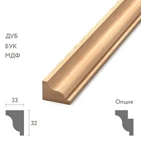
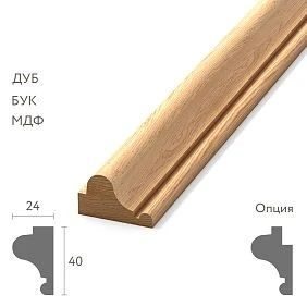
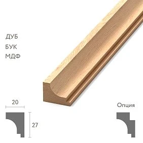
The length of the sample depends on what needs to be checked
A small fragment is enough to examine the cross-section, but a corner requires two mating parts. To check a longitudinal joint — two segments joined on a single base. An ornament requires a length on which the full motif and its repetition are visible.
Before ordering samples, it is useful to divide the material by purpose. One fragment is kept in its original state, another is used for staining, and two more — for a trial corner. This way the result of the treatment can be compared with the untouched surface, and the approved sample will not have to be cut for the next check.
There is no universal length in centimeters for all profiles. A wide complex molding and a thin smooth contour need different fragments to see their character.
They separately clarify whether the required segments can be obtained, whether a whole strip will have to be purchased, and whether the required profile is included in a ready-made demonstration set. The composition of the set is determined by the specific item, not by the general name “samples for the designer.”
Get Consultation
Each fragment is immediately labeled and checked against the drawing
On the back or on a separate tag, indicate the manufacturer, the full article number, the size version, and the date of receipt. The designations “first,” “second,” and “wide” are easy to confuse after staining or when transferring samples to the customer.
It is especially important to record the version if different sizes are offered under one article number. MLDPU-027 has variants 14 × 9 × 2600 and 20 × 12 × 2600 mm. A label with only the article number does not explain which of them was approved.
The sample is compared with the dimensional diagram: the face and mounting sides are identified, and the width and maximum overall depth dimension are checked. Measurement is carried out without crushing the surface. Permissible deviations are not invented independently — if in doubt, clarify the requirements for the specific product.
Materials from the section 3D models and drawings help verify that the file matches the selected item. If the card, drawing, and resulting fragment diverge, the cause is determined before approval. The digital model should not be adjusted to a random sample without such verification.
Equal width and different depth provide a separate test
Let us imagine three conventional profiles with cross-sections of 40 × 8, 40 × 14, and 40 × 22 mm. This is an example of geometry, not a list of STAVROS products. Each will occupy a 40 mm wide strip, but the projection relative to the common mounting plane will differ.
Such a comparison helps assess how voluminous a line the wall needs. However, greater thickness does not guarantee a more successful shadow pattern: the result depends on the cross-section, light direction, and profile placement. A smooth bead and a complex system of grooves are perceived differently at a close offset.
Dimension C usually describes the corresponding maximum overall size of the product according to the drawing. It is not equal to the depth of all recesses in the relief. Therefore, alongside the number it is useful to see the end face of the sample and its side view.
When checking near a door, the projection is additionally compared with the casing. This makes it clear whether the molding will be perceived as a subordinate contour or as an independent volumetric element.
Width is assessed through the free field of the frame
A sample in hand hardly explains how much space the profile will occupy in the composition. It is better to compare it with the actual outer size of the frame, the adjacent casing, and the furniture.
Suppose, according to the project, the outer width of the frame is 600 mm, and the inner field should be no narrower than 550 mm. A profile 20 mm wide will leave 560 mm, 22 mm wide — 556 mm, 35 mm wide — 530 mm. In this conventional example, the last option does not meet the original constraint, even if its relief is more appealing upon close inspection.
This calculation does not prescribe a universally correct molding width. It helps separate geometric constraints from taste-based choices. For a different setting, a wide profile may be appropriate.
When comparing narrow and wide options, keep the same installation height and the outer boundaries of the composition. If you enlarge the frame at the same time, it will be difficult to tell what improved the result: the new profile or the changed proportions.
A comparison requires a single test surface
Candidates are placed on the same base and in the same orientation. Ideally, their visible length should be comparable. A long line and a short offcut are perceived differently, even when the cross-section is the same.
| Condition | How to ensure comparability | What will distort the comparison |
|---|---|---|
| Base | One plane and the same preparation | Different backing thicknesses |
| Lighting | One light source and the same sample position | One profile at the window, the other deep in the room |
| Finishing | Identical preparation and coating stage | Glossy painted sample next to an untreated one |
| Direction | Position specified by the design | Random rotation of an asymmetric section |
| View | Single viewpoint and observation height | Evaluating one sample up close and the other from a distance |
When placing them side by side, ensure that one profile does not cast a shadow on the adjacent one. For an accurate comparison, they can be installed one after another in the same spot, then swapped.
At the initial stage, the temporary fastening must allow repositioning. The selected adhesive and finishing solution should be tested separately, on a designated fragment of the substrate.
Side lighting reveals the section but requires context
Under diffuse frontal lighting, some differences between profiles become less noticeable. Light along the surface emphasizes protrusions, recesses, edges, and joints. Therefore, it is useful to compare both modes.
The check is carried out under lighting close to the design conditions. If the wall frame will be illuminated by a sconce from above, its horizontal and vertical sections may look different. A single fragment lying on the table is not enough for such a solution.
A portable lamp helps to examine the geometry, but its position should not accidentally become the sole basis for the choice. Harsh light close to the wall can reveal surface features that are almost invisible under normal lighting. Conversely, bright, even illumination can hide a shadow that is important for the interior.
Record under which light source and at which position the result was observed. If daylight changes noticeably in the room, the sample should be viewed at different characteristic periods while keeping the other comparison conditions the same.
The sample is examined from a distance and in the design orientation
Up close, the edge, surface, and cleanliness of the joint are assessed. From a normal distance, check whether the line reads clearly and how active the relief becomes. The far point of the room shows the molding's contribution to the overall composition.
For a small room, you can start by viewing from about half a meter, then step back to one and a half to two meters and to the main entrance. These are guidelines for organizing the check, not regulatory distances. What matters most are the actual points from which a person will see the wall.
A shallow groove that is expressive at arm's length may blend with neighboring protrusions from a distance. Then the question is not the quality of the detail, but whether the project needs this level of relief.
The profile is also checked vertically and horizontally if it forms a frame. For an asymmetrical section, determine in advance which side faces inward. Flipping the sample changes the direction of light and shadow and can lead to an erroneous comparison of two identical details.
A casing, baseboard, and panel are needed next to the sample
Neighboring elements set the scale and the mounting plane. A molding that looks calm on its own can become the most noticeable profile on the wall next to a thin casing. This is not always a mistake, but such a relationship must be intentional.
For fitting, it is advisable to use actual fragments of the mating elements. If the molding is installed on a panel, its thickness is taken into account. For example, an 8 mm panel and a 12 mm thick profile will give a nominal projection of 20 mm from the wall, excluding the installation layer. With a casing protruding 16 mm, it is precisely the assembly that is compared: in this conditional case, it will be 4 mm ahead.
It is better to evaluate the skirting and cornice at their own heights or on a common layout with an installed molding fragment. Samples laid out side by side on a table show cross-sections but do not reproduce the distances between them.
At the junction with the panel, the edge, the free gap, and the point where the profile ends are also checked. Stylistic similarity alone is not enough for such a joint.
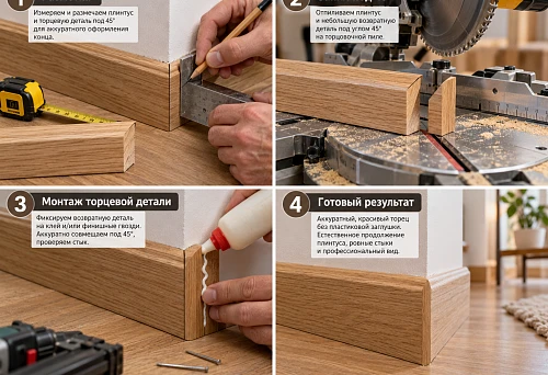
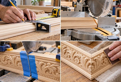
A test 45° corner verifies use in a frame
For a rectangular frame, a test corner is assembled from two pieces with 45° cuts. Check the direction of the profile, the alignment of the relief, the apex, and the appearance of the joint line. The sample should show how a straight linear molding turns into a corner.
First, the parts are fitted without final finishing. Then a separate fragment intended for this purpose is brought to the accepted technology and painted. Evaluation after coating shows how successfully the joint is made in its finished form.
A gap by itself does not yet prove a defect in the product. Its cause may be an inaccurate cut, displacement of a part, or incorrect orientation of an asymmetric cross-section. First, the preparation and assembly are checked, then a conclusion is made about the suitability of the profile.
A pair of 45° cuts relates to a 90° angle in the plane of the frame. Actual room angles are measured separately. If the profile is used on an external or internal spatial corner, a sample of the corresponding joint is required; a flat frame does not reproduce its geometry.
A longitudinal joint and a decorative corner require their own tests
On a long line, it is important to check the joint of two strips: whether the face surfaces align, whether a step appears, and how the joint looks under side light. Such a check requires two fragments on a common prepared plane.
If the base surface is uneven, the result may reflect an installation issue rather than a difference between products. Therefore, the test conditions are recorded and, if necessary, repeated on a verified base.
The finished decorative corner is evaluated together with the main molding. In the section decoration for moldings there is a selection by specific MLDPU profiles. After choosing a suitable piece, the joint point, installation planes, and orientation are specified.
A decorative corner can change the character of the entire frame. If it becomes too dominant, it is reasonable to compare it with a regular miter cut of the main profile. At the same time, the completeness, dimensions, and number of corner elements are then accounted for separately from the linear meter of molding.
Ornamental trim requires a full motif and repetition
For smooth molding, a short fragment allows you to examine the cross-section and the character of the shadow. For ornamental trim additionally check the whole motif, the direction of the pattern, and the transition to the next repeat.
A single cut leaf or scroll does not show the rhythm of a long line. To understand how repeats join, a fragment longer than one rapport—the repeating section of the ornament—may be needed. The length is chosen according to the task, not for the convenience of storing the sample.
When checking the frame, the position of the cut relative to the pattern is marked. A geometrically precise corner can join motifs unsuccessfully: for example, cutting off two noticeable elements near the apex. In that case, another layout, the provided corner decor, or a different profile is considered.
For a horizontal band, the ends and the central axis are also checked. The length of the commercial strip does not automatically equal the length of the repeat. The position of the repeats is established from the drawing or the actual product and is taken into account in subsequent cutting.
A test coating is carried out according to the project system
Color and sheen can noticeably change the impression of the chosen profile. A contrasting line reads differently from a molding matched to the wall color, and highlights emphasize areas of the surface that appeared calmer on a matte sample.
First, candidates are compared in the same finish. If the profile and coating are changed at the same time, the cause of the differences cannot be reliably determined. After choosing the preferred profile, the color options can be compared separately.
The test reproduces the agreed preparation, primer, and coating, taking into account the recommendations for the product and finishing materials. The same number of coats or a universal preparation is not assigned to all moldings based solely on the name of the material.
The result is assessed after the drying time specified for the coating. The relief, edges, joint, and match with adjacent surfaces are checked. It is advisable to keep a record of the compositions used and the application method: reproducing a successful test coating from a single photograph is considerably more difficult.
A single small coated sample shows the appearance of the chosen solution but does not confirm all the performance properties of the future finish.
Painting in the wall color does not eliminate the three-dimensional line
When the wall and molding are the same shade, the color contrast is reduced. The relief, however, continues to cast a shadow. Therefore, a deep profile in the base color can remain more noticeable than a thin contrasting outline — the result depends on the lighting and the profile itself.
For the test, it is useful to coat not only the part but also the surrounding area. A narrow white backing around a gray molding does not reproduce a gray wall: the edge of the background itself attracts attention and changes the perception of the sample.
If contrasting trim is planned, assess whether there are now too many graphic lines. Sometimes the chosen profile works, but the number of frames needs to be reduced or the additional inner contour omitted.
It is advisable to decide on width and depth together with the intended color. Otherwise, an approved raw fragment may, after painting, produce a substantially more active composition than expected on first viewing.
A wall fragment links the sample to the overall pattern
For a representative area, assemble a corner of the frame or part of a double surround with the actual gaps between profiles. Next to it, reproduce the required wall finish and the adjacent detail if the decision depends on it.
The outer boundaries of the entire composition can be marked with removable layout lines. This helps assess the size of the margins and the position relative to the furniture, although it does not replace a three-dimensional profile. The sample is installed at the specified height, not just where it is convenient to reach by hand.
If the solution involves a curved surface, verify the specifically confirmed flexible version in the required direction of bend. A small straight offcut does not show how the part will behave at the design radius or how it will join the adjacent straight section.
The fragment being tested should answer the remaining question. For a simple smooth frame, a corner and a painted sample may be sufficient. For a complex combination of panel, profile, and overlay, an assembly with the actual differences in mounting planes will be required.
The comparison is recorded against criteria related to the project
After viewing, it is useful to write down observations for each candidate. Instead of a general assessment of “beautiful,” specify what exactly works or needs changing: line width, character of the shadow, appearance of the corner, junction with the architrave.
| Check | What to include in the comparison | Basis for revision |
|---|---|---|
| Dimensions and cross-section | SKU, finish, actual end face appearance | Does not fit into the specified assembly |
| Free field | Remaining frame dimensions | Design constraint violated |
| Chiaroscuro | Observation under the specified lighting | The line is lost or dominates contrary to the intent |
| Angle and joint | Appearance before and after finishing | The joint cannot be achieved using the accepted method |
| Finish | Preparation system, color, gloss | The result differs from the agreed design intent |
| overall composition | Evaluation from design viewpoints | The profile works on its own, but overloads the wall |
Mandatory constraints are checked before subjective choice. A profile that fails dimensional requirements cannot be deemed suitable merely for its expressive shadow.
If the cause of an unsatisfactory result is unclear, repeat that specific trial. For example, reassemble the corner after checking the cut. There is no need to repeat all checks when the remaining question concerns one specific joint.
The approved sample receives a passport and a place on the display board
The selected molding, coating sample, and characteristic joint are kept on the working display board. If the project uses an additional profile, cornice, or baseboard, fragments of them can be placed nearby with clear labels.
| Passport field | What to specify |
|---|---|
| Project mark | For example, M-01 — the main wall molding |
| Product | Manufacturer and full article number |
| Finish | Material, width, thickness and commercial length |
| Finishing | Preparation, coating, color and gloss level |
| Verified assembly | Straight section, corner, joint or abutment |
| Approval | What was approved, by whom and when |
| Related data | Product card, drawing and specification entry |
A distinction is made between a demonstration fragment and the approved project reference sample. The first helps during selection, the second records the specific approved decision. It is not repainted for the next customer without preserving the required sample of the current project.
If only the shape and size have been approved, this is noted separately. An "approved" signature without clarification may be mistakenly perceived as approval of the finish, assembly unit, and installation technology at the same time.
How to order molding samples for a specific check
The request specifies item codes, dimensional versions, and tasks: comparing the relief, a trial cut, painting, or assembling a junction. Such a list helps discuss the required material format rather than receiving an arbitrary set of visually similar parts.
STAVROS offers the printed catalog KATALOG-PU, the demonstration set SOPU-001, and exhibition stands. Their composition and purpose are verified against specific items. The availability of a ready-made set does not mean that it includes all the moldings selected for your project, or that it can be disassembled for trial cuts.
To discuss the terms, you can use the section for designers and architects. It is useful to attach a fragment of the layout and indicate which question remains to be resolved.
The possibility of obtaining individual cut pieces, their sizes, cost, and lead times are clarified upon inquiry. The catalog, exhibition stand, and material for processing serve different purposes, so before ordering it is important to determine what is needed specifically for this check.
After selecting a sample, the link to procurement is retained
The selected item code and version are transferred to the 3D model, working drawings, and specification. If the physical sample showed that the previous profile in the visualization is unsuitable, the model is updated to match the actual product while preserving its dimensions.
Before buy polyurethane moldings, the cut pieces, cutting layout, and number of commercial strips are calculated. Material spent on corners and color tests is not automatically considered suitable for installation. The saved reference sample also has a separate purpose.
When proposing a replacement, check which properties have changed. A similar width does not confirm the previous depth, shadow pattern, and joint. Significant differences will require a new sample and re-approval of the relevant parameters.
It is useful to keep standard narrow, medium, wide, smooth, and ornamental profiles with readable labels in the studio's library. But before using an old sample in a new project, verify the current version and the spec card. The working value of such a library is determined by the accuracy of the labels and clear verification results, not by the number of accumulated offcuts.