Article Contents:
- Why outlets and switches should shape the molding design
- A beautiful wall is rarely an empty wall
- Solve the fixed conditions before drawing rectangles
- Molding is trim, not an electrical-box component
- Keep devices accessible and covers unobstructed
- Do not guess where hidden cables run
- Fixtures introduce heat, weight, and movement
- Separate electrical changes from cosmetic installation
- Measure the wall rather than the room name
- Treat the outer edge of each plate as the object boundary
- Make two drawings: geometry and use
- A useful sample measurement sheet
- Option 1: Keep the switch or outlet outside the frame
- Option 2: Place the device inside a larger decorative frame
- Option 3: Split the wall into separate panels
- Option 4: Use a single horizontal line instead of full rectangles
- Aesthetic breathing room is not the same as a code clearance
- Consider the space needed for cords and plugs
- Slim moldings keep small panels readable
- Medium-profile framing is often a practical compromise
- Reserve wide profiles for large, quiet areas
- Verified STAVROS profile comparison
- Mitered corners emphasize a continuous line
- Preformed corners add another dimension to the calculation
- Define the obstacles and the intended composition
- Calculate the actual pieces before buying
- Add contingency without pretending it fixes a bad drawing
- Start from the bed, not from the wall's center
- Check the cut plan against the stock length
- Avoid the common nightstand error
- Keep the center functional
- Mount the TV independently of the trim
- Preserve a useful control zone
- Look for door-swing and cleaning conflicts
- A thermostat needs its own breathing space
- Start with measured finished segments
- A three-panel example exposes the difference
- Account for corner blocks and real-world losses
- Build an order worksheet that can be audited
- Evaluate the existing finish
- Protect nearby finished surfaces
- Choose the adhesive for the actual materials
- Use the same reference on paper and on the wall
- Dry-fit the profile as a physical object
- Cut and label in deliberate groups
- Work from an established datum
- Finish seams without bridging functional joints
- Choose a finish that supports the layout
- Know when to ask for technical guidance
- A rail runs straight into a faceplate
- One panel is noticeably narrower for no good reason
- The profile is too heavy for the space
- Decorative corners occupy the only clear area
- The order was calculated by square footage
- Can I put a picture-frame molding panel around an outlet?
- Is three inches a required clearance from a switch?
- Should the switch plate be removed to glue molding?
- Can polyurethane molding conceal existing electrical cables?
- Which molding is appropriate for a narrow hallway?
- Does a decorative corner make installation easier?
- Can trim be installed over wallpaper?
- How much extra molding should I order?
- Can I put molding around a smart thermostat or wall sconce?
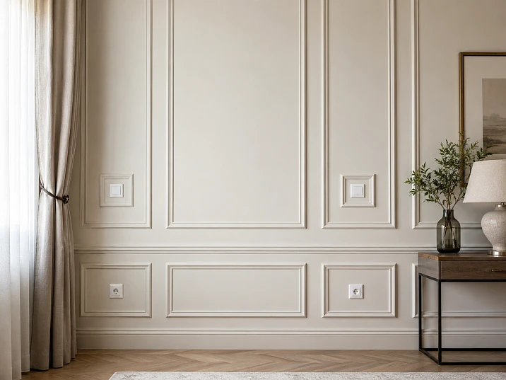
Wall molding can make an ordinary painted room feel carefully composed, but most homes have something important in the way: receptacles, light switches, thermostats, dimmers, wall sconces, and low-voltage plates. A picture-frame molding layout that looks perfect on an empty drawing can fail when the first vertical strip lands beside a switch plate or the lower rail crosses a duplex outlet. For U.S. homeowners, the solution is not to disguise electrical hardware with trim. It is to design the decorative geometry around the hardware that must remain usable, accessible, and safely installed.
This practical guide explains how to measure a wall that already has electrical devices, choose frame arrangements that accommodate them, select appropriate STAVROS polyurethane molding, and calculate the pieces to order. It also explains where a decorating project ends and licensed electrical work begins. The examples use feet and inches, realistic U.S. room layouts, and actual STAVROS product dimensions; they are planning examples, not substitute instructions for electrical installation or local code review.
For a first look at the available shapes, compare the STAVROS polyurethane wall molding collection. Then work through the steps below before choosing a profile or ordering long molding strips.

Why outlets and switches should shape the molding design




A beautiful wall is rarely an empty wall
Picture-frame molding is an applied decorative border: the finished wall remains behind it, while narrow strips establish raised rectangles or other geometric divisions. Unlike built-in paneling, those strips do not need to determine the location of every device. However, their sight lines are highly visible. A frame that almost touches a dimmer appears cramped, and a rail that stops abruptly at an outlet often looks accidental rather than intentional.
Older homes may have multiple switch positions from different remodels. New construction can have smart thermostats, combination switches, GFCI receptacles, cable outlets, security keypads, and interconnected controls. Bedroom walls may combine wall lights with nightstand receptacles. A TV wall can have a recessed media box behind a screen plus accessible outlets below the console. Those differences make a generic diagram only a starting point.
Наша фабрика также производит:


Смотреть весь Каталог продукции
Solve the fixed conditions before drawing rectangles
The goal is visual order, not mathematical perfection at every point. A switch beside a door can live in a narrow unframed strip, while two larger balanced frames occupy the remaining wall. That solution often looks better than squeezing a small ornamental frame around the switch merely to preserve an arbitrary panel count.
Получить консультацию
Molding is trim, not an electrical-box component
Applied trim should never function as a cover plate, box extender, spacer behind a device, wiring raceway, or support for an outlet or light fixture. Do not use adhesive, caulk, or paint to seal a required access point. The visible cover must remain fully functional and removable for qualified servicing. If the finish thickness changes the relationship between a device, its box, and the finished wall, consult a licensed electrician about the correct listed components and applicable requirements rather than improvising with decorative molding.
Establish a safe design boundary before taking measurements
Keep devices accessible and covers unobstructed
The most important rule is simple: keep the molded border off electrical hardware. Do not attach polyurethane strips to a faceplate, overlap a plate, fill its screw openings, or bridge across a box opening. Even a shallow relief profile can prevent a cover from seating correctly if it is placed directly against the cover's edge. An apparently harmless decorative detail may also restrict future maintenance or the use of a larger replacement plate.
There is no universal decorative distance, measured in inches, that proves an arrangement meets electrical code. Instead, establish a comfortable visual setback and confirm the device remains accessible. In the illustrations here, a few inches of clear painted wall is a design preference, not an electrical-code clearance. Hardware dimensions, manufacturer instructions, and the authority having jurisdiction take precedence.
Do not guess where hidden cables run
A switch plate does not show the complete cable route inside a wall. Wires can turn above, below, or beside boxes; plumbing may also be concealed. Avoid driving nails, screws, saw blades, or drill bits into an unverified wall cavity. For decorative polyurethane profiles, use an adhesive compatible with the profile and the prepared substrate when the manufacturer permits it. If a design requires mechanical fasteners, concealed service locations must be established before drilling. Moving wiring, mounting a sconce, and changing the electrical box are electrician work, not molding-installation shortcuts.
Fixtures introduce heat, weight, and movement
A wall sconce occupies physical space beyond its electrical box. Its shade, mounting canopy, bulb temperature, and cleaning access all matter. Keep decorative components away from the fixture's heat-affected zone and follow the light manufacturer's installation instructions. Polyurethane trim should not support a fixture, conceal a damaged electrical connection, or restrict ventilation. Similarly, do not enclose transformers, drivers, or power supplies in a homemade trim cavity simply because it looks tidy.
Separate electrical changes from cosmetic installation
If you want an outlet moved to achieve symmetrical paneling, make that decision in the design stage. Have a licensed electrician evaluate feasibility and local requirements; wait until the electrical work and any necessary inspections are complete before installing the decorative finish. If there is any sign of overheating, looseness, moisture damage, sparking, or damaged insulation, stop the cosmetic project and address the electrical issue first.
Make a wall map that an installer can actually use
Measure the wall rather than the room name
Begin with the finished wall width, floor-to-ceiling height, baseboard height, ceiling trim depth, and door or window casing. Record each item from one consistent reference point, usually the left finished corner and the floor. A wall described as twelve feet wide may have a door casing consuming four inches, an uneven corner, and a return that makes the usable trim area narrower. Draw the usable surface, not the nominal room dimension.
Measure at the floor, middle, and upper portion of the wall if the building is older. A slight change in width can matter to narrow repeated panels. Note bumps and bowed areas as installation constraints. Photograph the entire wall straight-on, then take close-ups of multi-gang plates and fixtures. A photograph makes it easier to compare the paper plan with reality, but the actual measuring tape remains the authority.
Treat the outer edge of each plate as the object boundary
Write down the left, right, top, and bottom edges of each actual faceplate. Measuring only the device center can cause a miscalculation when a three-gang switch plate is substituted for a single plate. Smart controls and thermostat displays have different footprints, so never assume a standard dimension. Mark wall fixtures by their complete installed outline, including shades and covers, not merely by the round electrical-box position behind them.
Give every device a short label: S1 for switch, R1 for receptacle, T1 for thermostat, L1 for light. Record the plate's width and height and the height of its center above the finished floor. Photograph the wall map with those labels visible so another installer can understand the decisions without reverse-engineering them.
Make two drawings: geometry and use
The geometry drawing shows proposed molding centerlines or outer edges, panel widths, and gaps. The use drawing shows furniture, door swings, wall-light illumination, furniture cords, and normal access to outlets. This second drawing catches a frequent problem: the trim may technically avoid a receptacle but still become hidden under a headboard, forcing the entire panel to look chopped off above the furniture.
For a high-traffic wall, tape the proposed border directly onto the paint using low-tack painter's tape suitable for the surface. Stand at the entry to the room and view it at night, when the controls and sconces are in their normal working environment. This inexpensive mockup catches visual problems that a scale drawing does not.
A useful sample measurement sheet
| Field | Example reading | Why it matters |
|---|---|---|
| Finished wall | 144 in wide × 96 in high | Sets the maximum composition |
| Baseboard top | 5.5 in above floor | Prevents the frame from crowding the baseboard |
| Left switch plate | From x = 17 to 21 in; y = 41 to 46 in | Identifies the occupied area |
| Door casing edge | x = 0 at the start of usable wall | Establishes the reference origin |
| Desired frame area | x = 36 through 134 in | Leaves a clear, unframed switch zone |
| Wall finish | Sound painted drywall | Determines compatible surface preparation |
These numbers are hypothetical, and the coordinates are illustrative only. The table illustrates the method, not a recommended location for any receptacle or switch. Do not relocate electrical devices to match this example.
Four ways to compose frames around existing electrical devices
Option 1: Keep the switch or outlet outside the frame
This is frequently the cleanest choice for a hallway, entryway, or wall beside a doorway. The device remains in an unframed zone near the door casing; the decorative panel begins farther across the wall. The gap can feel intentional when the frame aligns with another significant object such as a console table, mirror, or section of open wall.
Avoid creating a tiny frame solely to occupy the left-over strip. A narrow, empty piece of wall is often the visual pause that lets the main composition breathe. In a hallway with multiple switches, a restrained run of polyurethane wall molding on the wider uninterrupted section can outperform a fully covered panel grid.
Option 2: Place the device inside a larger decorative frame
A switch plate can appear within the painted field enclosed by a decorative rectangle if the trim does not interfere with the device. The frame should be large enough that the plate does not visually collide with one side. This is especially useful when an existing outlet lands near the lower portion of a large wall panel and leaving it outside would produce an awkward step.
However, an electrical device inside a decorative frame is not automatically safe or attractive. Confirm that the plate remains removable, cords can be inserted and removed normally, and a future replacement plate will have room. Think about the person using the switch with one hand and carrying groceries with the other. Decorative alignment must never defeat ordinary use.
Option 3: Split the wall into separate panels
Two tall frames with a clean center strip work well when a thermostat or intercom is centered on a wall. The control becomes part of the neutral center stripe rather than a flaw in either panel. For a symmetrical look, keep the frame widths and surrounding margins consistent whenever the fixed-device locations permit it. A larger center strip may be preferable to two very narrow outside panels.
This strategy is also useful in living rooms. The center may hold a TV, media outlets, and data ports, while framed portions of wall on either side supply the architectural rhythm. The TV mount and electrical infrastructure remain separate from the decorative strips.
Option 4: Use a single horizontal line instead of full rectangles
Not every wall requires four-sided picture frames. If a room contains outlets at multiple heights, a simple uninterrupted molding rail across an electrical-free zone can provide structure without cutting around every plate. The rail may separate upper and lower paint colors, align with cabinetry, or emphasize an existing architectural division.
Do not choose its height by copying a photo. Measure actual switches and devices first. If a horizontal band would pass through a device or even crowd the plate, shift the design or abandon the band. The best trim layout often uses less molding to avoid a visually noisy or operationally awkward result.
How much space should you leave around an outlet?
Aesthetic breathing room is not the same as a code clearance
For visual planning, try a paper mockup with around 3–5 inches of plain wall between a switch cover and the nearest visible molding edge, then adjust the distance to suit the profile, plate, and room. This is merely a starting range for composition. A slim 0.39-inch molding will appear less imposing than a 1.38-inch profile at the same separation; a broad multi-gang plate may need more visual space than a single toggle.
Some projects cannot achieve a generous visual margin. Rather than narrowing the space until the trim seems to touch the plate, make the panel smaller, reduce the number of frames, or leave that section unframed. Check the full range of device operation and do not put trim where it could complicate future servicing. Any regulatory requirement must be determined by the qualified professional responsible for the installation.
Consider the space needed for cords and plugs
A receptacle used for a vacuum cleaner or seasonal decorations needs convenient reach from the front and side. A large right-angle plug may protrude far more than an ordinary small plug. A molded frame that is too close to the cover can become a nuisance when household equipment changes. Measure the plug or adapter you actually expect to use if the receptacle is in a visible, frequently accessed location.
Choose the right polyurethane profile for a busy wall
Slim moldings keep small panels readable
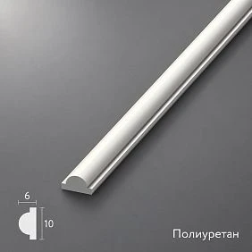
STAVROS MLDPU-001 measures 10 × 6 × 2,600 mm, or approximately 0.39 × 0.24 × 102.36 inches (face width × projection × stock length). Its fine rounded bead makes it a candidate for compact frames or a subtle secondary line. The MLDPU-001 thin polyurethane molding can keep a wall from feeling overly decorated when the same wall already contains several switches or outlets.
The limitation is scale. A narrow line may almost disappear on a broad wall viewed from across an open-plan living room. If you want the profile to register visually at twenty feet, evaluate a wider option with a full-size taped sample, rather than assuming the smallest item always looks more refined.
Medium-profile framing is often a practical compromise
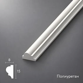
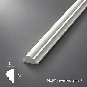
STAVROS MLDPU-004 is 15 × 8 × 2,600 mm (approximately 0.59 × 0.31 × 102.36 inches). Its compact relief is useful where the trim needs a visible edge without becoming the primary focal point. Look at the MLDPU-004 decorative molding profile for a more pronounced line than MLDPU-001.
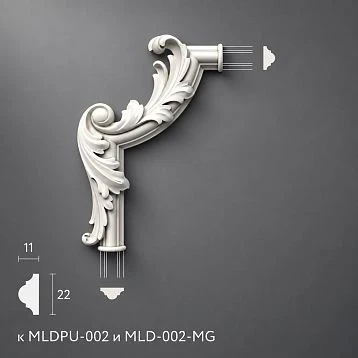
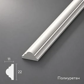
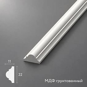
MLDPU-002 is 22 × 11 × 2,600 mm, equivalent to approximately 0.87 × 0.43 × 102.36 inches. Its stepped contour creates a stronger shadow. For a larger wall that has one or two devices but generous open areas, MLDPU-002 polyurethane panel molding can provide a clear main frame without requiring an oversized profile.
Reserve wide profiles for large, quiet areas
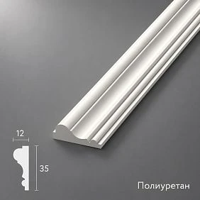
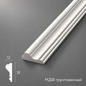
MLDPU-003 measures 35 × 12 × 2,600 mm—roughly 1.38 × 0.47 × 102.36 inches. This is a visually substantial molding. It can be effective around a tall accent panel but may feel crowded next to a four-gang switch plate or a narrow doorway. Compare the MLDPU-003 wide panel molding on the actual wall rather than relying on a magnified product picture.
MLDPU-027 offers two half-round options: 14 × 9 mm and 20 × 12 mm, each 2,600 mm long. The smaller version is approximately 0.55 × 0.35 inches in section, while the larger is 0.79 × 0.47 inches. These smooth, rounded lines can work in restrained interiors that need softer shadows; compare the MLDPU-027 half-round molding with sharper stepped contours.
Verified STAVROS profile comparison
| Product | Width × projection | Stock length | Suggested decorative use |
|---|---|---|---|
| MLDPU-001 | 0.39 × 0.24 in (10 × 6 mm) | 102.36 in | Delicate frames or secondary lines |
| MLDPU-004 | 0.59 × 0.31 in (15 × 8 mm) | 102.36 in | Compact main frames in entryways |
| MLDPU-002 | 0.87 × 0.43 in (22 × 11 mm) | 102.36 in | Medium-size panel borders |
| MLDPU-003 | 1.38 × 0.47 in (35 × 12 mm) | 102.36 in | Large feature panels with open wall space |
| MLDPU-027 | 0.55 × 0.35 or 0.79 × 0.47 in | 102.36 in | Soft, half-round outlines |
All dimensions above come from the published STAVROS product listings. The suggestions are design interpretations, not manufacturer claims about electrical suitability. None of these decorative profiles should touch or replace an electrical box, faceplate, or fixture mount.
Decide whether decorative corners will help or crowd the layout
Mitered corners emphasize a continuous line
A standard picture-frame layout uses four straight runs joined at mitered corners. Visually, this creates a continuous border without a large accent where the directions change. It is often the most forgiving look when a wall has several outlets or a thermostat, because the frame corners do not become competing focal points. Still, mitering demands careful marking and accurate cuts. Test the actual profile's orientation and the saw setting using scrap before cutting the longest pieces.
Preformed corners add another dimension to the calculation
STAVROS has matching decorative corner elements in the molding corner and accent collection. The MLDPU-004U decorative corner corner is listed at 135 × 135 × 10 mm (approximately 5.31 × 5.31 × 0.39 inches) and is designed as a decorative turn for the MLDPU-004 series. A preformed corner changes the visible geometry and the required length of each connecting straight piece; it should not simply be added on top of a cut list designed for four miters.
For the intermediate profile, also compare the MLDPU-002U corner. A second option is the MLDPU-001U decorative corner for the finer 001-series language. Before mixing corner pieces with straight strips, confirm that the selected versions, profiles, and sizes are intended to connect and that the ornamental corners will not approach any nearby electrical cover.
Example layout A: a twelve-foot wall with a switch near the door
Define the obstacles and the intended composition
Imagine a painted wall 144 inches wide and 96 inches high. A switch plate occupies x = 17 to 21 inches from the left boundary and y = 41 to 46 inches from the finished floor. Those dimensions are only a hypothetical coordinate example. The door casing ends near the left side. Instead of placing three evenly spaced frames across the full width, use two tall rectangles in the uninterrupted portion of the wall.
Place the first rectangle between x = 36 and 81 inches, and the second between x = 89 and 134 inches. Give both the same vertical extent: from y = 25 to 86 inches. Each resulting border is 45 inches wide × 61 inches tall, measured to the chosen reference line for cutting. The switch remains clearly outside the framed composition in the left unframed zone. An eight-inch gap separates the frames. These are design coordinates, not minimum legal electrical offsets.
Calculate the actual pieces before buying
Each frame requires two 61-inch vertical pieces and two 45-inch horizontal pieces. For two frames, the cut list is four 61-inch lengths and four 45-inch lengths: 424 linear inches, or about 35.33 linear feet. A simple division by a 102.36-inch stock strip gives 4.14, suggesting five strips if material could be used without length constraints. That would be misleading.
A 61-inch cut cannot share one strip with a 45-inch cut: 61 + 45 = 106 inches, even before saw kerf. Four stock strips are therefore occupied by the four long vertical pieces. The four 45-inch horizontals fit two per strip, consuming two more stock strips. The practical cutting plan is six strips, not five. This assumes the dimensions are compatible with the chosen miter reference and leaves allowance within each stock length for normal kerf; confirm cuts from a physical sample.
Add contingency without pretending it fixes a bad drawing
Six is the minimum for this exact cut allocation. If this is your first installation or the wall is uneven, order an extra compatible strip if available and practical. Spare material protects against cutting mistakes; it does not make an infeasible panel arrangement suddenly work. Check all line positions against the actual switch cover and door swing before placing the order.
Example layout B: a bedroom wall with sconces and bedside outlets
Start from the bed, not from the wall's center
On a bedroom accent wall, the bed and headboard establish the dominant geometry. Sconces may sit on either side, while receptacles serve nightstands. A decorative composition that is symmetrical around the entire wall may not be symmetrical around the bed if the furniture is offset for a closet door. Decide what the viewer should perceive as the center: the bed, the space between sconces, or the room itself.
For a hypothetical arrangement, imagine two identical wall frames, each 31 inches wide × 55 inches tall, placed beyond the main headboard field. The installed sconces are outside the trim and retain appropriate access and clearances specified by their own manufacturers. The bedside outlets are also outside the raised lines and accessible behind the furniture. Nothing in the panel system attaches to the lighting fixtures.
Check the cut plan against the stock length
Two 31 × 55-inch rectangles require four 55-inch pieces and four 31-inch pieces. Their combined length is 344 inches, or about 28.67 feet. One 55-inch piece and one 31-inch piece total 86 inches, so each 102.36-inch strip can supply that pair with room for a typical miter saw kerf. Four strips provide the planned eight pieces. Include a spare according to your tolerance for waste and availability, but do not replace a cut plan with a generic percentage alone.
Avoid the common nightstand error
The lower side of a decorative frame may disappear behind a nightstand or headboard. This is not necessarily wrong, but it should be intentional. If the frame begins just above the furniture top, the composition remains visible and simple to clean. If the frame extends behind a nightstand, confirm that cords and the outlet plate can still be reached normally and that the molding cannot catch on furniture when it is moved.
Example layout C: a television wall with a crowded media area
Keep the center functional
A living-room TV wall may contain a television mount, low-voltage ports, a power receptacle, a soundbar, and a media console. Framing all of these items inside a tight decorative rectangle may amplify the clutter instead of improving the room. A better approach is often to reserve the screen and cable area as one uncluttered center field, then use two vertical molding panels on the left and right to frame the overall composition.
For an example layout, make the two outside panels 28 inches wide × 70 inches tall. Each panel uses two 70-inch verticals and two 28-inch horizontals. Four long verticals plus four short horizontals total 392 inches of decorative trim. Unlike the earlier 61/45 example, a 70-inch cut and a 28-inch cut can share the same 102.36-inch strip: 70 + 28 = 98 inches. With properly planned miter references and a suitable saw kerf, four strips can produce the eight sides. Verify a sample cut before relying on this tight allocation; an extra strip is sensible for errors.
Mount the TV independently of the trim
Do not fasten a television bracket through a decorative molding strip as though the polyurethane were a structural support. Follow the TV-mount manufacturer's instructions for the actual wall construction and suitable structural attachment. Any new wiring or recessed electrical box must be dealt with separately by a qualified installer. If the TV wall will also include wood slats, review the layout principles in the STAVROS TV accent wall and molding guide, then coordinate the finished decorative layers before fixing the mount position.
Example layout D: a hallway with doorbell controls and grouped switches
Preserve a useful control zone
An entryway frequently places the doorbell chime, a thermostat, and multiple switches near a door. It can be tempting to squeeze a thin panel into every remaining strip of wall. In reality, one continuous neutral area around the controls often makes a calmer impression. Put the main molding panels farther along the corridor and use the unframed section as an intentional transition between door casing and architectural trim.
Hallway surfaces are commonly seen at an angle and from several distances. A heavily layered profile can cast distracting shadows when the wall is only a few feet from the viewer. For a relatively narrow corridor, consider one or two slim frames or even a single running line. The STAVROS hallway molding ideas offer additional approaches for long walls, doorways, and narrow areas.
Look for door-swing and cleaning conflicts
A door can swing toward the wall or contact a wall-mounted stop. Decorative trim should not be placed where the door handle repeatedly strikes it, and a panel corner should not interfere with a properly functioning doorstop. In hallways, also consider bags, coat hooks, and vacuuming. Applied molding can be attractive without becoming a projecting obstacle at shoulder height or a fragile edge next to the floor.
A thermostat needs its own breathing space
Some thermostats measure surrounding air, and manufacturers specify placement conditions for accurate sensing. Do not wrap a thermostat in an enclosure, obstruct its vents, or place a decorative shelf or heavy molding immediately against it. Read the particular control's instructions. If it sits in the middle of your desired framed zone, split the frames or adjust their scale rather than building a decorative surround that alters the thermostat's environment.
Calculate molding quantities using a cut list, not only linear feet
Start with measured finished segments
Total perimeter is useful for budgeting, but it is not a sufficient order quantity for long, rigid profiles. Each side of a picture-frame panel must be cut from a stock piece with enough length to accommodate the required miters. A 102.36-inch strip cannot produce a 68-inch cut and a 35-inch cut: together they require 103 inches even before the saw removes material. The mismatch looks minor on paper and becomes absolute on the cutting bench.
Prepare a cut list sorted from longest to shortest. Record the measurement convention for the corners—outside long point, inside short point, or centerline—and keep it consistent. Test the first pair of mitered pieces against the actual layout. Then allocate pieces to stock lengths like a packing problem. Do not assume every offcut can be reused, especially when the profile is directional or the required miter orientation matters.
A three-panel example exposes the difference
Suppose a separate wall composition calls for three rectangles, each 35 inches wide by 68 inches tall. The finished cut list contains six 68-inch verticals and six 35-inch horizontals. The total is 6 × 68 + 6 × 35 = 618 inches or 51.5 linear feet. Dividing 618 by 102.36 and rounding up gives seven stock strips, an attractive but impossible purchasing estimate for this cutting pattern.
Each 68-inch vertical consumes its own strip because 68 + 35 = 103 inches, slightly more than the available 102.36. That means six strips for the verticals. Two 35-inch horizontals fit comfortably on one strip, so the six horizontal pieces require three more strips. The executable allocation is nine strips. The sample leaves offcuts, but they cannot solve the specific long-piece problem. Add waste or a spare after this allocation, not in place of it.
Account for corner blocks and real-world losses
Build an order worksheet that can be audited
| Item | Quantity or measurement | Planning note |
|---|---|---|
| Finished verticals | Count and length of each segment | Measure using one miter convention |
| Finished horizontals | Count and length of each segment | Keep similar pieces together |
| Stock pieces | Minimum from the cut allocation | Not just total inches divided by stock length |
| Decorative corners | Actual count and model | Recalculate straight runs if used |
| Adhesive and joint finishing | Per manufacturer instructions | Check substrate and paint compatibility |
| Optional spare strip | Based on risk and availability | Useful when stock is hard to replace |
Prepare the wall before installing decorative trim
Evaluate the existing finish
A molding installation is only as durable as the surface to which it is bonded. Inspect painted drywall for peeling paint, powdery patches, water stains, loose joint compound, and movement. Repair underlying moisture problems before decorating. A coating that is unstable, dirty, or highly glossy may require preparation compatible with the adhesive system. Decorative trim cannot stabilize a damaged wall or prevent recurring water intrusion.
If the wall has wallpaper, identify whether the adhesive can bond to a suitable exposed substrate instead of merely to a potentially removable wallpaper layer. A framed wallpaper inset is typically easier to plan when the trim attaches to an adequately prepared solid surface and the wallcovering is fitted within it. For a related project, see wallpaper panels with decorative molding.
Protect nearby finished surfaces
Cover floors and furniture, and use painter's tape as needed around decorative areas. Do not caulk a switch or receptacle cover into place; do not paint over removable cover screws or vents. If a faceplate requires removal for a separate finishing operation, follow appropriate electrical safety procedures and the device manufacturer's instructions. Where an electrical task is outside your competence or the local rules require it, engage a qualified electrician. There is no reason to remove a live device merely to mount trim several inches away on painted wall.
Choose the adhesive for the actual materials
The adhesive needs to be suitable for both the polyurethane molding and the existing wall finish. Check the particular product's technical information for working time, surface preparation, curing, and paint compatibility. The STAVROS installation and finishing materials section is a useful starting point for product research; it is not a substitute for reading the manufacturer's current instructions for the material you buy.
Avoid assuming that any construction adhesive is appropriate. Some chemistries can attack certain decorative materials or stain finished surfaces. Test on a short offcut or an inconspicuous prepared area where necessary. Plan temporary holding methods that do not damage the wall or introduce fasteners into unknown concealed services.
Transfer the drawing and dry-fit every frame
Use the same reference on paper and on the wall
If your plan measures from the left finished corner, establish that same zero point on site. Mark both ends of the first horizontal and vertical, then check level, plumb, and the relationship to the switch plates. Use a long straightedge, laser level, or reliable spirit level as appropriate. Walls may not be perfectly square; prioritize the visible alignments that make the room look balanced while documenting any intentional adjustments.
On taller frames, check the diagonals of the layout. Equal diagonals indicate a rectangle when the opposite sides have the intended lengths. Do this before applying adhesive. A molding frame can look plausibly square while its corners are enough out of alignment to make miters separate under paint.
Dry-fit the profile as a physical object
Drawings often mark only a centerline. A molding strip has real face width and projection, so confirm where its outermost edges will land relative to each faceplate. Temporarily hold one length in the proposed position and view it from across the room. Does the trim compete with the device? Can a user operate the control naturally? Is the cover still completely accessible? If the answers are not satisfactory, adjust the layout before cutting the entire set.
For decorative corners, place an actual corner sample on the wall and mark the full silhouette. The visible footprint may be much larger than the width of the straight strip it connects to. This is particularly important beside a thermostat, sconce canopy, or multi-gang switch.
Cut and label in deliberate groups
After confirming the layout, cut one complete frame and dry-fit it. Label pieces discreetly on the back: upper, lower, left, and right. For repeated panels, mark the panel number as well. This prevents an installer from accidentally swapping slightly different pieces on a wall whose nominally equal frames required small adjustments for crooked corners.
Use tools and blade types appropriate to the profile manufacturer’s recommendations, and follow ordinary eye, dust, and tool safety practices. Keep cutting operations away from live electrical equipment. The work should focus on shaping the decorative strip—not trimming, drilling, or modifying electrical boxes.
Install, finish, and paint without compromising the hardware
Work from an established datum
A straightforward installation sequence is to set the primary horizontal or vertical reference, verify the first corner, then complete a full frame before moving to the next. The exact order depends on the profile geometry and adhesive instructions. Use compatible adhesive on the designated bonding areas, press to the prepared surface, and hold the pieces in place as required during cure. If the wall is bowed, do not force a rigid strip into a severe bend that the product has not been designed to accommodate.
Inspect each miter and seam as you go. A very small change in one corner can accumulate across repeated panels. Before the adhesive cures, check straightness, equal gaps, and the relationship to electrical covers one last time. This is the point to correct a cosmetic alignment—not after paint has hidden the pencil marks.
Finish seams without bridging functional joints
Use a filler or paintable finishing material compatible with the decorative profile and surrounding coating. Sand carefully after it cures, and remove dust before painting. Around the perimeter of a decorative strip, a controlled paintable joint treatment may improve the finished appearance when recommended for that system. It must not extend onto electrical covers, block ventilation, or bond a removable device plate to the wall.
A fixture canopy, outlet cover, or thermostat housing should remain distinct from the molding. If the proposed detail requires filling an unattractive gap in electrical equipment with decorator's caulk, redesign the molding rather than hiding the problem.
Choose a finish that supports the layout
Painting molding the same color as the wall can make the architecture feel calm, which is useful when electrical devices already interrupt the surface. A contrast color emphasizes every frame line, including small inconsistencies around plates. On a wall with several visible switches, tone-on-tone is often the easier route to a polished result. In a large formal room, stronger contrast can work if the panel geometry is sufficiently simple.
Use the paint preparation recommended for the product and for the existing substrate. Confirm any primer requirement, check coverage on an offcut, and avoid coating hardware or sealing moving parts. A photograph of the dry-fitted design and the exact product codes in your project file will make later maintenance much easier.
Know when to ask for technical guidance
Installation techniques vary with the particular material and wall type. The STAVROS finishing and installation advice can help you identify the manufacturer's general guidance. For decisions about electrical clearances, boxes, wiring, and fixture mounting, use licensed local professionals and the applicable requirements—not a decoration article or the dimensions of a molding profile.
Common mistakes that make an outlet wall look unfinished
A rail runs straight into a faceplate
This usually starts with a plan drawn before the devices were measured. The correct response is not to notch a strip around the plate or stick trim to the plate's edge. Move the decorative rail, change the panel dimensions, or switch to a simpler configuration. A continuous, safely separate decorative line will look better than an improvised joint directly against electrical hardware.
One panel is noticeably narrower for no good reason
It is reasonable to vary panel widths when architecture requires it, but the variation should have a visible logic. When one frame is half the width of its neighbor simply because a switch was overlooked, the design looks like a mistake. Use the control location as a deliberate boundary, or regroup the wall into fewer larger frames.
The profile is too heavy for the space
A broad molding can make an eight-foot ceiling and a short hallway feel cluttered. A narrow profile may be preferable, especially close to door casing and switch plates. Compare actual samples rather than picking by product photograph alone. The STAVROS molding catalog includes different cross-sections that can be evaluated side by side.
Decorative corners occupy the only clear area
Corner appliques need physical room. An ornamental turn may project near a sconce or overlap the open space intended for a control. If that happens, use a simple mitered junction rather than squeezing the ornament into place. A less complicated detail is often the more enduring design choice.
The order was calculated by square footage
Square footage is relevant to paint or wallpaper, not to the length and cut pattern of molding strips. Always count each finished length and allocate pieces to the supplier's stock dimensions. A miscalculation becomes more expensive when the replacement part must be shipped separately or comes from a different production batch.
Questions homeowners ask before ordering
Can I put a picture-frame molding panel around an outlet?
You can design a decorative panel so the outlet appears within the painted area, provided the molding does not interfere with the electrical device, its cover, normal use, or maintenance. Keep the trim independent of the equipment and confirm any electrical requirements through the appropriate local professional. Do not glue the trim to the outlet plate.
Is three inches a required clearance from a switch?
No. The example distances in this article are visual-design starting points, not an electrical-code rule. The correct plan depends on the actual device, required access, surrounding finish, fixture instructions, and local requirements. Use the full outline of the plate in your drawing and allow practical working room around it.
Should the switch plate be removed to glue molding?
Not when the molding can be installed safely on the adjacent prepared wall without disturbing the plate. Never work on energized wiring or remove devices as a decoration shortcut. If the cover or device must be handled for a separate task, follow appropriate safety procedures and involve a licensed electrician when necessary.
Can polyurethane molding conceal existing electrical cables?
Do not treat a decorative polyurethane profile as a wiring raceway. Concealing or routing wiring involves products and methods intended for electrical use and may require code-compliant installation by a qualified professional. A molding strip chosen for its appearance does not become a listed cable-protection system simply because it is hollow or stands proud of the wall.
Which molding is appropriate for a narrow hallway?
For a restrained look, compare a fine profile such as MLDPU-001 or the slightly more pronounced MLDPU-004 against the available wall space. View the sample at typical hallway distance and check how its full width relates to nearby plates and door casing. The best choice depends on scale and style, not on a universal width requirement.
Does a decorative corner make installation easier?
A matching corner can create a finished ornamental turn, but it also changes the cut list and the footprint of the frame. Confirm compatibility with the straight profile and the dimensions from product drawings. The STAVROS molding accent options are useful for comparing the different corner styles; do not assume that all corners fit all moldings.
Can trim be installed over wallpaper?
The adhesion of any assembly depends on its underlying surface. If the wallpaper itself is not securely attached or is not an approved bonding substrate, adhesive applied to the wallpaper cannot make that system dependable. Determine the substrate and product requirements before committing to the sequence. Fitting wallpaper inside trim that is bonded to a sound prepared surface may be more practical for many projects.
How much extra molding should I order?
First calculate the stock allocation from the actual lengths you need. Then add allowance for kerf, test cuts, damaged ends, and reasonable mistakes. Ten or twenty percent is a rough shopping buffer, not a substitute for a piece-by-piece cutting plan. Some layouts need a full extra strip even when their total linear footage appears comfortably covered.
Can I put molding around a smart thermostat or wall sconce?
Only as separate wall decoration that leaves the equipment operable and compliant with the relevant manufacturer's instructions. Do not block thermostat vents or sensor openings, restrict a sconce's heat clearance, or use trim to support the fixture. If the proposed panel crowds the device, leave that area undecorated or redesign the frame.
Final plan: make the wall work before making it decorative
The successful sequence is straightforward: measure fixed devices; establish the usable wall fields; choose a restrained frame layout; check the profile at full scale; create a real cut list; prepare the surface; and install the trim without disturbing electrical equipment. This order prevents the common mistake of buying molding for a beautiful drawing that cannot be installed cleanly on the actual wall.
Before ordering, save your dimensioned plan, photographs, product code, exact profile size, cut allocation, and notes about any existing damage. Review the STAVROS polyurethane molding selection with those measurements in hand. Confirm product availability, packing, current finish recommendations, and shipping terms with STAVROS for your destination rather than assuming a domestic U.S. warehouse or a guaranteed delivery schedule.
The strongest result is not necessarily the wall with the most decorative strips. It is the one where panels, switch plates, lighting, doors, and furniture all seem to have been considered together, and where the finished molding remains clearly separate from the systems that make the room function.