Article Contents:
- MLD-040 80×12 mm: what exactly the assembler purchases
- Why the face width is the key dimension of the central unit
- Why the 12 mm thickness also matters
- Why the product page does not answer the question about paired doors
- What to measure
- Why the door leaf width hardly helps
- Position of the frames
- Extensions and installation joints
- Design gap between two profiles
- Non-parallelism of openings
- Finishing of the central wall
- Why overlapping changes the architecture
- Why longitudinal trimming is not a neutral operation
- To whom an unresolved junction is returned
- Type A — standard
- Type B — borderline
- Type C — narrow
- Type D — asymmetric
- What it means to “check every pair” without 24 manual projects
- Why a single measurement is not representative
- What to check with the template
- Why one tape-measure mark is not enough
- How to use the template on 24 pairs
- Why it is important to open both doors
- What should be considered the result of the reference standard
- Why a type A reference standard does not confirm type B
- Why you cannot simply shorten the central posts and leave the top as it was
- How to store upper elements in the specification
- Scenario A: two full MLD-040 units are retained on the central partition
- If both sides of the doors are finished identically
- Why the central posts are still labeled separately
- Scenario B: a boundary partition requires a separate tolerance
- Why a border node is dangerous to consider a standard
- How to assign a status
- Scenario C: two full-size MLD-040 units do not fit
- What must not be done without an approved decision
- Why this type should not be included in a general order as six standard parts
- Scenario D: an asymmetric pair requires its own specification sheet
- Why type D cannot be treated as type A “with one correction in meters”
- How to encode
- When longitudinal processing can be considered at all
- Why longitudinal cutting should not be included in the estimate by default
- Why the pier width is better stored as a number, not just as a type
- Why status matters
- Why the formula “48 × 3 parts” cannot be used automatically
- The number of parts matters more than the number of doors
- A door with casing on only one side is a separate complete-set type
- Why this matters for double doors
- How to encode the side
- Why such coding is useful for reordering
- A door with casing on both sides doubles not the meters, but the sets of specific parts
- Why two sides of the same door can have different lengths
- When two sides can be combined in cutting
- Central posts must be labeled as a separate class of parts
- Why all verticals of the same length cannot be stored in a common bundle
- When the outer and central posts can still be combined
- Example MDF 2600 mm
- Example vertical 2050 mm
- Why you can't cut the upper parts first
- Cutting sequence
- Conventional vertical 2480 mm
- Conventional vertical 2320 mm
- Why you can't recalculate using only a length coefficient
- Short offcuts can be used between pairs, but only within a compatible group
- What should match
- For oak with a clear finish
- What not to do
- Type A
- Type B
- Type D
- Why this calculation is stronger than “48 doors × 3”
- What happens with 2600 mm MDF
- How many long strips block the verticals
- How to lay out the 920 mm upper parts
- Why simple division gives a false minimum
- Why this is not a universal number for MLD-040
- Two unresolved Type B pairs must be counted after approval, not “add average consumption”
- Why the 22 m preliminary budget can still be kept
- How to include type B in the overall cutting plan after the decision
- Exception pairs cannot be dissolved into the average consumption of the standard series
- Why it is better to calculate the exception after the standard
- Example I-01 at the column
- Why the exception cannot be calculated in advance as “minus 270 mm”
- Reserve of long verticals
- Reserve of upper parts
- Reserve of the central unit
- Operational reserve
- What is included in the kit card
- Why the kit can be assembled without a separate box
- What to check
- An inventory count is needed before reordering
- 1. Ordering MLD-040 for just 48 doors
- 2. Not measuring each central pier
- 3. Treating 80+80=160 mm as the finished standard
- 4. Reducing MLD-040 lengthwise without a project
- 5. Mark out two doors independently
- 6. Do not assemble a reference pair
- 7. Cut the upper parts first
- 8. Calculate the reserve only in linear meters
- 9. Mix MDF and solid wood in one bill of materials
- 10. Do not flag exception pairs
- 11. Do not label the central posts
- 12. Do not recalculate the purchase after changing the door unit
- 13. Place a reorder using the words “10 more pieces”
- When another profile may be more appropriate
- Product line
- Project appendix
- Final algorithm
- What size is MLD-040?
- Why is MLD-040 called molding and casing?
- Can MLD-040 be used around a door?
- What is the face width of MLD-040?
- What is the profile projection?
- How much space do two MLD-040 need between adjacent doors?
- Is a 160 mm wall pier sufficient?
- Can two casings be overlapped?
- Can MLD-040 be shortened lengthwise?
- Do all 24 pairs need to be measured?
- How should the top parts be calculated?
- Why are long verticals reserved first?
- Can beech and oak be mixed?
- How should the leftovers be counted?
- What margin is needed?
- Can the remaining stock of one pair be transferred to another?
- How should the central posts be marked?
- How to place an additional order?
- Where can I check the current availability and price?
- Why is the price of one strip not equal to the cost of a finished pair of doors?
- What should be kept after handing over the project?
- When should purchasing be stopped?
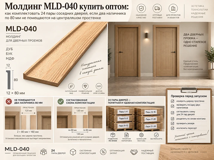
The project includes 24 pairs of adjacent doors — 48 openings in total. MLD‑040, 80 mm wide, has already been selected for the trim. On a single door, this task seems simple: two verticals and a top piece form the usual frame. But paired openings have a central pier between the frames. If you try to install two full MLD‑040 profiles on it, their face width alone takes up 160 mm — even before checking the actual position of the frames, installation seams, extensions, non-parallel openings, and the design gap between the profiles.
Therefore, buying MLD-040 moulding wholesale is only correct after classifying all 24 pairs by the actual geometry of the central zone. The main mistake is to first order material “for 48 doors” and leave the central unit to the installers. In that case, on site they start ripping the profile lengthwise, shifting it relative to the frame, overlapping two pieces, or changing the top line. For a serial project, this turns one unresolved detail into dozens of repeated reworks.
Working sequence: as-built dimensions of door pairs → width of the central pier → actual frame planes → pair type → approved central unit → finished verticals and top pieces → 2400/2600 mm material → cutting plan → number of full strips → marking of central posts → floor-by-floor kitting → reserve → wholesale order.
Main principle:
48 doors do not yet mean 48 identical sets. First, it is determined how MLD‑040 works on each pair of openings, and only after that does the number of doors turn into the quantity of parts and commercial strips.
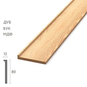
MLD-040 80×12 mm: what exactly does the order picker purchase
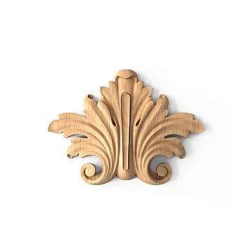
The current STAVROS product page lists MLD-040 as a wooden moulding / casing. A single profile is produced in several material versions.
| Material | Section | Product length | Grinding quality |
|---|---|---|---|
| MDF | 80×12 mm | 2600 мм | «Prestige» |
| Beech | 80×12 mm | 2400 мм | «Prestige» |
| Oak | 80×12 mm | 2400 мм | «Prestige» |
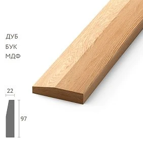
The product itself can be checked on the product page MLD-040 80×12 mm. For the purchasing article, three parameters matter: the face width of 80 mm, the projection of 12 mm, and the original length of 2600 mm for MDF or 2400 mm for beech and oak.




Why the face width is the key dimension of the central unit
It is precisely the 80 mm that determines how much of a strip the profile occupies on the wall around the frame. If two openings stand next to each other, the central zone must accommodate not one but two casings — one for each door, if that is the scheme approved by the project.
Our factory also produces:

Why the 12 mm thickness also matters
Frontally, the unit can be checked with an 80 mm wide strip. But the final fitting must take into account the 80×12 mm volume: the profile casts a shadow, projects above the wall plane, and interacts with the skirting board, upper elements, switches, and adjacent finishing elements.
Get Consultation
Why the product card does not answer the question about double doors
The card confirms the profile itself. But it does not know the actual width of your wall pier, the position of the frames, the wall finish, or how the central composition should look. This data appears only in the project specification.
The key dimension of the article is the width of the central wall pier, not the width of the door leaf
For a single opening, the free wall on the left and right usually provides space for the casing. In a pair of doors, the outer sides may be standard, while the central zone becomes critical.
The set includes:
- outer left vertical of the first door;
- central right vertical of the first door;
- central left vertical of the second door;
- outer right vertical of the second door;
- upper part of the first door;
- upper part of the second door.
It is the two central verticals that require verification of compatibility with the actual wall pier.
What to measure
It is not enough to write down “wall pier 172 mm”. You need to understand between which points the number was obtained:
- between the outer edges of the frames;
- between the intended lines of the inner junction of the architraves;
- between the finished surfaces of the reveals;
- between the extension jambs;
- between the visible edges of the door units.
For purchasing, the geometry used is the one on which the MLD‑040 will actually be located.
Why the door leaf width hardly helps
Two doors each 800 mm wide may have a central wall section of 190 mm, 165 mm, or 130 mm — this depends on the project and the actual installation of the frames. The door leaf does not determine the free space between the casings.
The formula “80 + 80 = 160 mm” is only the first check
Two MLD‑040 profiles have a total face width of:
80 + 80 = 160 mm.
But one cannot conclude:
“a 160 mm wall section means two casings will definitely fit.”
160 mm is a signal to check. The actual assembly also depends on several other parameters.
Position of the frames
If the frames are not positioned symmetrically relative to the wall section, one casing may require more usable wall strip than the other.
Extensions and installation gaps
The line of the inner edge of the casing is determined not by an abstract wall axis, but by the actual door system. If the extension protrudes or the frame is recessed, the visible strip changes.
Design gap between two profiles
Even if 160 mm fits arithmetically, the design may require a visible gap between the two central posts. Its size cannot be invented universally: it is approved on the specific assembly.
Non-parallelism of openings
At the top, the pier may be 168 mm, at the bottom — 162 mm. If you rely on a single measurement, the two long posts will start to converge or diverge.
Finishing of the central wall
A panel, tile, or another layer can change the actual plane and the visible width of the section. Therefore, the final check is done based on the finished geometry or on reliable as-built dimensions.
If the central pier is narrower than two MLD-040, the installer must not resolve the assembly on their own
Suppose the actual working width between the installation lines of the two architraves is 146 mm. Two full-size MLD‑040 require 160 mm even without an additional gap. This means the standard scheme physically does not fit.
Cannot be done automatically:
- overlay two profiles on top of each other;
- rip 7 mm off each along the length;
- reduce one casing more than the other;
- shift both away from the door frames;
- resolve the conflict with filler;
- change the upper parts only on site.
Why overlapping changes the architecture
One profile will end up higher than the other, or a step will appear. The central zone will become visually heavier than the outer sides, and the two doors will no longer be perceived as an equal pair.
Why longitudinal trimming is not a neutral operation
MLD‑040 is a finished 80×12 mm profile. Longitudinal reduction can change the edge, the decorative composition, and the width of the contact zone. Such a solution cannot be turned into a standard operation without a separate drawing and sample.
To whom the unresolved junction is returned
To the designer, architect, or door unit engineer — the one responsible for the integrity of the composition. The purchaser must identify the impossibility of the usual scheme before ordering, rather than inventing a new profile from MLD‑040 on site.
Four types of paired doors turn 24 pairs into a manageable schedule
Convenient to split pairs by central geometry.
| Type | Situation | Status of standard two MLD‑040 | Action |
|---|---|---|---|
| А | Wide pier | Fit according to the design scheme | standard set |
| Б | Boundary pier | Full-size verification required | Template / reference pair |
| В | Narrow pier | Standard scheme does not fit | Separate design solution |
| Г | Asymmetric pair | One side is constrained | Separate statement |
Type A — standard
After verification, the two central posts remain fully valid MLD‑040. The pair of doors can be replicated as a single installation kit.
Type B — borderline
The wall section is theoretically sufficient, but the margin is small or the geometry is unstable. Without a physical template and a height check, such a pair is not sent to mass cutting.
Type C — narrow
Two full-size profiles do not fit. This is not a “bad measurement,” but a separate design task.
Type D — asymmetric
The center may be normal, but one outer side abuts a corner, cabinet, switch, or another structure. The pair kit is no longer equal to Type A.
Why all 24 pairs cannot be considered one type before as-built verification
On the plan, doors may look identical. After construction, the geometry changes due to actual work.
Causes:
- plaster thickness;
- position of the frame in the opening;
- different extension;
- local tile or panel;
- offset of one opening;
- column;
- a built-in wardrobe;
- switch near the outer jamb;
- different finished wall level.
What does “check every pair” mean without 24 manual projects
You need to take the key as-built dimensions of each pair, and then group matching situations. If 18 pairs are identical, they become type A. The remaining six get B, C, D, or an individual code.
Why a single measurement is not representative
Even if the first pair fits perfectly with a 180 mm pier, this is not proof for the last pair on another floor. A wholesale specification must rely on the range of actual dimensions, not on one lucky example.
A full-size 80×12 mm template is cheaper than a mistake on 24 pairs
For an initial frontal check, an 80 mm wide strip is sufficient. It is placed along the actual line of the future casing on both doors, and you immediately see whether the two central posts fit on the pier.
But for a final decision, it is better to use a three-dimensional 80×12 mm template or a real MLD‑040, because thickness affects the perception of the central zone and adjacent junctions.
What to check with the template
- the central pier along the entire height;
- the outer sides of both doors;
- the upper zone;
- the junction with the baseboard;
- switches and sockets nearby;
- wall corner;
- furniture or panel nearby;
- symmetry of two doors.
Why one tape measure mark is not enough
The number 168 mm does not show how two profiled posts will look next to each other. The template immediately shows the composition: a too-tight center, asymmetry, a conflict with the upper part or a neighboring element.
How to use the template on 24 pairs
There is no need to assemble 24 mockups. One physical template and an as-built schedule are enough. On each pair, it is checked whether the actual geometry matches the approved type A/B/C/D.
The reference pair of doors must be assembled before ordering the entire series
After classification, one most typical type A pair is selected. The full assembly is checked on it.
- both boxes are secured;
- outer posts are marked out;
- two central posts are marked out;
- the actual MLD‑040 is placed against it;
- upper parts are assembled;
- the plinth is checked;
- both doors are opened;
- the assembly is assessed frontally and at an angle;
- final lengths are fixed;
- version P‑A.R1 is created.
Why it is important to open both doors
The casing may visually fit in the closed state, but the door leaf, hinge, or handle creates an additional spatial conflict when opening. The article does not set a universal trajectory — it requires an actual check of the specific door system.
What should be considered the result of the reference
Not a photo without dimensions, but a set:
- photo of the finished assembly;
- diagram of two boxes;
- width of the wall section;
- position of the four verticals;
- upper parts;
- the material;
- finishing;
- finished lengths;
- version.
Why a type A reference does not confirm type B
A boundary pier may have a different visual density and less technological clearance. Type B requires a separate template or a verification node, even if formally the same two profiles still fit.
Central posts cannot be designed separately from the upper parts
If the verticals of the central zone change, the upper part of the composition inevitably requires an answer to the question: how do the two door frames end above the pier?
Various architectural solutions are possible:
- two independent U-shaped frames;
- a single upper composition;
- separate upper parts with a coordinated gap;
- a special central element;
- changing one of the door frames.
No single option is universal.
Why can't we simply shorten the central posts and leave the top as it was
The top line must have clear reference points. If the verticals have shifted, the old lengths of the top elements may no longer match the new geometry.
How to store top elements in the specification
Not as “top 900 mm”, but linked to the door and pair type:
- P01‑VL — top of the left door;
- P01‑VR — top of the right door;
- P02‑VL — top of the left door of type B;
- P02‑VR — top of the right door of type B.
If the lengths are the same, production can aggregate them in a single cutting plan. But the origin of the part is preserved.
Scenario A: two full MLD-040 units are retained on the central wall section
This is the main standard option if the actual geometry allows installing two independent posts according to the approved layout.
Set of a pair on one side of the wall:
- outer left post;
- central left post;
- central right post;
- outer right post;
- top of the left door;
- top of the right door.
Total of six parts per pair on one finished side.
If both sides of the doors are finished identically
The quantity doubles: both sides of the wall get their own sets. But this is only true if the casing is actually provided on both sides.
Why the center posts are still marked separately
Even if the length matches the outer verticals, the center parts belong to the most sensitive joint. When sorting, it is useful to set them apart so that they are not accidentally replaced with a post that has a different cut, finish, or purpose.
Scenario B: a borderline wall section requires a separate tolerance
Type B is a situation where two profiles theoretically fit, but there is little free space. For example, after marking, a small gap remains between the center posts, or one of them comes too close to the edge of the frame.
The article does not set a universal minimum distance. Instead, the following are checked:
- the actual 80 mm of each post;
- seating on the frame/wall;
- symmetry;
- upper node;
- plinth;
- door opening;
- visual result from a normal distance.
Why a boundary node is dangerous to treat as a standard
If one pair with a 164 mm pier passed, it does not mean that another with the same "164 mm" will also pass: the boxes may be positioned differently, the walls may not be parallel, and the finish may change the working strip.
How to assign a status
A type B pair remains "to check" until a physical template or node confirms the solution. Only after that does it move to P-B.R1 and participate in the final cutting.
Scenario C: two full MLD-040 units do not fit
If the pier is objectively narrower than the required central composition, the standard type A kit does not work.
The purchaser must record:
P-V / standard central posts do not fit / a separate design solution is required.
After that, the node is returned to the designer or architect.
What must not be done without an approved decision
- cut one MLD‑040 lengthwise;
- cut both symmetrically;
- overlay profiles;
- shift casings relative to the boxes;
- replace one profile with another on site;
- assemble a common central casing from random offcuts.
Why this type must not be included in the general order as six standard parts
As long as the architecture of the center is unknown, the actual lengths/quantities are also unknown. It can be included in the budget provisionally, but it must not be released into the production specification.
Scenario D: an asymmetric pair requires its own bill of materials
Sometimes the central pier is normal, but one outer side is limited by:
- a wall corner;
- with a column;
- a built-in wardrobe;
- with a switch;
- the panel;
- another doorway.
In that case, the central posts can be standard, while the outer one cannot.
Why type G cannot be treated as type A "with one correction in meters"
A specific part changes and, possibly, the top line. Cutting requires a separate finished length, not a coefficient applied to the total consumption.
How to encode
For example:
- P‑G1 — the outer left side is constrained;
- P‑G2 — the outer right side is constrained;
- P‑G3 — conflict with a switch;
- P-G4 — junction to the cabinet.
If such exceptions are single pieces, they are counted after the standard series.
Ripping MLD-040 is dangerous as a standard solution
MLD-040 is not an abstract flat board 80×12 mm, but a finished molding/architrave. Longitudinal trimming can change:
- the composition of the face profile;
- the edge of the relief;
- symmetry;
- the width of the contact zone;
- the quality of the visible end;
- the relationship to the upper part.
When longitudinal processing can be considered at all
Only as a separate technical solution with a drawing and a sample. This is no longer a standard MLD-040 in normal use, but a modified part.
Why longitudinal cutting should not be included in the estimate "by default"
Across 24 pairs, such an approach quickly turns into a serial technology. If it has not been tested, the entire project gets a new profile of unknown quality.
The list of 24 pairs should appear before the cutting plan
| Pair | Wall pier | Type | Side 1 | Side 2 | Node status |
|---|---|---|---|---|---|
| P‑01 | based on as-built measurement | А | full set | full set | Approved |
| P‑02 | based on as-built measurement | Б | Check | full set | In progress |
| P-03 | based on as-built measurement | В | Special node | Special node | Do not release |
| P-04 | based on as-built measurement | Г | Cabinet constraint | full set | Approved |
Why the width of the wall section is better stored as a number, not just as a type
The type helps group, while the number preserves the as-built basis. If the design boundary between A and B is revised, pairs can be quickly re-sorted without another walkthrough.
Why status matters
A pair marked "do not release" should not accidentally end up in mass cutting just because the overall order already needs to be sent to the manufacturer.
The quantity of MLD-040 cannot be calculated by the number of doors
The phrase "48 doors" alone gives neither meters nor the number of strips. For each side of the opening, actual parts are needed.
Minimum set for one door with finishing on one side:
- left vertical;
- right vertical;
- top part.
If two adjacent doors are of type A and both are finished on one side, the pair contains six parts.
If both sides of the wall are finished identically, it is already twelve.
Why the formula "48 × 3 parts" cannot be used automatically
It is only correct if:
- all doors have a casing on one side;
- all verticals and top parts are indeed of the same type;
- no pairs of H/V;
- no technical rooms without an interior casing;
- no doors where the top or one side jamb has been modified.
On a real project, these conditions are rarely met for all 48 openings at the same time.
The number of parts matters more than the number of doors
If the project says "48 doors," the purchaser must translate this into:
___ long verticals + ___ short/non-standard verticals + ___ top parts + ___ special central elements.
Only this set goes to cutting.
A door with a casing on only one side — a separate kit type
In a corridor, a casing may be needed, but inside a technical room it may not. Then the same door requires not six parts for two sides, but only three.
Why this matters for double doors
In a single pair, the left door may lead to a utility room and be finished only from the corridor side, while the right door may lead to a public space and receive casing on both sides. You can no longer count it as “pair × two identical sets.”
How to code the side
For example:
- K — corridor side;
- P — room side.
Then:
P‑07 / door L / K / full set.
P‑07 / door L / P / without casing.
P‑07 / door R / K / full set.
P‑07 / door R / P / full set.
Why this coding is useful for reordering
The phrase "need the right door jamb 7" is ambiguous. The side code immediately shows which side of the wall the part is required for.
A door with casing on both sides doubles not the meters, but the sets of specific parts
If both sides of the door are finished with MLD‑040, a second independent set appears. In it, the lengths may match the first side, but this is not guaranteed.
Why two sides of the same door can have different lengths
Causes:
- different finished floor level;
- baseboard on only one side;
- panel or tile in one room;
- different top assembly;
- extension of a different width;
- different position of the casing relative to the frame.
When two sides can be combined in cutting
If the material, finish, and cut lengths match. Then production receives one common pool of identical parts, but side marking can be retained only where it is actually needed.
Center posts must be marked as a separate part class
On double doors, it is the center verticals that most often create a conflict. Therefore, it is useful to distinguish them from the outer ones.
Working system:
- P01‑CL — center left post;
- P01‑CR — center right post;
- P01‑OL — outer left post;
- P01‑OR — outer right post;
- P01‑VL — top of the left door;
- P01‑TR — top of the right door.
Why all verticals of the same length cannot be stored in one common bundle
Central posts may differ in the top cut, position relative to the box, or membership in a type B/C pair. The same finished length does not make the parts interchangeable.
When the outer and central posts can still be combined
If they are completely identical in:
- length;
- material;
- finish;
- profile orientation;
- top machining;
- bottom assembly.
Then production can cut them as one group, and the assembly marking is added after machining.
Long verticals are reserved before top and short elements
This is one of the most important principles of MLD‑040 cutting. A long post can use almost the entire 2400 or 2600 mm strip. A short top can often be obtained from the remainder.
Example MDF 2600 mm
Conditional vertical — 2350 mm.
Remainder:
2600 − 2350 = 250 mm.
It will almost certainly not cover the top door part with a width of 800–1000 mm. Such a strip is considered occupied by a long vertical.
Example of a 2050 mm vertical
From MDF 2600, the following remains:
550 mm.
This remainder may be useful for the short element of an exception pair, but not for a standard top casing.
Why you cannot cut the top parts first
A 900 mm top part can be cut from a whole 2600 mm strip, leaving 1700 mm. But if there are verticals of 2300–2500 mm ahead, such a remainder is already useless for them. One wrong priority can easily turn a sufficient total linear meterage into a shortage of long blanks.
Cutting sequence
long verticals → long/non-standard central posts → top parts → short exception elements → usable remainders → reserve.
MLD-040 from 2600 mm MDF and 2400 mm solid wood require different cutting maps
The cross-section is the same — 80×12 mm. But the initial length differs, which means the possibility of obtaining a solid vertical changes.
Conventional vertical 2480 mm
MDF 2600:
2600 − 2480 = 120 mm.
One solid post is potentially obtained from one plank.
Beech/oak 2400:
2480 > 2400.
A solid post cannot be obtained from a standard plank. A different design/production approach is needed — you cannot simply "take two planks" and consider the casing the same product.
Conventional vertical 2320 mm
In MDF, about 280 mm remains; in solid wood, about 80 mm. Both versions yield a solid vertical, but the usefulness of the remainder differs.
Why you cannot recalculate using only a length coefficient
Because cutting is discrete. A 900 mm top either fits into a specific remainder or it does not. The 2600/2400 ratio does not describe combinations of parts.
Short remainders can be used between pairs, but only within a compatible group
After long uprights, offcuts appear. They should be matched with the upper or short special parts.
What should match
- MLD‑040;
- the material;
- finishing;
- the required length;
- the surface condition;
- orientation/visible side, if it matters;
- part quality.
For oak with a clear finish
Additionally, the visual consistency of the wood needs to be assessed. An oak offcut of suitable length is not always the best candidate for a visible central upright if its color or texture differs sharply from the adjacent one.
What not to do
A beech offcut does not substitute for oak. An MDF offcut does not substitute for solid wood. A dark finish is not considered a reserve for a light one just because the profile is the same.
Example calculation of 24 pairs after classification
Let's take a conditional distribution:
- type A — 16 pairs;
- type B — 4 pairs;
- type B — 2 pairs;
- type D — 2 pairs.
Let type A be processed as MLD‑040 on one side of the wall, type B also allows the standard six parts after verification, type C is not yet approved, and type D has one modified outer post each.
Type A
16 pairs × 6 parts:
96 parts.
Type B
4 pairs × 6 parts:
24 parts.
Type G
2 pairs × 6 parts:
12 parts, but two of them have a non-standard length/assembly.
Total confirmed first batch:
96 + 24 + 12 = 132 parts.
Two pairs of type B are not included in the final cutting list until the central assembly is approved.
Why this calculation is stronger than “48 doors × 3”
The 48×3 formula would give 144 parts, as if all doors were standard and finished on only one side. But in our scenario, some openings have an undecided center and some are exceptions. The actual finished production batch contains 132 parts plus a future separate type B set.
Practical cutting plan for the confirmed 132 parts: why net meterage alone is not enough
To show the mechanics, let’s take conditional finished lengths for type A:
- four verticals of 2320 mm each;
- two upper elements of 920 mm each.
For one pair:
4×2.32 + 2×0.92 = 9.28 + 1.84 = 11.12 m of net MLD‑040.
For 16 pairs of type A:
11.12 × 16 = 177.92 m.
Type B, after verification, is acceptable within the same general scheme, but the two central posts have a length of 2290 mm due to the different top geometry. For one pair, conditionally:
- two outer verticals at 2320 mm each;
- two central ones at 2290 mm each;
- two tops at 920 mm each.
Net linear meters for one pair:
2×2.32 + 2×2.29 + 2×0.92 = 4.64 + 4.58 + 1.84 = 11.06 m.
For four pairs:
11.06 × 4 = 44.24 m.
Type G — two pairs. Let's assume one outer post is shortened to 2050 mm, the other three verticals are 2320 mm, and two tops are 920 mm each.
For one pair:
3×2.32 + 2.05 + 2×0.92 = 6.96 + 2.05 + 1.84 = 10.85 m.
For two pairs:
21.70 m.
Total net meterage of confirmed types A, B and D:
177.92 + 44.24 + 21.70 = 243.86 m.
You cannot divide 243.86 m by the commercial length and consider the order complete.
What happens with 2600 mm MDF
Each 2320 mm vertical effectively blocks a separate source strip:
2600 − 2320 = 280 mm.
The 920 mm top does not fit into such a remainder.
Central post of type B 2290 mm:
2600 − 2290 = 310 mm.
It also does not cover the top.
The 2050 mm type G upright leaves:
2600 − 2050 = 550 mm.
This is not enough for a nominal top of 920 mm, but the remainder may be useful in another short exception position.
How many long strips block the verticals
Type A:
16 pairs × 4 verticals = 64 whole strips.
Type B:
4 × 4 = 16 strips.
Type G:
2 × 4 = 8 strips.
Already:
64 + 16 + 8 = 88 original MDF strips
almost completely occupied by verticals. The top elements have not yet been counted.
How to lay out the 920 mm top parts
For the confirmed 22 pairs, you need:
22 × 2 = 44 top elements of 920 mm.
From one 2600 mm strip, arithmetically:
920 + 920 = 1840 mm.
760 mm remains before accounting for cuts. The third 920 mm part no longer fits.
Therefore, for just the 44 tops, you approximately need:
44 / 2 = 22 source strips
before using special offcuts and refining the technology.
Total rough structural estimate for the confirmed part:
88 + 22 = 110 MDF strips of 2600 mm
to the reserve and to two unresolved type B pairs.
Why pure division gives a false minimum
Net footage 243.86 m:
243,86 / 2,6 ≈ 93,79.
The mathematical minimum is 94 planks. But the length structure shows about 110. The difference is roughly 16 planks even before the reserve.
This is exactly the case when arithmetic says "94 is enough," while practice says "long verticals require significantly more source items."
Why this is not a universal number for MLD-040
All lengths in the example are conditional. If your verticals are 2050 mm and the upper parts are 500–700 mm, the offcuts will be used much more efficiently. The article demonstrates the method rather than presenting 110 planks as the norm for 24 pairs.
Two unresolved type B pairs should be counted after approval, not "add the average consumption"
After calculating 22 confirmed pairs, two type B pairs remain. It is very tempting to take the average consumption of about 11 m per pair and add roughly 22 m. This again brings us back to the problem: it is unknown which specific parts will be in the central assembly.
After the design decision, different options are possible:
- two standard central posts are replaced by one special part;
- one door receives a different casing;
- the central zone is finished with a separate element;
- the upper parts are changed;
- one of the posts becomes narrower only after factory/design modification;
- the door composition itself is revised.
Why 22 m of the preliminary budget can still be left
For financial assessment, a conditional line is acceptable:
type B — budget reserve ___.
But it must not turn into commodity strips or parts before the assembly is approved.
How to include type B in the general cutting plan after the decision
New finished parts are added to the master list. Then it is checked:
- whether there are long verticals among them;
- whether remnants from type A/B/D can be used;
- whether separate whole planks are needed;
- whether the material/finish matches;
- whether the reserve changes.
This way, the last two pairs do not cause an urgent separate order after the main 22 have already been installed.
Exception pairs cannot be dissolved into the average consumption of the standard series
In addition to types A–C, it is useful to identify individual exceptions that are not directly related to the central wall section.
For example:
- I-01 — door at the column;
- I-02 — door next to the built-in wardrobe;
- I-03 — the switch falls within the external MLD-040;
- I-04 — different finishes on the two sides;
- I-05 — the doorway is higher than the others;
- I-06 — one side without a casing.
Why exceptions are better calculated after the standard
First, the mass series produces clear groups of long uprights and tops. Then the exceptions try to use suitable leftovers from this series. This way they disrupt the overall cutting plan less.
Example I-01 at the column
The outer left upright is 2050 mm instead of 2320 mm. It can leave a long 550 mm leftover from 2600 MDF. If another exception has a 520 mm top, the two tasks can be linked.
Why you shouldn't plan the allowance in advance as a "minus 270 mm"
Because the change may affect the top part and the profile fit. First the assembly, then the lengths.
The reserve should be counted in critical parts, not just linear meters
Bad entry:
the MLD-040 reserve is 12 m.
If these 12 m consist of fifteen short offcuts, they won't replace a single 2320 mm upright.
It's more useful to split the reserve.
Reserve of long verticals
Several full-length strips 2400/2600 or pre-prepared uprights of the most common size.
Reserve of top parts
Medium remnants of 850–1100 mm can have high repair value if the top elements of the series fall within this range.
Central unit reserve
If type B is repeated four times and the central posts differ from type A, it makes sense to reserve material specifically for that type.
Operational reserve
After the project is handed over, it remains separate. It cannot be quietly used up on the last construction rework without a decision from the responsible person.
| Group | Whole 2400/2600 | 1800+ | 800–1799 | 300–799 |
|---|---|---|---|---|
| MLD‑040 / MDF / O‑01 | ___ | ___ | ___ | ___ |
| MLD‑040 / beech / E‑02 | ___ | ___ | ___ | ___ |
| MLD‑040 / oak / T‑01 | ___ | ___ | ___ | ___ |
Floor-by-floor kits should go in pairs of doors, not as loose parts
The minimum installation unit here is a pair of doors. If 40 verticals and 20 tops are sent to a floor without being paired, installers are forced to reassemble the kits on site.
Better:
floor 3 / P‑01–P‑08 / eight complete MLD‑040 kits.
What is included in the kit card
- pair code;
- type A/B/C/D;
- wall side;
- central posts;
- outer posts;
- upper parts;
- finishing;
- version.
Why the kit can be assembled without a separate box
What matters is not physical consolidation at any cost, but identification. Long posts can be stored in the common frame, but the marking and the bill of materials must allow P‑01 to be assembled without searching for “which of these sixteen identical posts is the central one.”
Acceptance of a mixed batch checks not only MLD-040, but also the material, length, and structure of the order
The current MLD‑040 card distinguishes:
- MDF 2600 mm;
- beech 2400 mm;
- oak 2400 mm.
Therefore, acceptance against the general line “MLD‑040 — 120 pcs.” is insufficient.
What to check
- item code MLD‑040;
- 80×12 mm;
- the material;
- commercial length;
- quantity by variant;
- straightness;
- the front surface;
- ends;
An inventory count is required before reordering
Checked:
- whole planks of the required material;
- long leftovers;
- finished but unassembled parts;
- surplus from other batches of the same version;
- operational reserve;
- damaged parts;
- leftovers with the installation crew.
Only after this is the new requirement calculated using the parts map.
13 mistakes that are especially dangerous on 24 repeating pairs
1. Order MLD-040 for just 48 doors
Why it happens: it seems that every door requires the same two uprights and top. Consequence: central units, single-sided doors, and exceptions are not taken into account. How to prevent: count pairs and sides, not just the number of doors.
2. Not measuring every central pier
Cause: doors are standard. Consequence: the last pair may turn out to be 10–20 mm narrower than the first and not accept a standard set. Prevention: an as-built schedule of all 24 pairs.
3. Treating 80+80=160 mm as the finished standard
Cause: the arithmetic is simple. Consequence: the position of the frames, the gap, and non-parallelism are ignored. Prevention: a full-size check of the actual unit.
4. Reduce MLD-040 longitudinally without a project
Cause: a few millimeters are missing. Consequence: the decorative profile and visible edge change. Prevention: a separate technical solution and sample.
5. Mark out two doors independently
Cause: each opening is finished by a separate crew. Consequence: the central posts collide or get different gaps. Prevention: the central zone is designed as a single assembly for the pair.
6. Do not assemble a reference pair
Cause: there is a desire to order material faster. Consequence: the systemic error is replicated across dozens of openings. Prevention: P‑A.R1 before mass cutting.
7. Cut the upper parts first
Cause: they are short and convenient for production. Consequence: whole strips are used up, and long verticals do not have enough source length. Prevention: long posts are reserved first.
8. Count the reserve only in linear meters
Cause: one number is simpler. Consequence: a 12 m reserve does not contain a single 2320 mm post. Prevention: reserve by length ranges and part types.
9. Mixing MDF and solid wood in one bill of materials
Cause: the cross-section is the same. Consequence: the 2600 cutting plan is mistakenly transferred to 2400. Prevention: separate cutting maps.
10. Not flagging exception pairs
Cause: there are only two or three of them. Consequence: they "eat up" the standard reserve and require an urgent reorder. Prevention: I-01...I-06 as a separate block.
11. Not labeling the central posts
Cause: the lengths match the outer ones. Consequence: the parts get swapped and the upper joints do not line up. Prevention: P01-CL/CP/OL/OP.
12. Not recalculating procurement after changing the door assembly
Cause: the total linear meterage is almost the same. Consequence: old R1 parts go to the R2 section. Prevention: versioning and local recalculation.
13. Placing a reorder in words like "10 more pieces"
Cause: the manager already knows the item. Consequence: the wrong material/length arrives, while the actual shortage of parts remains. Prevention: the full original line plus the pair code.
Pre-payment checklist for the entire batch
Check Status MLD-040 confirmed ___ 80×12 mm confirmed ___ Material selected ___ MDF 2600 and solid wood 2400 separated ___ All 24 central wall sections measured ___ Box positions checked ___ Pairs distributed across A/B/C/D ___ Exception pairs set aside separately ___ Reference pair of type A assembled ___ Boundary pairs of type B checked with template ___ Type C has an approved solution ___ Door sides with casing have been determined ___ Central and outer posts have been coded ___ Upper parts calculated after the central assembly ___ Finished lengths have been entered ___ Long verticals reserved ___ MDF map 2600 built ___ Beech map 2400 has been built ___ Oak map 2400 has been built ___ Reserve divided by functions ___ Kit marking has been approved ___ Floor-by-floor output is ready ___ Reorder format approved ___ Current version of the statement has been specified ___ MLD-040 cannot yet be ordered for the entire series
A bulk order is premature if:
- only one central pier has been measured;
- door frames have not yet been installed or their position has not been confirmed;
- no as-built dimensions;
- type B has not been verified with a template;
- type C has no design solution;
- MLD-040 is expected to be ripped without approval;
- it is unclear which sides of the doors are being finished;
- the material may still change;
- the cutting plan exists only in meters;
- exceptions are mixed with the standard series;
- the reserve is set as a single percentage;
- the upper junction above the central pier has not been resolved.
When another profile may be more rational
If a narrow pier repeats on most pairs and the MLD‑040 80 mm systematically does not fit, trying to rework 24 pairs around an overly wide profile may be worse than returning the question to the designer and considering another solution. The article does not choose a replacement automatically: it shows the moment when the purchase of the current profile should be stopped.
How to prepare a request to the supplier and an internal product specification
Working inquiry:
“We request a quote for a wholesale batch of MLD‑040 80×12 mm for the doorways of the project. A total of 24 pairs of adjacent doors. The openings are divided by central pier types; standard and non-standard junctions have been approved. Material — according to the specification. The quantity of source strips is calculated according to the parts map 2400/2600 mm. Long verticals and the reserve are listed separately. Please confirm the current price, availability or lead time, packaging, and delivery.”
Product line
MLD‑040 / MDF / 80×12×2600 / finish ___ / ___ whole strips.
Or:
MLD‑040 / oak / 80×12×2400 / Т‑01 / ___ whole strips.
Project appendix
Shows:
- П‑А × ___;
- P‑B × ___;
- P‑V × ___;
- P‑G × ___;
- I‑01…I‑06;
- reserve;
- floors;
- versions.
The supplier does not need to interpret each door assembly. They receive a clear quantity of goods. At the same time, the project does not lose the source of each figure.
Useful STAVROS pages and general wholesale order
You can check a specific product in the product card wooden molding MLD‑040. For the scenario of existing doors, an old trace, and nearby switches, there is a separate article about wooden casing MLD‑050; it solves a different task and does not replace the calculation of paired doors.
If the purchase is placed as building materials Moscow wholesale, via finishing material suppliers, large supplier of building materials, building material suppliers, Construction material suppliers Moscow, Wholesale building material suppliers, wholesale building material suppliers or Building materials suppliers wholesale, MLD‑040 still remains a separate technical specification.
The same rule applies to building materials supplier wholesale, wholesale purchase of building materials, building materials at wholesale prices, delivery of finishing materials, building materials wholesale from the manufacturer, wholesale purchase of building materials, buy finishing materials wholesale и wholesale trade in building materials. The general commercial contract must not erase types A/B/C/D and the actual lengths of the central posts.
Final algorithm and answers to additional questions
Final algorithm
CONFIRM MLD‑040 → LOCK 80×12 MM → SEPARATE MDF 2600 AND SOLID WOOD 2400 → TAKE EXECUTIVE DIMENSIONS OF 24 PAIRS → CHECK CENTRAL WALL SECTIONS → DISTRIBUTE A/B/C/D → IDENTIFY EXCEPTIONS → ASSEMBLE REFERENCE PAIR A → CHECK B → APPROVE C → DETERMINE SIDES WITH CASING → CODE CENTRAL/OUTER POSTS AND TOPS → ASSEMBLE FINISHED PARTS LIST → RESERVE LONG VERTICALS → BUILD CUTTING PLAN FOR 2600 AND 2400 SEPARATELY → USE REMAINDERS FOR SHORT PARTS → COUNT WHOLE STRIPS → ADD STRUCTURED RESERVE → ASSEMBLE PAIRS BY FLOORS → ACCEPT DELIVERY LINE BY LINE → ACCOUNT FOR RETURNS → REORDER BY FULL CONFIGURATION.
What size is MLD-040?
Cross-section — 80×12 mm. MDF has a commercial length of 2600 mm, beech and oak — 2400 mm.
Why is MLD-040 called a molding and casing?
STAVROS positions it as a “wooden molding / casing”: the profile can be used as decorative trim and as a door opening frame.
Can MLD-040 be used around a door?
Yes, this is one of its applications. But on adjacent doors, the central pier and the entire composition of the pair must first be checked.
What is the face width of MLD-040?
80 mm.
What is the profile projection?
The second cross-section dimension is 12 mm. For a complete spatial assembly, it is better to use a real 80×12 mm sample, not just a flat template.
How much space do two MLD-040 profiles need between adjacent doors?
Two profiles give a total face width of 160 mm, but this is only preliminary arithmetic. In reality, you need to account for the fit relative to the frames, the design gap, the finished surfaces, and non-parallelism.
Is a pier of exactly 160 mm sufficient?
It cannot be stated automatically. With zero remainder between two 80 mm strips, there is no space for an additional gap, and the actual installation lines may not coincide with the edges of the pier.
Can two casings be overlapped?
Only if such a solution is specifically designed and approved. Simple overlaying changes the relief and the symmetry of the center.
Can MLD-040 be reduced longitudinally?
Not as a standard on-site solution. Longitudinal trimming changes the finished profile and requires a separate technical detail.
Do all 24 pairs need to be measured?
Yes, by key dimensional parameters. After that, matching pairs are grouped into types, and each one no longer has to be designed separately.
How should the top parts be calculated?
After the position of the verticals is approved. If the central posts change, the old length of the top element may no longer match the new composition.
Why are long verticals reserved first?
Because a short top can be made from various offcuts, while a 2300–2500 mm post requires almost a whole original plank.
Is it possible to mix beech and oak?
No. These are different materials. With a clear finish, the visible texture also differs.
How should leftovers be counted?
By length and full product configuration. The entry "remaining 8 m" is weaker than a list of whole planks and offcuts of 1800+, 800–1799, and 300–799 mm.
What reserve is needed?
There is no universal percentage. You need whole planks for long stiles, a reserve of top elements, and a separate reserve for recurring special types.
Can the remainder of one pair be transferred to another?
Yes, if the material, finish, required length, profile, surface condition, and other requirements for the visible part match.
How should central stiles be labeled?
For example: P01‑CL and P01‑CR. Outer ones — P01‑OL and P01‑OR.
How to place an additional order?
As a full line: MLD‑040, material, 80×12×2400/2600, finish, pair type/version, specific part, and quantity.
Where can I check current availability and price?
In the MLD‑040 product page on STAVROS immediately before ordering.
Why the price of one plank is not equal to the cost of a finished pair of doors
For a commercial comparison, it is important to count not only the price of MLD‑040 per one source strip. A finished pair of doors includes the actual number of whole strips after cutting, short offcuts, reserve, finishing, marking, possible pre-cutting, packaging, delivery, and installation. Two offers with the same price per MLD‑040 can produce different final costs if one is calculated by net linear meters and the other by the real structure of long verticals.
Therefore, suppliers can be compared correctly only on a single bill of details. If one calculation includes 110 whole MDF strips, while the second promises to cover the same project with 94 strips only because 243.86 m was divided by 2.6, the cheaper final amount still does not prove that the configuration is correct.
What to keep after project handover
For operation, it is useful to hand over the MLD‑040 card, material, finish, standard pair A scheme, B/C/D schemes, and the remaining whole strips. For transparent oak, a control finish sample is additionally retained. Then a damaged central post can be restored years later by code P‑01‑CL/CP and the current version, rather than from a photo and an approximate width of “about 80 mm.”
When should procurement be stopped?
When a type B central assembly is unresolved, there are no working dimensions, or the cutting plan exists only in linear meters without real details.
Before final payment, it is useful to perform one more reverse check: each commercial strip in the order must break down into specific pairs, details, or reserve, and each confirmed pair must map back to a sufficient number of whole source strips of the required length. If the estimate has five “extra” strips, but no one can explain their purpose, this is not a structured reserve. If pair P‑12 is approved, but suitable 2400/2600 mm blanks are not blocked for its two long central posts, the project is not yet supplied with material even with a large total remaining quantity in meters.
After such preparation, buying MLD-040 molding wholesale means ordering not “casing for 48 doors,” but an exact set of paired door kits with verified central spacers, separate central and outer posts, top details, 2400/2600 mm cutting maps, marking, reserve, and reproducible reordering.