Article Contents:
- Check the existing catalog before developing a new ornament
- Determine which elements the stucco molding from a sketch should include
- Specify the dimensions and the mounting plane
- Separate the overall projection and the relief depth
- Set the axis and the limits of permissible asymmetry
- Find the repeat and separate it from the production module
- Check several repeats side by side
- Left and right versions receive separate designations
- The corner module is designed for a specific turn
- Design the ends of the open ornament
- The central motif receives its own geometry
- Combine custom ornament with ready-made products
- Approve the model and dimensional drawings
- Separate the master model from the series control sample
- Check the finish and record the features of the approved sample
- Assign a code to each geometry and assemble the production package
- Count the modules after subtracting the center and ends
- How to order stucco from a sketch and keep the possibility of repetition
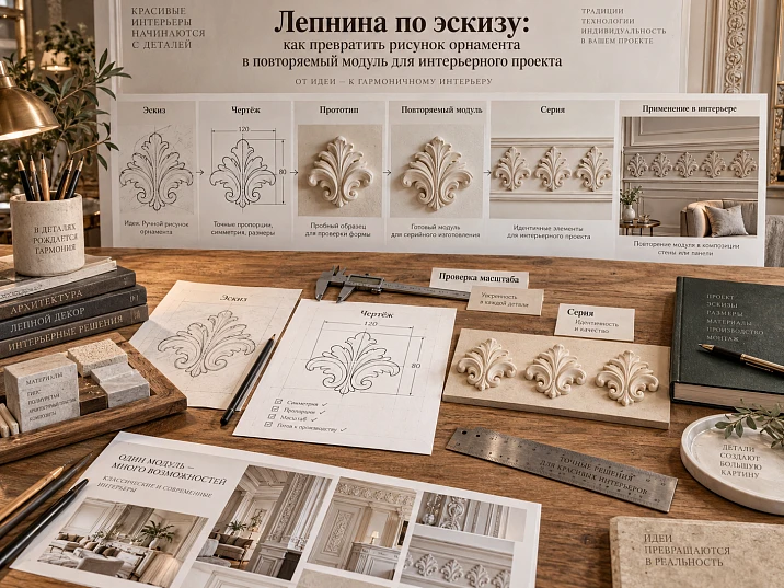
In the drawing, the branch flows smoothly above the door portal. But if you repeat it several times, a gap appears between the fragments, the leaves change direction, and near the corner the main scroll has to be trimmed. A single motif looks convincing — but a system has not yet emerged from it.
Stucco molding based on a sketch requires developing exactly such a system. It is necessary to determine the size and volume of the ornament, the repetition boundaries, the left and right versions, the transitions at the corners, and the endings of open lines. Otherwise, each subsequent section of the interior will require new manual adjustment.
For the designer, the task is to preserve the character of the pattern while translating it into reproducible parts. For the manufacturer, it is to obtain an unambiguous specification from which a sample can be prepared and a series approved. These tasks come together in specific dimensions, joints, and the approved version of the product.
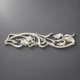
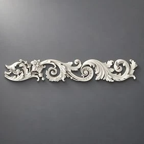
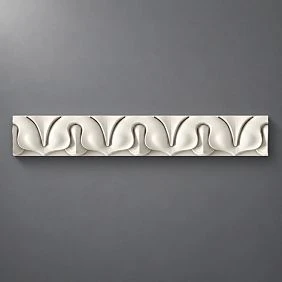
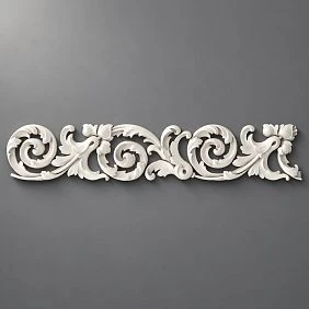
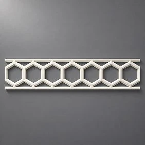
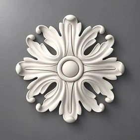
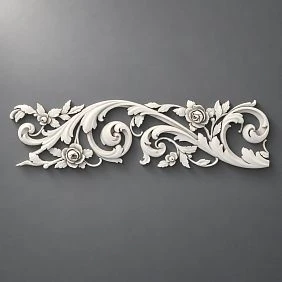
Check the ready catalog before developing a new ornament
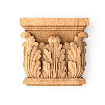
It is worth starting by comparing the sketch with existing products. In catalog of ready-made decor you may find a suitable overlay, rosette, linear profile, or elements for an assembled composition. They compare not only the style but also the scale, relief, orientation, and the possibility of joining the parts.
It is useful to write down exactly what the ready solution lacks. For example, the pattern is suitable, but its height exceeds the available field; the required right ending is missing; the motif does not continue in the required rhythm. Such a formulation turns the desire to “make your own” into a specific development task.
If the ready Polyurethane moldings satisfies these conditions, a new model need not be created. If only the central accent differs, one position may remain individual, while the surrounding profiles are taken from the catalog.
The comparison is carried out before manufacturing the sample and production tooling. At this stage, it is easier to change the composition of the solution. At the same time, a similar motif should not automatically be considered a replacement for the original: if specific lines, their position, and rhythm matter, the discrepancies are assessed together with the designer rather than hidden under a general ornament name.




Determine which elements the stucco molding should include according to the sketch
The drawing conveys the external appearance, but it does not yet describe the composition of the future set. A single standalone applique and a long repeating frieze may contain similar leaves, yet they require different borders and joints. Therefore, the roles of the parts are listed first.
| Element type | Task in the composition | What needs to be defined |
|---|---|---|
| Self-adhesive overlay | Form a complete motif | Contour, axis, and free field |
| Repeatable module | Continue the ornamental line | Repeat step and joint locations |
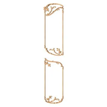
| Mirror pair | Decorate the left and right parts | Geometry of both sides |
| Corner element | Change the direction of the pattern | Type of corner and junction |
| Central element | Organize the composition around an axis | Scale and relationship with neighboring modules |
| ending | Complete the open line | End contour and transition from repeats |
One system may include several types, but it does not have to contain all of them. For example, a frieze between two portals will require repeatable details and endings, while a closed frame will also require corner solutions.
The composition is recorded on a general sketch of the wall or ceiling. This makes it clear where the same module is reused, and where a separate detail is hidden behind a similar pattern and cannot be included in the order under the same designation.
Our factory also produces:
Specify the overall dimensions and mounting plane
The first refinement of the sketch is the full-scale size. In the front view, the width and height are set by the extreme points, including protruding leaves and scrolls. If letter designations are used, they are explained on the drawing: the meaning of the letters may differ in different catalogs.
In addition to the outer rectangle, a mounting plane is needed. It shows which part of the product adjoins the base and from where the projection is measured. For a flat wall, a curved panel, and a corner section, these conditions differ. They cannot be reconstructed from a beautiful front view alone.
The sketch marks the boundaries of the available field and adjacent elements. For example, the ornament fits within the width, but its edge ends up too close to the architrave or extends into the door opening zone. Here, the overall dimensions of the part are checked together with its surroundings.
For manufacturing the decor according to the drawing, characteristic cross-sections and control points are also specified. All dimensions must refer to a specific state of the product: the model, the prepared part, or the finished surface, if this is essential for the fit. Acceptable deviations are discussed with the manufacturer for specific dimensions, rather than assigning a single arbitrary tolerance to the entire ornament.
Get Consultation
Separate the overall projection and the depth of the relief
The thickness of the product and the depth of its pattern are different characteristics. The overall projection is measured from the mounting plane to the outermost front point. The depth of the relief describes the difference between the chosen background and the protruding parts of the ornament. The same overall thickness does not guarantee the same character of light and shadow.
For example, part of the thickness may be occupied by a solid base, while the pattern above it remains low. In another variant, with the same projection, the background recedes deeper, and the leaves appear more voluminous. On a flat sketch, these variants can look almost identical.
Therefore, it is useful for the designer to designate the main planes: the background, the main branches, the front leaves, and the central accent. Then check whether the resulting shadows overlap the thin lines that defined the character of the original design.
The material and manufacturing method are agreed upon already at this stage. Thin protrusions, deep undercuts, and a complex back surface affect the reproducibility of the part and the design of the mold. The manufacturer evaluates them in relation to the chosen technology. A universal minimum sheet thickness or recess depth cannot be assigned based only on the appearance of the ornament on the screen.
Define the axis and the boundaries of acceptable asymmetry
For a central overlay, cartouche, or rosette, a clear placement axis is needed. It may coincide with the center of the overall bounding rectangle, but this is not a mandatory condition: a separate scroll can protrude farther than the others without changing the compositional center.
The drawing marks what should be symmetrical. Sometimes only the overall silhouette and the main branches are mirrored, while small leaves differ. If such a feature is not recorded, it may be accidentally removed during modeling or, conversely, an inaccuracy in the sketch may be mistaken for an intentional design decision.
For a repeatable system, the direction is also specified: top and bottom, movement of the motif from left to right, position of the face side. This helps avoid errors during assembly, when identical fragments are turned around and produce an unintended rhythm.
When selecting source motifs from polyurethane molding decoration the orientation is retained according to the card and drawing of the specific product. For a custom position, a separate scheme is introduced. In both cases, the axis must be reproducible: the installer needs a reference point, not a request to place a complex contour “approximately in the center.”
Find the repeat and separate it from the production module
A repeat is a repeating fragment of the pattern; its step determines the distance over which the ornament is reproduced along the line. The boundary is chosen so that the end of one repetition aligns with the beginning of the next. It does not have to pass through the most noticeable leaf or scroll.
The production module may contain one repeat, several repetitions, or designated joining sections. Its physical length and the pattern repetition step do not always coincide. This difference is especially important when counting parts and designing joints.
For example, if two full repeats are placed in one part, then for six pattern repeats, three such modules are needed with the accepted joining method. Ordering six parts will double the amount of material. The reverse error occurs when the module length is taken as the usable step without accounting for the overlap of adjacent parts.
On the drawing, the boundaries of the motif, the edge of the manufactured part, and its established length between the agreed joining boundaries are marked separately. These lines may coincide, but such coincidence is confirmed, not assumed. It is this marking that turns the ornamental sketch into a controllable repetition system.
Check several repeats next to each other
A single module can hide the problem of its own edge. Therefore, at an early stage, the pattern is repeated in at least several adjacent positions and viewed as a continuous strip. Not only the joint contour matters: the distance between large motifs must preserve the intended rhythm.
At the boundary, check the direction of the branch, the height of its exit, the position of the leaves, and the thickness of the visible line. If the stem rises at the end of a module and the beginning of the next one is positioned lower, formally identical parts create a noticeable jump. It is better to eliminate this in the geometry than to mask it during finishing.
Then the connection is checked in three dimensions. A matching frontal contour may hide a difference in protrusion or a sharp change in surface slope. Under side lighting, such an area reveals the joint even without a visible gap.
Before the series, it is useful to assemble a trial sequence from real parts. It shows the result of production and the chosen joining method, which simple image copying does not provide. The joint markings are kept in the documentation: the installer must understand where to connect the elements and which surfaces form the transition, without having to determine the position of each fragment anew.
Left and right versions receive separate designations
Mirroring the pattern in the program and rotating the finished part are different operations. With a directional ornament, flipping can swap top and bottom, disrupt the position of the leaves, or lead to incorrect mating with the adjacent element. Turning the part back side out also cannot be considered a replacement for mirrored geometry.
The need for a pair is determined by the overall composition. If the branches diverge from the center, the left and right sections may require different products, even with identical dimensions. If the motif allows one part to be used in both positions, this is confirmed on the assembly diagram.
For custom development, conditional codes “Ornament-01-L” and “Ornament-01-R” can be introduced. They designate two positions, not two ways of naming one. On the drawing, the front view, top, and installation side are labeled. The letter designations L and R in the finished catalog are also retained as part of the full article number.
The quantity of each side is counted separately. The entry “24 paired elements” is ambiguous: it could mean 12 pairs or 24 pairs. It is more reliable to specify 12 left and 12 right parts if that is exactly the composition required by the approved layout.
The corner module is developed for a specific rotation
A flat ornament cannot be automatically turned into a corner one by simply rotating the image. It is necessary to determine what changes: the direction of the line on one wall, the transition to the adjacent wall, or wrapping around a protrusion. These situations require different spatial geometry.
With a flat frame, the transition of the motif from the horizontal section to the vertical one is important. At an inner or outer corner of the room, two mounting planes are added. On the model, not only the face pattern is checked, but also how the part sits on the base.
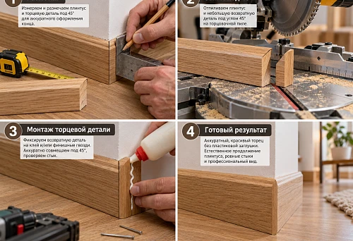
Even at a right angle, an accurate cut by itself does not guarantee a successful match of the ornament. At the joint line, two cut leaves or overly dense scrolls may meet. In a custom system, the corner makes it possible to organize this transition in advance, if such a solution is justified by the project.
When choosing a ready-made decoration for moldings the purpose of the element and the associated profile are specified. For a custom corner, the directions of the joints and the position of the pattern on each side are additionally set. The test assembly is put together with the straight modules: separately from them, the corner piece does not confirm the continuity of the entire line.
Design the endings of an open ornament
A repeating pattern has no natural end unless one is specifically chosen. If a strip is cut to the required length without checking, the line may end with half a leaf or a broken stem. That is why the edge of the composition is developed together with the main repeat.
Different solutions are possible: ending on a calm section of the pattern, a separate finishing piece, a gradual reduction of the motif, or a transition into an adjacent architectural element. The choice depends on whether the edge should remain neutral or become a noticeable accent.
For the left and right ends, the direction of the ornament is checked. Endings that are identical in size may have different shapes. Their established length is taken into account when calculating the strip, and the overlap with the main module must not be counted again in the overall dimension.
The ending is evaluated on the full wall fragment: near the architrave, niche, or adjacent frame. Sometimes a separate piece looks proportionate, but in the project field it almost runs into the boundary. Then the length of the repeating part or the ending itself is adjusted before the series is manufactured. Trimming an already approved ornament on site must be provided for by the pattern and the working documentation.
The central motif gets its own geometry
The center of the composition may stand out by size, direction of the branches, or density of the pattern. But simply enlarging the repeating fragment changes several parameters at once: the thickness of the stems, the depth, and the distances between the details. As a result, the accent sometimes no longer belongs to the same system.
The central element is best checked together with the adjacent modules. Characteristic lines and the scale of small details are preserved where continuity is needed, while the enhancement of expressiveness is created deliberately. Its own axis becomes the starting point for the layout to the right and to the left.
If the pattern must diverge in a mirror image, the two transitions from the center are checked separately. Compatibility of one edge does not prove compatibility of the other. A large cartouche or rosette may require different connecting sections despite the overall symmetry of the outer contour.
The central detail is assigned a separate code and dimensions. It occupies part of the composition's length, so it cannot be added on top of an already calculated number of repeats without recalculation. For wall decor made of polyurethane such a check is especially useful above portals and in extended panels, where the center axis must align with the architectural reference.
Combine custom ornament with ready-made products
An individual composition does not necessarily require developing every profile from scratch. Ready-made Moldings made of polyurethane can form a frame, while a custom overlay serves as the central motif. In this case, the development is focused on the detail that truly distinguishes the project.
The connection is checked against the actual cross-section of the selected molding. You need to know its mounting plane, projection, and the position of the junction area. The custom ornament must not accidentally overlap the profile's track or leave an unprepared transition in depth.
Similarly, you can use a ready-made ceiling outlet with individual diverging elements. Their scale is evaluated together with the entire rosette, not just with a single leaf of its pattern. The overall diameter of the composition and the free field around it are checked.
The task includes the full product code and the dimensional specification of the finished part. If it changes, the interface is reviewed. The wording "for a standard moulding" is insufficient: similar products differ in cross-section and projection. A mixed solution reduces the scope of custom development only when the finished and bespoke parts are coordinated as a single set.
Approve the model and dimensional drawings
For complex relief, a 3D model helps verify overlapping leaves, depth variations and joint surfaces. Dimensional drawings show reference dimensions, axes and datums in a format convenient for approval. Both representations must describe the same geometry.
| Development material | Main task | What to verify before approval |
|---|---|---|
| Sketch | Convey the character of the pattern | Motif, direction, desired symmetry |
| 3D model | Describe the volume and surfaces | Scale, relief, back side and joints |
| Dimensional drawing | Lock the controlled geometry | Dimensions, axes, sections and units of measurement |
| Layout diagram | Show the application of parts | Sequence, sides and extreme points |
The file format alone does not guarantee accuracy. A 3D model must also have the correct dimensions, and a DWG drawing may not contain enough data to reproduce a complex surface. The required formats and scope of delivery are agreed with the manufacturer.
For finished parts, use catalogs, drawings and models of stucco moldings, checking the selected version. Individual files are linked to the development code. If the model and the drawing diverge, the contradiction is resolved before manufacturing the sample, rather than asking the contractor to choose the more convenient version.
Separate the master model from the series reference sample
A prototype allows the developed shape to be seen physically. In mold making, the master model serves as the original for producing the mold. The reference sample confirms the result of manufacturing the part itself. These roles may be related, but they must not be conflated during approval.
For example, a printed prototype shows the scale and relief, but it does not confirm the surface of a product made from another material. Approval of such a prototype means agreement on the verified properties, not automatic acceptance of a future batch on all characteristics.
The development sequence is discussed in advance: which decisions are approved on the model, when the physical original appears, and at what stage the manufactured part is checked. For a complex ornament, a sample joining several elements is useful, since a separate fragment does not show the accumulation of deviations and the nature of the repeats.
Before the series is released, a control sample and the documentation of one version are approved. Changing the shape after the tooling has been manufactured may require reworking or replacing it, so disputed leaves, corners, and junctions are better checked earlier. At the same time, the specific technological sequence is determined by production: an article or sketch does not replace an assessment of the feasibility of manufacturing the chosen relief.
Check the finish and record the characteristics of the approved sample
A color card does not show how the coating will settle into the recesses and change the readability of thin lines. A test coat is applied on the actual relief with the agreed surface preparation. For patination, it is especially important to see which areas of the design become darker and whether neighboring details merge.
The sample is examined under the lighting specified by the project and from a normal distance. A small scroll that is expressive up close may disappear from the overall design after painting. If this changes the composition, the finish or geometry is adjusted before final approval.
| Group of characteristics | What the control sample confirms |
|---|---|
| Shape | Silhouette, relief plans, and preservation of small details |
| Geometry | Agreed dimensions, mounting surface, and junctions |
| Repetition | Nature of the transition between adjacent modules |
| Finishing | Preparation, specific finish, color, and gloss level |
Permissible deviations and the verification method are recorded separately: a sample does not replace numerical requirements where they are needed. Catalog Product samples help to preliminarily evaluate the material and finished products, but they are not the reference standard for an author's ornament that has not yet been developed. For it, a separate approved set with a date and version is maintained.
Assign a code to each geometry and assemble the package for production
One designation must lead to one unambiguously defined part. A repeating module, a left end, and a center receive different codes. If the geometry changes, a new version appears; if two executions are needed simultaneously, they must not be hidden under one name.
For example, the conditional position "Ornament-01-L, version 02" must have a coordinated model, drawing, and sample of exactly this version. Old materials are kept in the archive with a clear note so that production does not receive an outdated file from a previous email.
The package includes the project name and installation zone, element type, dimensions, axes, material, requirements for the back surface and finish. For a repeating ornament, the pattern pitch, the established module length, and the connection scheme are added. For paired parts — the side and quantity of each execution.
The general sketch is kept together with the technical files: it explains the purpose of the parts. But the launch of manufacturing decorative elements is tied to the approved version of the specification, not to the latest picture in the correspondence. When one element is changed, dependent positions are checked. A new shape of the center, for example, may require reworking the joints of both adjacent modules.
Count the modules after subtracting the center and the ends
The quantity depends on the established length of the parts and the layout, not only on the wall footage. Let us consider a conditional line 3240 mm long: the ends take 60 mm each, the central element — 240 mm. Here all values mean the contribution to the finished length, without double-counting overlaps.
The repeatable sections account for 3240 − 120 − 240 = 2880 mm, i.e. 1440 mm on each side. The pattern repeat is 240 mm, and one module contains two repeats and occupies 480 mm. Therefore, three modules are required on the left and three on the right — six for the entire line.
In this example, the pattern allows one type of repeatable element on both sides. For four identical lines, the composition will be as follows:
| Position | Per line | For four lines |
|---|---|---|
| Repeatable module | 6 pcs. | 24 pcs. |
| Left end | 1 pc. | 4 pcs. |
| Right end | 1 pc. | 4 pcs. |
| Central element | 1 pc. | 4 pcs. |
If the main pattern requires mirrored modules, they are also divided into two positions. If the remainder is not a multiple, the length, edge sections, or system composition are revised. Simply rounding the quantity up does not resolve where to cut the ornament. The reserve is calculated based on specific elements, taking into account the adopted technology, rather than assigning a universal percentage to the entire set.
How to order stucco work from a sketch and preserve the possibility of repetition
For an initial inquiry, prepare a drawing, the estimated dimensions, material, application scheme, and planned quantity. This is sufficient to discuss the scope of development and any missing data in a substantive way. The production package is supplemented based on the results of approval; a finished sketch does not yet mean a finished series.
Opening unique opportunities for home craftsmen to express creativity and create unique architectural compositions. This process requires patience, precision, and deep understanding of technological features, but rewards the creator with pride in the completed work and significant savings on the family budget. production of decor based on a designer's project are discussed in relation to the specific geometry and production run. STAVROS states that accepts custom items for production in a run of. Development conditions, permissible order volume, sample preparation, and timelines are clarified through STAVROS contacts, without assuming identical conditions for all ornaments.
If a suitable catalog set is found, you can order ready-made items and keep only the missing part custom. If fully bespoke molding is required, the geometry, junctions, and a control sample are approved before the series.
For repeat orders, codes, file versions, material, finish, and the approved reference sample are retained. Storage of production tooling and the conditions for its reuse are agreed separately. Then, after some time, you can return to a specific system of parts, check its relevance, and order a continuation of the ornament without trying to reconstruct the entire project from a photo of the finished wall.