








































































Article Contents:
- First, determine how the recessed field is constructed
- Set the front plane of the frame as the zero level
- If the offset varies along the perimeter
- The section shows the contact, not just the silhouette
- The width and height of the molding are not equal to the dimensions of its support
- Three positions of the profile relative to the panel
- If the profile lies entirely on the frame
- If the profile is installed on the panel itself
- What happens when the molding crosses a level change
- The rebate on the back side is checked as a separate fit
- Glue does not replace a geometry decision
- The intended freedom of movement is preserved for a movable panel
- For a glass insert, check the separate retention assembly
- The inner contour is calculated based on the actual profile overlap
- Check the handle together with the new relief
- The central decor is placed after determining the free field
- A full-size template helps before purchasing a batch
- A physical sample verifies the actual joint
- Assemble one control facade before the series
- The finish must not hide an unresolved installation issue
- The working drawing must define the profile position
- The specification links the product and the installation solution
- When it is wiser to change the profile or its position
- Where to buy a wooden profile for furniture
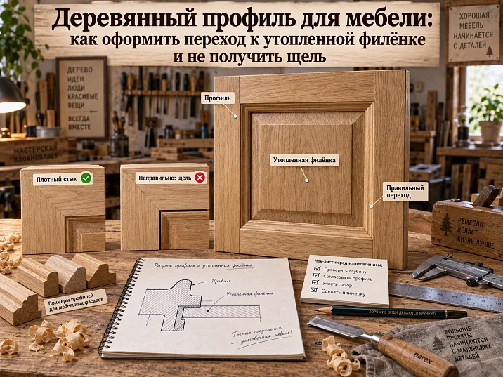
On the front sketch, the molding neatly frames the panel. During a test fit, a different picture emerges: the outer part of the strip rests on the facade frame, while the inner part hangs over the recessed insert. If you press the inner edge down, the outer edge lifts. Adding glue seems like the quickest solution, but first you need to understand what the profile should actually be supported by.
A wooden profile for furniture on such a facade is selected and installed based on the cross-section of the assembly. It shows the face plane of the frame, the depth of the central field, the actual mounting surface of the molding, and its position relative to the step. The front view defines the composition's pattern; the section defines whether it can be assembled.
At the same time, the profile protruding above the panel is not always a mistake. It may be intended by the design. A mistake occurs when the support, fastening, and clearance under the protrusion have not been checked, and a beautiful line on the sketch is taken as a ready-made installation solution.
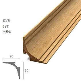
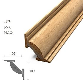
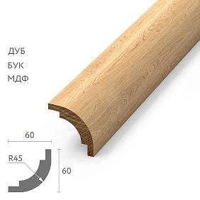
First, determine how the recessed field is constructed
Similar appearances can conceal different bases. In one front, the recess is milled into a solid panel. In another, a separate panel sits inside a wooden frame. In a third, glass is installed with its own fastening.
For a decorative profile, these are different conditions. In a solid piece, both planes belong to the same base. In a framed front, the central insert may have intentional movement. With glass, you need to consider how it is held, whether it can be replaced, and whether contact with additional decor is acceptable.
Before choosing where to glue, find a cross-section of the front or inspect the actual construction. Confirm the insert material, thickness, installation method, and the purpose of the existing gaps.
Do not assume that any recessed panel is rigidly connected to the frame. Decorative modification must preserve the front's intended movement.




Set the front face of the frame as the zero level
In a working drawing, it is convenient to take the main surface of the frame as 0. The surface of a flat recessed insert will be lower, for example at −6 mm. The difference itself is then 6 mm.
This is a conventional example for explanation, not a recommended panel depth. For a specific product, measure the actual distance between the relevant surfaces.
For measurement, use a flat base resting on the main plane and a suitable depth gauge. Check several places around the perimeter. A protruding bead, chamfer, or bevel on the frame must not accidentally become the measuring base instead of the surface on which the molding will sit.
If the panel has its own relief, a single dimension to its center is not enough. For the profile, the depth in the area of the intended joint is what matters. It may differ from the depth of the central flat area.
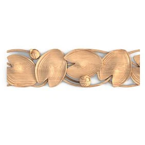
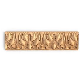
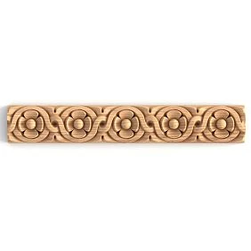
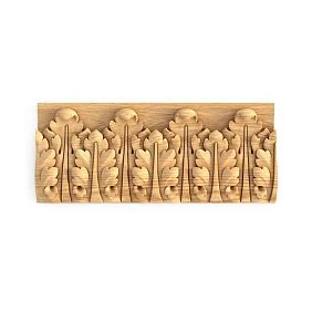
Our factory also produces:
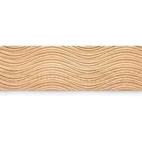
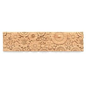
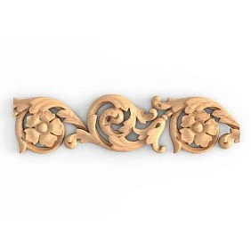
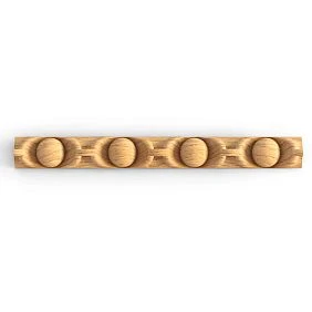
If the difference varies around the perimeter
Suppose 6 mm is measured at one edge and 8 mm at the other. The average value of 7 mm does not describe either of these areas accurately enough for checking fit. On the diagram, keep both results and their positions.
Determine the cause of the difference: the intended shape of the insert, the position of the parts during assembly, or a deviation of the base. Compare the result with the project requirements. The difference alone does not yet provide grounds either to accept the facade or to declare it unsuitable.
Apply the profile sample at the areas that differ most. If the position fits on only one side, it is too early to run the entire set based on the single successful section. First, confirm the geometry of the base or refine the transition design. Otherwise, during assembly, identical strips will press differently, and the junction line will depend on the clamping force.
Get Consultation
The section shows contact, not just the silhouette
Draw the frame, the insert, and the selected profile section at the same scale. Separately mark the area that actually contacts the base and the area beneath which a gap remains.
A conventional frame around the panel in the front view does not show this difference. Two identical rectangles may correspond to completely different assemblies: the profile is either fully glued to the top surface or partially overlaps a step.
The documentation for the selected model can be found in the section drawings and models STAVROS. But the product drawing must be combined with the facade drawing. On its own, it does not yet confirm that the mounting surface will land on the correct base.
To begin with, a section through a straight run is sufficient. Before manufacturing, additionally check the corners and the places where the profile meets other parts.
The width and height of the molding are not equal to the dimensions of its support
The width shows how much space the profile occupies in the projection onto the facade. The section height describes the protrusion of the relief relative to the accepted base. The actual rear support may be narrower than the overall width or may consist of separate sections.
For example, in the product page of the MLD-014 moulding a section of 25 × 20 mm is specified; versions in beech and oak are offered at a length of 2400 mm. These figures allow you to determine the product configuration, but they do not prove that the model will cover a specific ledge on your facade.
The 20 mm height cannot automatically be taken as the seating depth or as compensation for an uneven surface. To do this, you need to know the shape of the back side and the chosen orientation.
On the section, separately mark the overall dimensions of the profile, its mounting surface, and the width of the actual contact. Then the choice no longer depends on how well the molding looks in the photograph.
Three positions of the profile relative to the panel
The main options are convenient to compare before cutting.
| Position | Where the mounting support is located | What needs to be confirmed |
|---|---|---|
| Entirely on the frame | On the main plane of the facade | Sufficiency of a flat area and the position of the inner edge |
| Fully on the insert | On a recessed surface | Permissibility of fastening to the insert, its strength and performance as part of the facade |
| Crossing a level difference | On the selected support area or on a specially prepared base | The design of the rear side, the fastening, the amount of protrusion and the required gap |
The third option requires a detailed section. It cannot be accepted merely because the visible width of the molding fits between adjacent elements.
Full support of the entire rear surface is not the only possible construction. However, the provided protrusion must have justified fastening and must not interfere with the insert. There is no universal permissible ratio of the supporting and protruding parts.
If the profile lies fully on the frame
Check the actual width of the flat area. The visible frame strip may include a bevel near the panel that cannot be considered a continuation of the flat mounting surface.
Set the molding position from a clear edge or axis. Specify the distance to the start of the step, not just the offset from the outer edge of the door. Then the change in frame width will be visible in the drawing.
In this option, the profile can be brought closer to the panel while keeping its mounting support on the frame. However, the visual transition may differ from the original sketch: an open strip will remain between the relief and the recessed field.
Evaluate it before finishing. Sometimes such a gap makes the composition calmer, sometimes it requires a different section. Adjusting the position only for a beautiful frontal contour while losing support is not worth it.
If the profile is installed on the panel itself
First confirm that the insert allows such modification. A thin panel, a floating solid wood panel, and glass should not receive the same solution out of habit.
A profile fixed to a movable insert becomes part of its own assembly. It must not simultaneously press against the fixed frame in a way that blocks the intended movement.
The height of the relief relative to the facade will also change. In the conditional example, the mounting surface is at −6 mm. If the maximum profile height from this surface is 12 mm, its top point will be at +6 mm relative to the frame. The same profile installed on the zero plane would protrude by 12 mm.
The calculation applies to the specified simple geometry and the accepted measurement base. For a complex rear shape, the position is checked against the actual section.
What happens when the molding crosses a step
Let us imagine a profile with a flat rear surface 30 mm wide. According to the design layout, 18 mm rest on the frame, while the remaining 12 mm extend over the recessed field. The panel is positioned 6 mm below the frame.
In this position, a 6 mm high space remains under the inner part of the flat back. The presence of a total width of 30 mm does not turn it into an adhesive contact.
| Parameter of the conditional example | Value | What follows from it |
|---|---|---|
| Width of the flat back | 30 мм | Overall transverse contact dimension on a level base |
| Part above the frame | 18 мм | This is exactly where the support is located in the example |
| Overlap over the panel | 12 мм | This section overlaps a lower surface |
| Drop | 6 мм | The corresponding space remains under the protruding part |
These figures are not tolerances or a recommendation for fastening. The sufficiency of support is assessed for a specific profile, substrate and installation method. The percentage of overlapped width alone does not confirm the reliability of the joint.
The step on the reverse side is checked as a separate fit
A profile with a rebate or stepped back may fit the level difference geometrically better than a flat strip. But the depth of the step, the width of the bearing areas and the position of the boundary between the two levels must all match.
Also check radii and chamfers: a sharp corner of the substrate may hit the profile's rounding before its mounting surface reaches its intended position. Such an obstruction is not visible from the overall bounding rectangle.
If the profile needs to be modified, confirm the remaining cross-section and the fastening method after modification. The mere fact that the rebate depth matches the level difference does not make the joint ready for installation. On a movable insert, the intended movement of the joint is still preserved; tight contact between the two levels does not mean they may be glued together.
Adhesive does not replace a geometry decision
A thick random bead of adhesive under the overhanging edge does not justify considering the joint verified. The permissible layer thickness, surfaces and curing conditions depend on the chosen compound.
There is another problem too: filling the space between the frame and the panel can create a connection where the design requires the parts to work separately.
If the support is insufficient, consider changing the position of the moulding, using a different profile, an intended shim, or reworking the substrate. Each modification must have its own detail drawing. The shim must also not accidentally connect the fixed frame to the movable insert.
В Titebond's explanations it is separately noted that most woodworking glues of this brand are intended for unfinished wood; when bonding through paint, the result also depends on its adhesion to the substrate. Therefore, the contact geometry and surface condition are checked together.
The movable panel retains its intended freedom
In a traditional frame-and-panel construction, the central solid wood component can change dimensions within the grooves. This principle is described, for example, in the chapter on solid wood furniture construction by Christian BecksvoortDecorative molding must not accidentally block this operation.
If it is attached to the frame and overlaps the edge of the panel, the design specifies where free space is preserved and which surfaces are not glued to each other. You must not fill the entire visible joint just to avoid a dark line.
The required gap is determined by the construction, dimensions, and material. The promise that "two millimeters is always enough" does not apply here.
An intended gap and an accidental crack serve different purposes. The first ensures the assembly functions; the second appears due to mismatched parts. Before making corrections, you need to determine what exactly you are seeing on the facade.
For a glass insert, check the separate retention assembly
The profile near the glass may serve a decorative function or be part of a retaining assembly. These roles must be specified in the design.
The presence of a wooden strip around the perimeter does not yet make it a suitable glazing bead. You need to know what holds the glass, where the support areas are located, and how the insert can be replaced. Do not add an arbitrary rigid edge clamp just to close a visible gap.
If the molding blocks access to the fastening, check the assembly and disassembly sequence before installation. For a display case or cabinet door, this is a practical matter: decorative refinement should not turn a routine insert replacement into destruction of the facade.
The glass fastening technology and the compatibility of contacting materials are taken from the design of the relevant assembly. Recommendations for gluing wood to wood do not automatically transfer to glass.
The inner contour is calculated based on the actual overlap of the profile
The visible central field is reduced by the part of the molding that overlaps it in the front projection. This is not necessarily the full width of the profile.
Let us continue the conditional example. Before installing the molding, the open rectangular field measures 380 × 620 mm. If the profile overlaps it by 12 mm on each side, the visible opening will become:
380 − 2 × 12 = 356 mm; 620 − 2 × 12 = 596 mm.
Subtracting the full 30 mm width from the field on each side would be a mistake: part of the profile lies beyond its boundary, on the frame.
This calculation describes the visible area. The size of the panel itself, including the hidden parts in the grooves, is determined separately. For a relief field and a non-rectangular contour, the dimensions are checked against the actual geometry.
The handle is checked together with the new relief
After changing the inner contour, the previous handle position may become inconvenient. The profile approaches the grip point, protrudes under the fingers, or crosses the mounting location.
On the control facade, place the actual handle and check the hand movement. The front view shows the distance between silhouettes but does not explain whether there is enough space behind the handle.
Clarify which part the fastener passes through and where the opening force is perceived. You cannot move the handle from the frame to a thin insert just because it fits better inside the molding.
For a molding on a furniture facade, the outer protrusion also matters. Check the door opening next to an adjacent facade, wall, or other overlay part. A comfortable position on a closed door does not confirm the absence of collisions in motion.
The central decor is placed after determining the free field
If the panel provides carved appliqués or Wooden sockets, first determine the field boundaries after installing the profile. Then try the decor in the remaining area.
In the example with an opening of 356 × 596 mm, the central overlay should be evaluated within these boundaries. Additionally, its height, shadows, and proximity to the handle are taken into account; a width check alone is not enough.
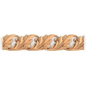
If used carved decor for moldingscheck its own rear surface. A surface-mounted connector can also cross the step and may need its own support.
Decor that simultaneously touches the frame and the movable insert cannot be considered harmless just because of its small area. Its fastening is checked using the same scheme as the profile fastening.
A full-size template helps before purchasing a batch
Transfer the cross-section onto dense cardboard at a 1:1 scale. Mark the zero surface, the field depth, the mounting side and the step boundary. Verify the print scale with a control dimension.
Place the template against the actual facade or its verified mock-up. It helps you quickly see where the rear surface lands, how far the relief protrudes and how the inner contour changes.
But cardboard does not show the exact fit, the condition of the wood or the behavior of the adhesive joint. It also does not confirm that the narrow support zone is sufficient.
After checking the scheme, use a physical sample. If the profile is to be modified, the sample must show exactly that modification, not just the original stock cross-section.
A physical sample verifies the actual junction
in the STAVROS catalog Samples of linear products 100 mm long. The material of the specific sample is specified: the section offers MDF, beech and oak.
For comparing shapes, you can use Molding samples set OMLD-005But choosing a similar silhouette does not yet confirm its suitability for the level difference of your facade.
Place the sample on the selected mounting base without final fixing. Check where it actually touches the base and what is under the protruding part. Do not press the inner edge down by hand, hiding its original position.
A short sample shows a local cross-section. For the long side, corners and the entire frame, a full trial fitting will be required after this.
Assemble one control facade before the series
Check the selected profile on the actual product: a dry layout of the four sides, the fit on straight sections and in corners, the inner field, the handle and opening.
Inspect the level difference along the entire perimeter. On one side of the frame the support may be sufficient, while near a corner it may decrease due to a bevel or another decorative element.
for decorative solid wood strip with simple geometry, this stage is also necessary. A rectangular cross-section does not eliminate the difference between base levels.
After confirming the geometry, perform the specified trial finishing and check the finished assembly. The facade becomes a control one only after the result is accepted as a whole, and not after a successful fitting of one short sample.
The check must result in five things being accepted: the support zone, the free inner contour, the operation of the insert, access to the handle and the installation sequence. If at least one question remains open, note it in the task before transferring the facade to the series. This is more accurate than a general conclusion that “the molding fits”.
Finishing must not hide an unresolved installation issue
The oak profile, frame and panel can have different grain directions. Under tinting or a clear finish, evaluate them together. A test color on a single flat board does not show the whole composition.
Beech under a covering enamel reduces the significance of the natural shade but leaves the transition geometry and the abutment line visible. If the profile rocks on a step, painting will not give it support.
In the description quality of STAVROS wooden products blanks for enamel and for tinting differ. The required version is chosen together with the finish, while keeping a separate check of the installation geometry.
In the working procedure, specify which surfaces are finished before assembly, which after, and where a prepared adhesive contact is required. The designated movable joints must also retain their purpose after coating.
The working drawing must specify the position of the profile
The note “molding around the perimeter” is too vague for a facade with a step. The installer needs a base and an installation coordinate.
On the section, indicate the main plane 0, the position of the insert, the cross-section of the selected model and the distance from the defined edge to the profile. Separately show the support zone, the designated projection and the areas that must not be glued to each other.
On the front view, indicate the inner contour, the handle and the central decor. If the profile position differs on the horizontal and vertical parts, this must be shown explicitly.
Two facades with the same molding may require different coordinates: their frame width, field depth or handle location differ. Copying the article number does not replace transferring the entire verified assembly.
In the specification, the product and the installation solution are linked
A repeat order requires the product configuration, while repeat assembly requires a link to its installation drawing. Keep both types of information.
| Field | What to record |
|---|---|
| Profile | Article number and link to the card |
| Size and material | Cross-section, commercial length, beech or oak |
| Preparation | Selected blank version |
| Product | Facade number and position of each side |
| Mounting base | Frame, insert or provided base |
| Deviation and coordinate | Dimensions per working cut |
| Mounting | Confirmed method and contact areas |
| Finishing | Technology code and control sample |
| Documentation | Drawing number and its current revision |
If the panel depth, insert material or profile changes, the assembly is re-checked. The old control facade remains confirmation only of the previous configuration.
When it is more sensible to change the profile or its position
Go back to the selection if the mounting support is not confirmed, the relief covers the central field excessively, interferes with the handle, or requires blocking the movable insert.
Possible solutions are to shift the profile onto the frame, reduce the inward overlap, choose a different cross-section, or rework the base. When choosing a new model, repeat the section check and the physical fitting.
Not every molding you like can be applied to an already finished facade without changing the project. If it requires simultaneously reworking the panel, the handle fastening and the finishing scheme, compare the scope of modifications with replacing the profile itself.
Buy Pogonazh iz massiva for the series comes after such a comparison. Matching the style is important, but it does not confirm the compatibility of mounting surfaces.
Where to buy a wooden profile for furniture
Select Wooden profile for furniture in the STAVROS catalog is more convenient using a prepared facade section. Record the offset, the width of the available support, the required inner contour and the maximum protrusion specified by your project.
If you need to buy wooden moldings for furniture in a small series, start with a suitable configuration and a sample. Before ordering the entire batch, confirm one facade, including fastening and finishing.
В installation and finishing tips different states of the surfaces being joined are taken into account. When selecting Mounting and finishing materialscheck their applicability to your substrate and the adopted construction.
For regular purchasing, review conditions for manufacturers, and before placing an order — payment and delivery. Availability of versions and additional work are confirmed for each specific order.
The profile is handed over for installation together with a clear installation rule: where its support is, how far it extends over the panel, and what gap must be maintained. Then the transition line is provided for by the design, rather than determined by the random thickness of glue during assembly.