Article Contents:
- First, draw the entire path
- Check the profile at the most complex point
- Inner corner: preserve the orientation of the section
- Consider the outer corner from two directions
- A ready-made decorative corner is suitable for a specific junction
- Keep left and right parts separate
- Returning the profile to the wall closes the termination
- When a straight termination is acceptable
- Four solutions near the door casing
- Compare the projection of the molding and casing from the common plane
- Near built-in furniture, check the movement of the fronts
- A niche requires choosing a route
- Arch: check the shape, direction of curvature, and execution
- Transition from straight molding to flexible
- Around a column and at the boundary of zones, the line may break
- How to bring a vertical to the ceiling cornice
- The ornament must be aligned on both sides of the turn
- What to show on the drawing of a complex junction
- A three-dimensional model verifies how the junction is perceived
- A trial assembly is needed for repeating terminations
- After the junctions, compile a list of parts and place the order
- Mistakes worth checking before purchasing
- Where to order architectural mouldings for ready-made junctions
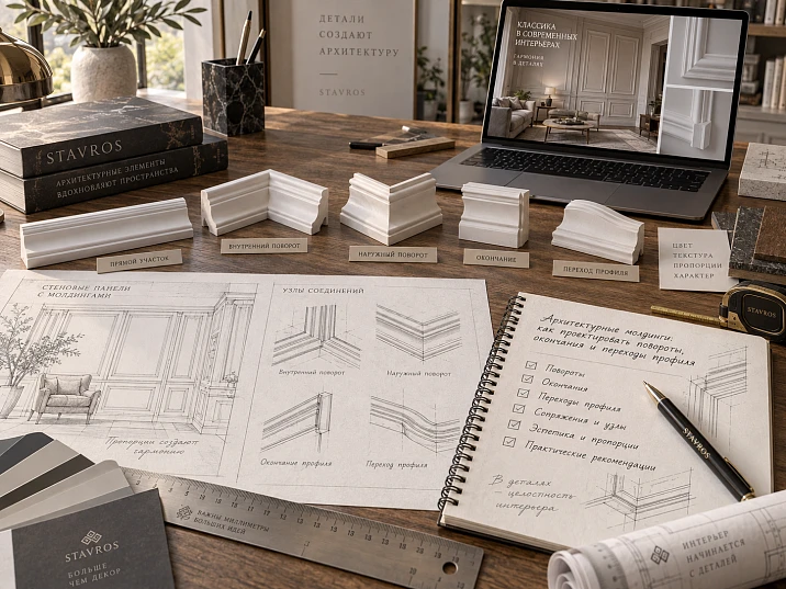
A horizontal moulding reaches the door casing but protrudes in front of it. On the elevation, the two lines met neatly; when viewed from the side, an open end appeared. What has to be corrected is no longer the wall drawing but the specific junction: change the profile, move the termination back, or return to the wall.
Architectural mouldings are chosen together with the trajectory and the method of termination. Before ordering, you need to determine where the line begins, how it passes through corners and openings, what happens near furniture, and where the profile ends. After that, the cross-section of the actual product is checked and junctions are produced for complex locations.
First, draw the entire trajectory
On the elevation, draw the line of the future moulding and mark its start, end, turns, intersections, and areas where the plane changes. For now, a conventional line without decorative relief is sufficient. It shows the architectural intent; the profile chosen later must confirm its feasibility.
For each special point, record the solution: internal corner, external corner, junction with the casing, return to the wall, standalone termination, or transition to an arch. Assign designations to repeating junctions, for example J-01 and J-02. The same shape on different walls may require different solutions if a door and a fixed panel are nearby.
Check the trajectory from both ends. It is not uncommon for the line to start convincingly from the portal but end in a short random fragment near the cabinet. It is better to change such a spot before choosing the product.




Check the profile at the most difficult spot
A long straight section rarely tests all the requirements for the molding. The outer corner, a short end, or a transition to an arch is far more revealing. If the profile does not pass this junction, its expressiveness on a free wall does not solve the problem.
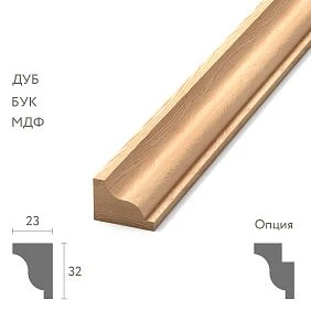
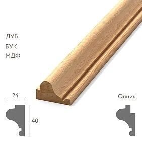
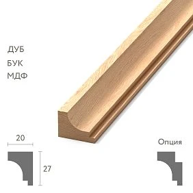
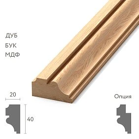
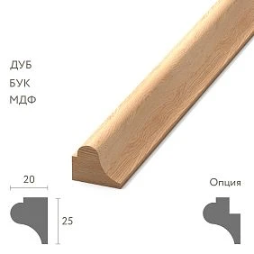
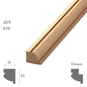
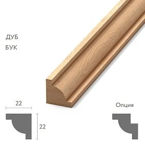
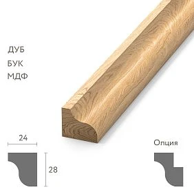
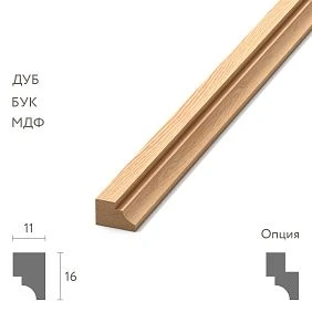
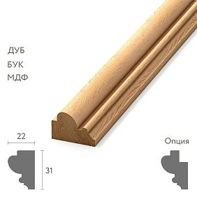
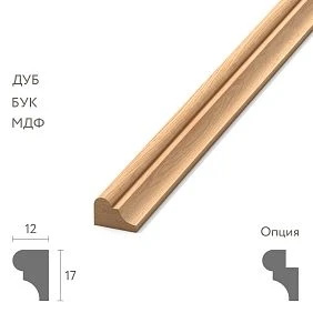
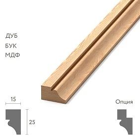
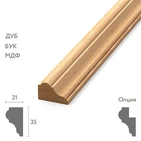
You need width A, depth C, the full cross-section, and the mounting plane. For an asymmetric profile, mark the top, bottom, and the side facing into the frame. Simply rotating the image does not always preserve the required arrangement of beads and grooves.
For example, molding MLDPU-003 has a size of 35 × 12 × 2600 mm. In the frame it occupies a strip 35 mm wide, and when adjoining a neighboring part, the 12 mm depth must also be checked. None of these numbers on its own describes the method of termination.
Our factory also produces:
Inner corner: preserve the orientation of the cross-section
First distinguish between two cases: rotating the frame on a flat wall and transitioning the profile from one wall to another. In a frontal drawing they may look similar, but the cut planes and the position of the product during processing differ.
For a right angle and the corresponding joint scheme for identical profiles, paired 45° cuts are used. The actual angle between the walls is checked beforehand: nominal 90° on the plan does not guarantee the same geometry of the base. If there is a deviation, the junction is refined and a trial fit is performed.
At the inner joint, the characteristic relief lines must match. If on one side a large bead ends up higher and on the other lower, filling the seam will not correct the wrong orientation. For an ornamental profile, the pattern on both sides of the turn is additionally checked.
Get Consultation
Examine the outer corner from two directions
The outer corner opens when moving along both walls. Here, not only the joint line is noticeable, but also the protruding part of the profile, the thickness of the edges, and the change in shadow. Pay especially close attention to deep molding on a narrow protrusion or near a passage.
Show the assembly in plan, then look at it from both sides. Make sure the turn preserves the cross-section and does not create an unintended protrusion. If the corner is hidden by furniture in one direction, this does not mean it is not visible from the other.
Do not rely on a thick layer of finishing compound to correct the geometry. First, the parts themselves must fit together; materials for joining and finishing are selected according to the requirements of the specific product and substrate.
A ready-made decorative corner is suitable for a specific assembly
Polyurethane corner moldings and separate corner elements solve different tasks. A shaped piece for a frame on a single plane does not become a ready-made outer corner between walls just because of its name.
In the section decoration for moldings select products associated with a specific profile. For example, MLDPU-003U measuring 218 × 218 × 15 mm is intended for a shaped turn of the molding line; the description states compatibility with MLDPU-003.
Such an element changes the dimensions and character of the frame corner. On the drawing, it must be placed in full, the junction points with straight sections must be determined, and the distances to the door or furniture must be checked. The 218 mm dimension cannot automatically be subtracted from each side of the frame as a ready-made correction to the length.
A decorative corner is needed when the turn should become part of the design. For a calm contour, a regular profile joint may be more appropriate.
Keep left and right parts separate
Зеркальное отражение элемента в объёмной модели не подтверждает существование соответствующего товара. Направленность проверяют по карточкам и чертежам, а затем фиксируют отдельные артикулы и количества.
В каталоге есть, например, левый уголок MLDPU-3U-2.1L и правый MLDPU-3U-2.1R. Оба имеют габарит 308 × 200 × 21 мм, но предназначены для разных сторон композиции.
Слова «левый» и «правый» в ведомости дополните изображением ориентации на развёртке. Это особенно полезно там, где одну деталь предполагается повернуть: изменение положения и зеркальное отражение дают разные результаты.
Возврат профиля к стене закрывает окончание
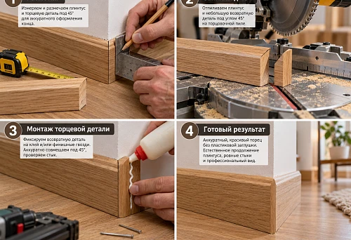
Возвратом называют завершение, при котором основной профиль через угловое соединение продолжается короткой деталью в сторону стены. Лицевой рельеф огибает конец, и линия заканчивается у основания вместо видимого поперечного среза.
Для горизонтального пояса на вертикальной стене такой поворот рассматривают в плане: профиль направляется к монтажной плоскости. Это другой узел, чем поворот рамки вверх или вниз на той же стене.
Возврат можно предусмотреть возле проёма, шкафа или в конце отдельно стоящего участка. Проверьте, что короткую деталь можно изготовить из выбранного сечения, соединить и установить без изменения рисунка. Её длину определяют по конкретной геометрии узла; универсальной прибавки, равной ширине молдинга, здесь нет.
If the termination is set back from the door or furniture, the dimension is tied to the outermost point of the finished assembly. The start of the angled cut and the actual boundary of the assembled return may not coincide. Show on the drawing to which point the clear field is measured, otherwise the visual setback will change after assembly.
Before series cutting, assemble a trial termination. Even a small return must have its own designation in the parts list, otherwise it is easily overlooked when calculating material.
When a straight termination is acceptable
A visible straight end face is possible if it is provided for by the composition, carefully prepared, and finished using a technology suitable for the product. A calm, compact section sometimes makes it possible to do without an additional turn. A deep multi-stepped relief requires a more careful assessment from the side.
If the end is covered by another fixed part, this is a closed junction. It also requires dimensions: the overlap must actually conceal the end face and not create a conflict during assembly.
Do not count on the visible cut disappearing after painting to match the wall color. The coating changes the color of the surface but preserves its geometry and shadow.
Four solutions near the door casing
At the door, first determine the role of the line: a standalone frame, a horizontal band, or part of a portal. Then choose the method of termination.
| Solution | When to consider it | What to show in the detail |
|---|---|---|
| Finish before the casing | There must be a free field between the frame and the door | Offset and end shape |
| Bring to the casing | The line must adjoin the door trim | Cross-section, depth, and contact surface |
| Continue above the portal | The horizontal unites several wall sections | Height mark and transition above the opening |
| Go around the portal | The contour follows its architecture | All turns and free intervals |
The offset is set in the project taking into account the scale of the profile and the door. A universal distance for any casing does not work here. On a narrow wall section, a short residual segment may look accidental; sometimes it is more reasonable to change the entire frame.
If the line goes around the door, do not treat the upper section as an independent decoration. Check how the verticals transition into the horizontal and whether the chosen orientation of the relief is maintained.
Compare the projection of the molding and the casing from the common plane
The width of the casing in the frontal view does not show whether it can receive the end of the molding. A section is needed that shows the base, the installation layers, and the actual position of the face surfaces.
Compare the surfaces specifically at the point of contact. The maximum thickness of the casing in its middle part does not describe an edge with a bevel or rounding. The molding may protrude in front of this edge even when its depth is less than the greatest thickness of the door surround.
A conditional example: the depth of the molding is 12 mm, and the height of the casing surface above the base in the adjoining zone is 9 mm. If their installation planes and installation layers coincide, the molding will protrude by 3 mm. Such a difference may be part of the design intent, but with accidental adjoining it will leave a noticeable step.
Possible solutions are a different profile, a different door surround, an offset with an independent termination, or a specially designed transition. The choice depends on which project elements are already fixed. Reducing the depth of the product only in the model is not allowed.
Near built-in furniture, check the movement of the fronts
The cabinet may come almost flush to the wall, leaving little space for the relief. In the elevation drawing, the molding and the furniture do not intersect, but when opening, the leaf or pull-out front can catch on the protruding profile.
Check the furniture's movement path in plan and section. Account for the actual thickness of the front, hinges, handle, and the clearances specified by the furniture design. The required offset is determined by this detail, not by a single frontal distance.
The wall molding can be terminated before the cabinet, returned to the wall, or the layout can be changed. If the line must visually continue onto the front, the wall decor and the movable door are designed separately. They must not be joined by a single rigid element across the working clearance.
Specify the installation sequence in the design. The end that must be concealed behind the fixed side panel needs to be checked before its installation; later, access to the joint may be limited.
A niche requires choosing a route
A niche has several independent solutions. The line can terminate on the front wall to the left and right of the opening. Another option is to continue onto the side panels and back wall. A third is to frame the niche with its own border, maintaining a connection to the main composition by height or axes.
For a continuous run, each transition between planes is checked. On a short side panel, a large profile sometimes leaves only turns without a readable straight section. Such a fragment should be considered at real scale: the decorative line may turn into an overly tight junction of several reliefs.
The path through the depth of the niche also changes the linear footage. A nominal trajectory with a rear section of 1200 mm and two side sections of 300 mm each has a length of 1200 + 300 + 300 = 1800 mm. This is the length of the specified route; the finished dimensions of the segments are refined based on the joints and the measurement line.
If the band remains only on the front wall, it has two independent terminations. They need to be drawn, not connected by a line across the void of the niche.
Arch: check the shape, direction of curvature, and execution
Polyurethane moldings for an arch are selected to match the actual curve. First, the radius or the full geometry of the contour and the position of the profile relative to the opening are determined. An arch on a flat wall and a run around a cylindrical surface require bending in different directions.
For the selected product, confirm the availability of a flexible version, the permissible radius in the required direction, and the installation conditions. The mere indication of "polyurethane" does not mean that any straight strip can be bent. The limitations of another model or another manufacturer do not replace the data for the required item code.
Clarify which line the radius on the drawing refers to: the edge of the opening, the axis of the molding, or its mounting surface. It must be compared with the permissible radius of the product according to the manufacturer's accepted scheme. The offset of the profile from the edge of the arch changes its trajectory, even if the shape of the opening itself remains the same.
If there is no suitable version, change the profile or the geometry of the trim. Arbitrarily bending a three-dimensional model does not create a corresponding product.
For a non-rectangular opening, keep a dimensional drawing of the curve. Two numbers — width and height — may not be enough: a semicircle, an arc, and an oval with similar overall dimensions have different trajectories. This difference also determines the shape of the transition to the vertical sections.
Transition from straight molding to flexible
At the joint, the width, depth, face relief, and orientation must match. A matching collection name is not enough. The straight and flexible parts are checked as a specific pair of products.
For a smooth transition, the directions of the trajectories must coincide at the joint: the straight section continues tangent to the arc. If a section with a different direction starts immediately from the vertical, a geometric break appears that painting will not eliminate.
However, matching tangents alone does not yet confirm the quality of the joint. Check the local position of the profile, the absence of twisting, and any step on the face surface. On a sample, join both versions with the selected finish.
In the documentation, note the transition point and the lengths of both parts. Do not record the entire route as a single linear footage of straight molding, even if after installation it should be perceived as a continuous line.
Around a column and at the boundary of zones, the line may be interrupted
First decide whether the column actually needs to be wrapped. For a round surface, this means checking the radius and flexible execution; for a rectangular projection, several outer corners. A small column size can make the selected wide profile too tight for such a route.
An alternative is to end the band before the column, finish it separately, and continue the line on the next section. A shared height mark can preserve the compositional connection without joining the parts.
A deliberate break is also appropriate near a large portal, at a change of finish, ceiling height, or functional zone. Mark it in the design and set the same termination logic on both sides. Then the pause becomes part of the architecture.
There is no need to surround every projection just for continuity. If the detour creates several short segments and complicates the joints without a clear visual result, reconsider the route.
How to bring a vertical up to the ceiling cornice
Check the section of the upper wall zone. A vertical molding can end below the cornice with a specified gap, abut a particular surface, or enter a joint with additional decor. The decision depends on the geometry of both products.
If the cornice overlaps the termination, show the actual overlap depth and the assembly sequence. A front view does not explain whether the molding will fit behind the lower part of the cornice. On-site trimming should not be the only description of the joint.
Polyurethane moldings and cornices are also assessed together: close parallel horizontals can either support a common band or create accidental doubling. Compare them from a normal viewing point in the room.
For a ceiling frame, mark the dimensions of the light fixtures on the plan and ceiling rose. The meeting point of the lines with the central trim should be defined as precisely as the abutment to the door.
The ornament must be aligned on both sides of the turn
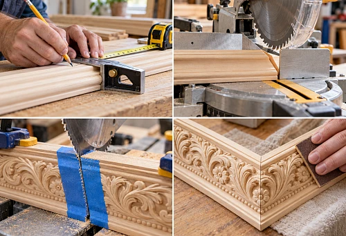
For a smooth profile, the cross-section match is checked. For ornamental trim the pattern direction, its repeat, and the position of the motif relative to the corner are added.
A geometrically tight joint may cut through a large sheet or place two mismatched parts of the ornament side by side. First lay out the pattern over the entire area, then choose the cut locations. For symmetrical framing, check both sides of the central axis.
If the pattern does not align, consider a coordinated decorative element, a different profile, or changing the length of the section. You must not stretch an individual motif in the model and consider that a solution for a serial product.
When selecting Polyurethane trim, in the task, preserve not only the lengths but also the required start of the pattern. A leftover that fits in size may be unsuitable for a specific ending.
What to show on the drawing of a complex assembly
The general layout defines the location of the assembly. Its structure is revealed by a separate enlarged fragment. Choose the projection that shows the cause of a possible conflict.
| Node | Main check | Required image |
|---|---|---|
| Junction to the architrave | Overhang and contact surface | Unfolded view and cross-section |
| External wall corner | Turn between planes | Unit plan and section |
| Return of the horizontal band | Shape of short part and wall termination | Plan and end view |
| Transition into niche | Sequence of turns | Niche plan and unfolded views of its surfaces |
| Transition to arch | Trajectory, tangent, and section | Dimension curve and joint fragment |
For the selected products, use DWG drawings and STAVROS 3D models. Verify the item code, size version, and orientation. The general model archive does not confirm that the required assembly has already been developed for the designer.
The drawing must clearly show the base, dimensions, both mating parts and the assembly sequence. If some data still requires clarification, note this before releasing the task for work.
The 3D model verifies the perception of the assembly
Show the outer corner, return and niche from the direction from which they will be seen in the room. A close-up is useful for evaluating the shape, but it must be supplemented with a general view: a neatly executed assembly may turn out to be too noticeable in the wall composition.
Use actual cross-sections, identical finish, and the intended lighting. Side light helps reveal the steps and sharp changes in relief. Check whether a dark spot appears near the end that is not present on a long straight section.
If the result is unsatisfactory, change the assembly or choose a different product. Arbitrarily reducing the depth and smoothing an inconvenient end in the model hides the problem until installation.
A trial assembly is needed for repeating ends
For a complex or repeatedly recurring assembly, assemble a fragment from the actual profile, the mating part, and a section of the base. For a return, a short closing piece is needed; near a door, a sample of the corresponding casing; at an arch, both parts of the transition.
First check the geometry and feasibility of assembly, then the chosen finish system. Look at the sample from the front and side under typical lighting. Record the accepted orientation, dimensions, and method of termination so that the next such assembly is not reassembled by guesswork.
If the composition includes Polyurethane decorative appliques, try the specific element as a whole. The overlay should not hide an unresolved junction in only one frontal view.
An approved sample applies to specific products and conditions. Changing the cross-section, base, or adjacent part requires rechecking the affected part of the assembly.
After the assemblies, compile a list of parts and the order
The working list includes main straight sections, flexible versions, short returns, corner elements, and ends. For each segment, the length and geometry of both ends are determined. Piece decor is counted separately.
A single designation like "molding — 42 m" is not enough. Link each group of parts to an article number and a node, then distribute the segments across product bars. Short returns also consume material and require processing; they cannot be counted automatically as free leftovers.
Separate rows are kept for the left and right decor. Straight and flexible versions are also not combined, even if they form a single line. The reserve is determined after checking the cutting plan and the repeatability of complex areas.
Changing the ending can change the length of the main section. Therefore, after approving the trial node, update the list of segments and the purchase quantity, not just the image on the layout.
Errors worth checking before purchasing
Most often, unresolved areas are found where a beautiful overall line hides specific geometry. Go through the route sequentially and check:
- each open end has a selected finishing method;
- the frame corner is not confused with the turn between walls;
- the finished decor is compatible with the profile and fits entirely;
- the mirrored part exists under a separate article;
- the junction with the casing has been checked in section;
- the furniture opens without touching the molding;
- the execution and bending conditions are confirmed for the arch;
- the straight and flexible sections are aligned at the transition point;
- the ornament has been checked at the cut points;
- short returns are included in the parts list.
If at least one junction is marked only with the words "resolve on site," clarify what information is missing. Measuring the actual base may be part of installation; the choice of architectural termination method must be made in advance.
Where to order architectural moldings for ready-made junctions
After fixing the trajectory and junctions, you can buy polyurethane moldings for a specific layout. In the order, specify the item codes, dimensions, executions, and the quantity of whole strips, and for the decor — individual piece items.
Check the current price, availability, and delivery terms of the selected composition. The cost of the solution depends not only on the linear meters of the straight profile: it is also affected by additional elements, cutting, and the specified complex terminations.
Related products are selected in the catalog moldings from polyurethane, the procedure for professional collaboration is specified on the page for designers and architects.
Submit the set of approved assemblies and the list of parts together with the order. The installation task then receives a specific description: which profile runs along each section, how it turns, and how it ends.