

























Article Contents:
- Carved table base STL-012: what is included in the original specification
- Why 900×760×332 mm is not a mounting scheme for the tabletop
- What information to gather about a ready-made quartz tabletop
- How to create a hole map without orientation errors
- Matching centers does not mean matching mounts
- What partial matching of old holes means
- Mismatched holes: when a stone workshop is needed
- Weight of the ready-made tabletop: what data to provide to the manufacturer
- How to overlay STL-012 on the countertop plan
- Overhangs and height: what to recalculate after changing the mounting unit
- Why symmetry and neat assembly do not yet prove stability
- Disassembled STL-012 delivery: two assemblies instead of one
- Beech or oak: choose after confirming compatibility
- How to coordinate the finish without losing mounting accuracy
- Price of STL-012 and budget for replacing the old base
- When it is better not to order STL-012 for an existing top
- How to search for an alternative in the underframe catalog
- What to send to STAVROS and the countertop manufacturer
- How to place an order without undefined items
- Check after receiving the underframe and before final installation
- Questions before replacing the base
- Do I need to keep the old base until the new one is installed?
- Can compatibility be fully checked remotely?
- What to do if the old fasteners are lost?
- Can I rely on the old invoice that only says "quartz"?
- What to do if the old holes are not symmetrically positioned?
- Can unused holes be closed independently?
- Will an old mounting plate work as an adapter?
- What to do if the threaded insert spins?
- Is it acceptable to slightly file down a wooden part to preserve the stone?
- Can a mismatch be fixed with a longer screw?
- Is a printed template suitable for checking?
- What to do if the document for the base and actual measurements differ slightly?
- Can two STL-012 underframes be installed instead of one?
- Will the check change if the tabletop is oval but its dimensions are also 1600×900 mm?
- Can old foot pads be kept and not included in the project?
- What to do if the base needs to be replaced without removing the tabletop?
- Can the table be moved after assembly by holding onto the stone top?
- Can the tabletop be rotated 180 degrees to align the holes?
- Is it worth ordering spare hardware along with the underframe?
- Should access to the fasteners be left after final installation?

A quartz tabletop measuring 1600×900×30 mm has already been manufactured. On the underside, there are holes and possibly inserts from the previous base. The base itself is no longer satisfactory: it needs to be replaced with a carved wooden underframe STL-012, preserving the expensive top. Can a new model be ordered and the existing fastening be used?
This option can be considered, but compatibility cannot be confirmed based only on external dimensions. Before payment, the mounting diagram of STL-012 must be compared with the hole map of the tabletop, the condition of the old fastening units must be checked, and the load transfer between the stone and the wooden structure must be coordinated. If the points do not match, the decision on rework is made by the tabletop manufacturer together with the person responsible for the table structure. The buyer should not independently drill into quartz or reduce the number of fasteners.
The base dimensions of 900×760×332 mm answer the question about its size. They do not show where the holes of the upper assembly are located, which areas support the tabletop, and what fasteners are required specifically for it. Even beautiful centering under the finished top does not yet indicate the possibility of assembly.
Let's break down this procedure using a calculation example. The tabletop size is assumed for the situation in question; the hole coordinates and additional dimensions in the examples below are conditional. They explain the verification method but are not a mounting drawing of STL-012.
Carved table base STL-012: what is included in the original specification
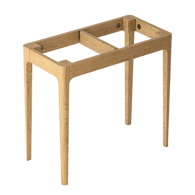
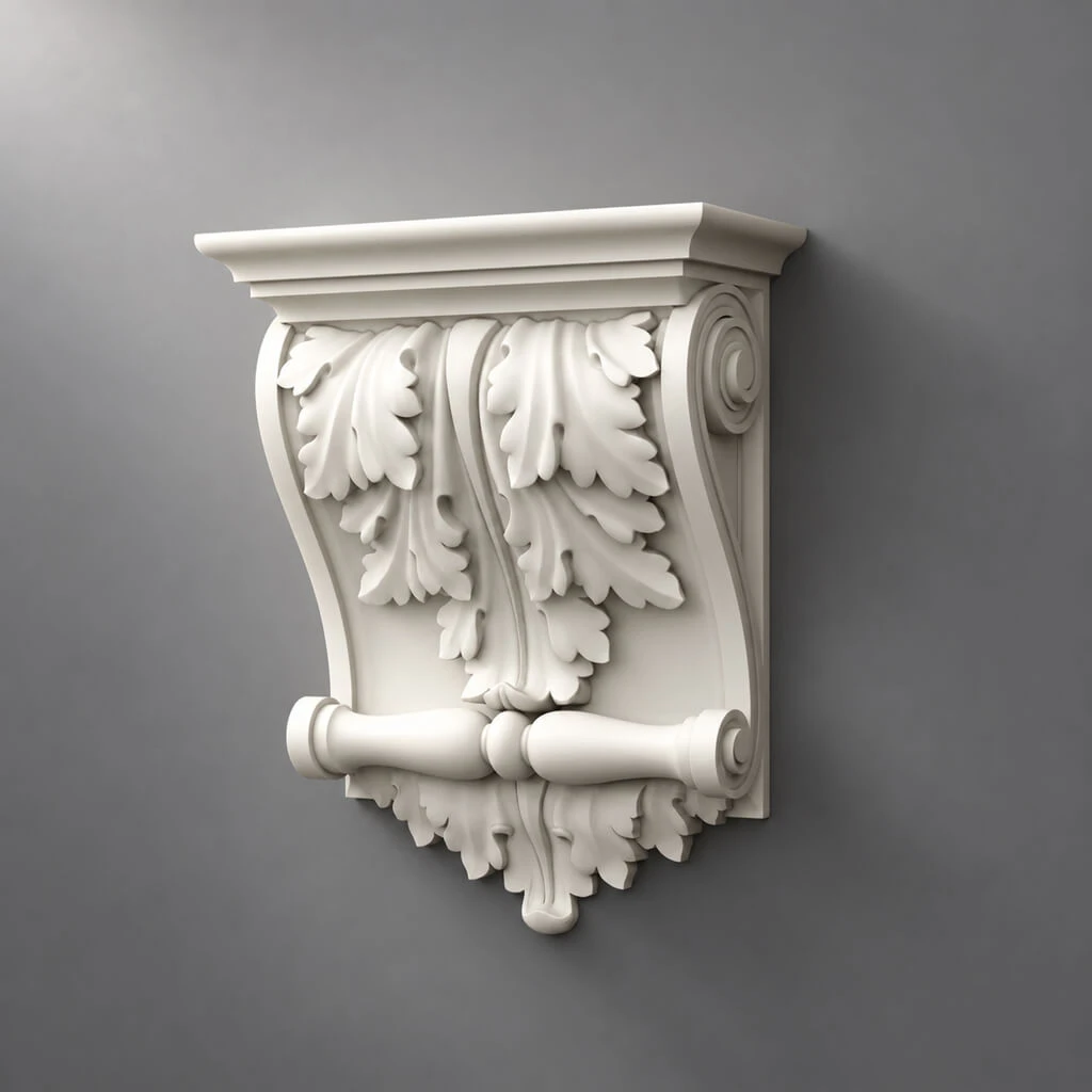
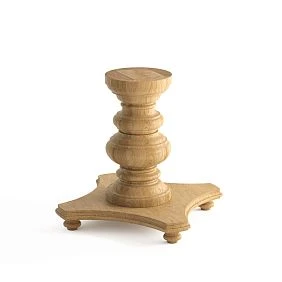
Start with the exact article number, not with a photo of a similar base. In the card of the carved table base STL-012 the following parameters are specified.
| Parameter | Version STL-012 |
|---|---|
| Dimensions in the card notation A×B×D | 900×760×332 mm |
| Wood | Beech or oak |
| Sanding quality | "Standard" or "Prestige" |
| Preparation of the selected beech version | For enamel |
| Construction | Composite product |
| Default delivery | Disassembled |
| Hardware for assembling the product | Included in the set |
| Delivery in assembled form | By separate agreement and calculation of assembly |
There is no promise here that any stone top of the appropriate length can be installed on the standard set. The upper support area, the method of connection to the tabletop, and the suitability of existing embedded elements must be defined separately.
Also specify exactly what is included in one product item. For a composite product, the number of decorative parts, the number of support contacts, and the number of packages are different values. Do not order several sets based on the number of carved elements visible in the photo. In the order under consideration, one STL-012 underframe is initially discussed; the need for a different quantity or a different design should follow from the project, not from a guess.
The inscription "under enamel" also requires correct interpretation. It does not mean that the box contains an already painted white base. The choice of wood and surface preparation must be separated from the order of the final coating. Otherwise, after solving the installation task, it will turn out that painting work remains before installation.
For correspondence, it is convenient to keep one specification of the selected option. If you first discussed beech and then switched to oak or changed the quality of preparation, update the entire document. A response to an old request should not imperceptibly become confirmation of a new configuration.


Why 900×760×332 mm is not a mounting diagram for the tabletop
The base has several different contours. The outer contour shows the extreme protrusions of the product. The upper support area describes the zones through which the load from the tabletop is transmitted. The mounting diagram determines the position of the connections. Contacts with the floor belong to yet another geometry. None of these contours can be substituted for another.
For example, a wide carved part may protrude further than the mounting platform. Then the distance between the extreme points of the silhouette will be greater than the useful mounting width. Another design is also possible, where the upper parts are offset relative to the lower supports. No option can be designated as STL-012 based on a general photo: a drawing of the specific product is needed.
Keep dimensions A, B, and D in the manufacturer's designations. Before using any number as the table height or support width, find the corresponding dimension line on the drawing. The order of numbers in the product name by itself does not replace an oriented side and top view.
Before ordering, request a general dimensional drawing and a separate image of the upper connection node. It must clearly show the base axes, mounting coordinates, dimensions of contact surfaces, and the joint design. If an intermediate element is provided, it must also be included in the diagram, not appear later as an installer's improvisation.
It is useful to clarify which tabletop the standard node is shown for. A connection designed for a wooden top cannot be transferred to quartz agglomerate without verification. Even the same hole layout does not make the mounting depth, fixation method, or joint performance identical.
A buyer who is going to buy an underframe for a tabletopThe answer needed is not "it will fit in size," but a more specific one: which exact top, through which node, and in what position it is allowed to be installed. Such an answer allows moving from choosing on the showroom floor to agreeing on a specific table.
Our factory also produces:

What information to gather about a finished quartz countertop
An already manufactured countertop becomes the initial constraint of the project. Therefore, it needs to be described as a separate product, not as a rectangle of stone. Start with the documents from the previous order: they may contain the material grade, cutting layout, actual thickness, substrate structure, and data on embedded elements.
The external dimension of 1600×900 mm does not tell the whole story about the underside. There may be glued elements, an old mounting plate, local reinforcements, or remnants of fasteners underneath. All of this must be reflected in the diagram. If any area is covered by an old base, mark it as inaccessible for inspection, rather than drawing a conditionally free surface there.
| What to fix | Why this will be needed |
|---|---|
| Length, width, shape, and rounded corners | For the position of the new base relative to the top |
| Slab thickness and edge construction | To understand the actual cross-section of the product |
| Exact material name | To contact the manufacturer with a specific inquiry |
| Weight of the finished countertop | To assess the base and connection joint |
| All old mounting points | For comparison with the new installation diagram |
| Diameters, available depth, thread information | To check compatibility of fastening elements |
| Substrate, reinforcements, and embedded parts | To determine the actual load transfer path |
| Chips, cracks, signs of displacement | To decide on the suitability of the existing connection |
| Condition of the old base | To understand the reasons for replacement and the structure of the previous assembly |
Do not record the outer thickness of the decorative edge as the stone thickness at any point. If the edge is formed by multiple parts and the middle has a different cross-section, these differences are significant for design. An unknown structure is better left as a question for the manufacturer than filling the column with a convenient number.
Take photos with reference to the markings on the map. A general view of the underside helps to see the location of the joints, while individual shots show the condition of each point. A close-up frame without a hole number is of little use: the contractor will not be able to reliably associate the damage with a specific location on the drawing.
Do not flip or lift a heavy tabletop alone for a missing shot. If there is no safe access from below, inspection and dismantling of the old base should be organized with specialists. First, determine the method of handling the product, then take measurements.
Get Consultation
How to create a hole map without an orientation error
For comparing the old mounting with the new one, a unified coordinate system is needed. For a rectangular tabletop, it is convenient to take the left front corner as the origin: X directed along the 1600 mm side, Y along the 900 mm side. The diagram must indicate where the front side of the table is and from which side the product is shown.
For the selected rectangle, the geometric center is at point X=800 mm, Y=450 mm. Each hole gets its own number and a pair of coordinates. Even with obvious symmetry, it is better to record all points separately. This allows noticing the actual offset that would be lost in the description "four holes at the corners".
The most unpleasant error occurs when transitioning from a top view to a bottom view. If the tabletop is flipped, the left side in the photo may correspond to the right side of the original plan. After such a mirrored transfer, completely incompatible diagrams may sometimes appear to match.
Choose one representation method and label it with words. For example: "Fastening points are shown in projection onto the top view of the tabletop; the front edge is indicated by an arrow." Bottom photos are then used for inspection, and coordinates are referenced to the selected projection. If documentation is prepared by a workshop, ask it to perform this referencing rather than correcting image orientation by eye.
A rounded tabletop may not have a physical sharp corner. In such a case, the coordinate origin is set by the intersection of agreed baseline lines of the bounding rectangle. An offset from an arbitrary point on the rounding is not suitable: two people can easily choose different points and get different distances.
The hole table requires coordinates of axes, not distances to the nearest visible edge of the hole. If an insert is present, distinguish separately its outer contour and the axis of the threaded connection. Do not label everything with a single entry "diameter about ten": it does not explain which element was measured.
Add the measurement date, units of measurement, and the method of data acquisition. A value from an old drawing and an actual measurement are not the same thing. If they differ, keep both records until the cause is verified. Do not average them to get an "approximately suitable" result.
Measurement accuracy must also be clear. A distance estimated from a photo cannot be presented as a dimension with millimeter precision. At the preliminary stage, such an estimate can help filter out obviously unsuitable schemes, but it will not serve as a basis for final assembly.
Coincidence of centers does not mean coincidence of fastenings
Consider a conditional map of four old holes. It is needed only to explain the method; it is not a drilling pattern for the tabletop or the layout of STL-012 fasteners.
| Point | X, mm | Y, mm |
|---|---|---|
| P1 | 300 | 250 |
| P2 | 1300 | 250 |
| P3 | 1300 | 650 |
| P4 | 300 | 650 |
Between the left and right rows, the distance is 1000 mm; between the front and back, it is 400 mm. The center of this group coincides with the center of the tabletop: 800×450 mm.
Suppose the mounting points of the base being compared form a rectangle of 960×400 mm, and the base is also centered. Then the conditional coordinates of the new points will be different.
| Point of the new node | X, mm | Y, mm | Deviation from the corresponding old point along X |
|---|---|---|---|
| Q1 | 320 | 250 | +20 mm |
| Q2 | 1280 | 250 | −20 mm |
| Q3 | 1280 | 650 | −20 mm |
| Q4 | 320 | 650 | +20 mm |
Both groups are symmetrical about the same axes, but no pair of mounts fully coincides. The difference between center-to-center distances is 40 mm; when centered, it is distributed as 20 mm on each side.
Shifting the base to align all points is impossible here. If you move it 20 mm to the left, the left row will match the old one. The right one will be at X=1260 mm instead of X=1300 mm—the discrepancy increases to 40 mm. One successful match does not fix the difference in the shape of the entire group.
For any new layout, it is useful to compare not only the overall center but also the distances between corresponding points. If the configuration itself differs, moving the entire base will not solve the problem. If the configuration is the same and only the position differs, the possibility of shifting is still checked against support, overhangs, and ease of installation.
For a complex top assembly, it is not necessary to reduce everything to a rectangle. Mounting points may form a different shape. Then the actual coordinates and purpose of each point are compared. Adjusting the image in an editor by changing proportions is not allowed: a stretched picture of the base will no longer correspond to the product that will arrive in the box.
The result of such a comparison should look like a mark for each connection: matches, does not match, or not yet checked. The phrase "generally similar" does not help either the countertop manufacturer or the installer.
What does partial matching of old holes mean
The situation "two points matched, two did not" does not allow using only the matched pair. It is necessary to know the role each connection plays in the new joint. The position of fasteners is part of the structure, not a set of equivalent locations from which the most convenient ones can be chosen.
At the same time, it is not required to automatically use all the holes left from the previous base. Suppose there are eight of them, and the new agreed connection uses four other design points. The mere presence of four unused holes does not prove an error. What is checked is the completeness of the new scheme and the condition of the remaining areas, not the ratio of occupied holes to the total number of old ones.
Hence two different questions. First: are all necessary points of the new joint present in the existing countertop? Second: is it permissible to reuse each of them? A positive answer to the first does not replace the second.
Even when coordinates match, the joint design may differ. In one place there is a threaded insert, in another a hole in the old mounting plate, in a third the fastener was held in the substrate rather than in the stone. A visible circle on the bottom surface does not explain which base the screw worked with.
Therefore, the map is supplemented with a description of each point: type of element, known marking, condition, and whether it belongs to the stone, substrate, or a separate part. If the thread designation is unknown, it is not restored by picking a random screw with force. It is better to hand over the old fastener and information about the previous order to a specialist.
Signs of repair are noted separately. A point that looks neat from the outside may have been restored after damage or installed differently than neighboring ones. The owner is not obliged to determine its load-bearing capacity on their own. Their task is not to hide uncertainty in a general note like "all holes are sound."
Hole mismatch: when a stone workshop is needed
If the map has shown a discrepancy, the next step is to discuss the possible joint with the countertop manufacturer. It cannot be assumed that missing points can always be added and old ones left nearby without consequences. The permissibility of modification depends on the specific product and its condition.
New holes, changes in depth, restoration of embedded parts, or reworking the substrate should not become independent DIY work based on advice from an article. There is no universal solution like "take a different drill bit" here. The manufacturer of the stone top must assess the material, accessible areas, and permissible processing method.
The first option for discussion may be to preserve existing sound embedded parts and develop an intermediate mounting piece. It connects two different schemes, if such a design is permissible at all. But the existence of this idea does not mean that a ready adapter exists for STL-012 or that it can be made from an arbitrary plate.
The intermediate element has its own requirements: rigidity, method of contact with the top, connection to the wood, access to fasteners, and final height. It must transfer load according to the agreed scheme, not just geometrically connect mismatched holes. The material and thickness of such a part are assigned by the person responsible for the structure.
The second option is to modify the existing mounting assembly of the countertop in the workshop, if permitted by the manufacturer. The third is to select a different underframe that better matches the already finished top. Sometimes keeping part of the old support system is discussed, but its condition and compatibility also require verification.
| Inspection result | What to discuss next |
|---|---|
| All necessary points match and are suitable | Confirmation of full connection and assembly order |
| Coordinates matched, fastening device differs | Coordination of corresponding connecting elements |
| Some points do not match | Intermediate node project or other basis |
| There are damaged or unknown embedded parts | Inspection and decision of the countertop manufacturer |
| Changing the top is not allowed | Base for existing scheme or preservation of previous design |
A budget-risky path is to first buy and finish a base you like, then try to justify the purchase with any stone rework. It is much more useful to get a conclusion about the feasibility of joining before expenses that are hard to undo arise.
Weight of the finished countertop: what data to provide to the manufacturer
In the compatibility request, you need to report the weight of the finished top specifically. The wording "a regular quartz countertop 30 mm thick" is insufficient. Different materials and the structure of the underside should not be reduced to one approximate weight.
For a rectangle of 1600×900 mm, the area is 1.44 m². If we conditionally assume that the entire slab is homogeneous and has a solid thickness of 30 mm, the geometric volume will be:
1.6 × 0.9 × 0.03 = 0.0432 m³.
The mass calculation in such a simplified case is written as m=0.0432×ρ, where ρ is the confirmed density of the specific material in kg/m³. Without this value, the calculation is incomplete. Substituting a random density of "any stone" and presenting the result as the actual mass is not allowed.
If the countertop has rounded corners, cutouts, a glued substrate, or a thickened edge, the model of a solid rectangular parallelepiped no longer describes the entire product. For an order, it is better to obtain the mass from the manufacturer. Permanently attached elements that will remain on the new base are considered separately.
In the detailed description of STL-012, there are general load guidelines. However, they do not describe your drilled slab, the condition of its embedded parts, or the specific connection method. Therefore, they cannot be turned into automatic approval for installation. Ask the manufacturer to confirm the applicability of the chosen structure to the specified mass and the agreed-upon scheme.
The calculation does not end with the tabletop's own weight. The table will have a purpose: family dinners, work, equipment placement, or another scenario. Describe the expected use, especially permanent heavy items and their positions. This is more useful than asking for a "maximum kilograms in general."
There is no need to independently check the safety margin by sitting on the edge or loading the structure with random weights. Such actions do not replace approval and may damage the already manufactured product. Testing conditions are determined by the specialist responsible for the finished assembly.
How to apply STL-012 to the countertop plan
Once an oriented base drawing is obtained, a combined scheme can be prepared. For holes, a top view is needed, and for height, a separate side view. A frontal image of the thread is useful for composition but does not replace either of these documents.
The plan must distinguish the tabletop contour, external protrusions of the underframe, the upper contact zone, and fastening points. If all lines are marked identically, it is easy to mistake a decorative protrusion for a support location. Labels matter more than pretty graphics: the scheme is intended for comparing dimensions, not for interior presentation.
The initial position of the base can be set at the center of the tabletop. For a symmetrical rectangle, this is a clear starting point, but not a universal rule for final installation. Then, mass distribution, support shape, and requirements of the specific connection joint are evaluated.
If points on the underframe drawing are specified relative to its own center, they need to be converted to the common system. With no rotation and coincident centers, the tabletop coordinates are obtained by adding 800 mm to the longitudinal coordinate of the point and 450 mm to the transverse one. The axis directions must coincide; a mirrored bottom view cannot be used in such an operation.
For a complex hole pattern, it is more convenient to entrust the overlay to the person preparing the installation documentation. The buyer checks that the correct article number, the valid map of old points, and the agreed orientation are used. Do not manually stretch a photo of the new base to make the required circles align with the old holes.
After any shift, the entire plan is updated, not just one dimension label. Distances to edges, positions of carved parts, and space for chairs change. One fixed fastening conflict can create another, no longer related to holes.
The final document must have a date or version number. Otherwise, the stoneworker may evaluate the first scheme, the base manufacturer the second, and the installer receive a third. Compatibility is confirmed for one and the same arrangement of all parts, not for a set of disparate sketches.
Overhangs and height: what to recalculate after changing the mounting joint
Overhangs are measured relative to the boundary specified by the designer: the upper support zone or another defined element. Measuring to the outermost carved protrusion does not always answer the question about the countertop's support. The record must explicitly name the chosen boundary.
Let us show the arithmetic on a hypothetical example, not related to the actual dimensions of the upper joint STL-012. If the rectangular support zone is 1000×400 mm and is centered on a 1600×900 mm tabletop, the distances to the edges will be as follows:
Left and right: (1600−1000)÷2=300 mm.
Front and back: (900−400)÷2=250 mm.
These results are not permissible overhangs for quartz. They only show the geometry of the adopted example. Whether such a scheme is suitable must be confirmed by the person responsible for the structure, taking into account the material, cross-section, and connections.
If the same hypothetical support zone is shifted 25 mm to the right, the left margin increases to 325 mm, and the right margin decreases to 275 mm. Therefore, the proposal "let's shift it under the old holes" changes not only the position of the fasteners. After the shift, a re-evaluation of the entire assembly is required.
The height of the finished table is also calculated after final assembly. In the simplest geometry, this is the vertical dimension of the base plus the actual addition of the connecting joint and the thickness of the tabletop above it. If some parts are nested inside each other, their full thicknesses cannot be added: a cross-section diagram is needed.
For example, replacing an intermediate layer with a vertical addition of 8 mm with a variant with an addition of 20 mm raises the top by 12 mm, if other elements remain unchanged. The values here are conditional. They explain why, after choosing the transition joint, it is worth re-checking the height rather than taking it from the initial sketch.
The space under the table is measured separately. A new part may end up lower than the bottom surface of the stone and interfere with knees or armrests. The top surface mark may sometimes remain convenient. Therefore, the working drawing needs both boundaries: the top level and the lowest part in the seating area.
Why symmetry and neat assembly do not yet prove stability
Equal overhangs help assess the appearance. They do not replace a structural check. For a finished table, the mass and position of parts, lower contacts, upper support scheme, and joint performance matter. Even with perfect symmetry, the allowable load cannot be assigned based on a single image.
Discuss the table's purpose together with the chair arrangement. If the underframe must be shifted for holes, carved parts may end up in front of the knees on one side. Then a geometrically possible connection does not provide a comfortable dining spot. The check should be for normal seating, not for a person's position deliberately moved away from an obstruction.
A paper or lightweight full-size mockup helps assess the base projection and free space. But it does not simulate the mass of a quartz top, joint rigidity, or stability. Such a fitting has a limited purpose: to check placement. It should not conclude that the heavy tabletop can already be installed.
Fastening and support also cannot be considered a single function. One element may hold parts against relative displacement, while another takes vertical load. A coincidentally matching screw does not prove that the countertop received the necessary support on its underside. The design must make clear through which surfaces and connections forces are transferred.
When discussing the floor, report level differences at the installation site and planned leveling feet. Do not eliminate rocking with an arbitrary stack of shims, which changes how the base works. The leveling method and any permissible additional parts should be agreed upon before final acceptance of the table.
Disassembled delivery STL-012: two assemblies instead of one
For this model, you need to separate assembly of the wooden underframe itself from attaching the finished countertop. The included hardware pertains to the composite product. This information cannot lead to the conclusion that the box contains suitable parts for any stone or any old embedded anchors.
Before ordering, request a list of components and instructions. The installer needs to understand which connections are formed during base assembly, which operations are performed before finishing, and which parts must then remain accessible. Do not start work on the countertop until the underframe itself is assembled and checked against the agreed documentation.
If an assembled STL-012 is needed, such a delivery can be discussed separately: the card provides for requesting an assembly quote through a manager. But the assembled base still does not become a finished table. The quartz top with existing holes remains a separate part of the order, requiring its own mounting solution.
For the final configuration, it is convenient to make three lines: underframe hardware, connection elements to the tabletop, and additional design parts. Opposite each, the supplier and installation contractor are indicated. This reveals a situation where the manager considers the transition part to be the stoneworker's job, while the latter expects to receive it together with the base.
Also pay attention to the access order. The connection may be visible on a separate drawing but turn out to be inconvenient after the adjacent element is attached. The assembler must confirm in advance the sequence of operations and the ability to work with tools in the intended places.
Keep the old fasteners until inspection, but do not automatically assign them for reuse. After changing the connection joint, the previous screw length or head shape may not match the new assembly. Clarifying the fastener composition should precede installation, not boil down to finding a suitable box on delivery day.
Beech or oak: choose after confirming compatibility
The wood species does not correct the difference between mounting schemes. If the base cannot be connected to the existing top in an acceptable way, switching from beech to oak will not solve the problem. Therefore, choosing the material makes sense after the geometry, weight, and design joint are understood.
A beech underframe for enamel coating is logical to consider for opaque finishes: white base, kitchen facade color, or another agreed shade. In this case, the coating itself must be approved. The name of the preparation does not determine the color, gloss level, or final painting technology.
An oak underframe with visible texture is chosen when the wood grain should participate in the composition along with doors, parquet, or furniture. But the species name does not guarantee shade matching. It is better to compare a physical sample of the future finish with those items already in the room.
The finished quartz top also has its own features: background tone, pattern, gloss, edge profile. Evaluate the wood sample next to the real stone, not with two separate photos on a screen. Contrast sometimes looks more convincing than trying to achieve almost the same shade of different materials.
For a transparent or semi-transparent coating, the quality of wood lamella selection is separately clarified. In in the description of materials and quality of STAVROS preparation for enamel and for toning differs precisely in the requirements for selecting the workpiece. This is a separate parameter, not a synonym for "Prestige" sanding. Natural tonal differences in wood are not completely excluded in this case.
Sanding is responsible for the surface condition. 'Standard' involves machine processing; 'Prestige' adds detailed manual sanding, including complex relief. This choice should not be turned into a promise of greater load capacity. The structural compatibility of the table is checked separately.
Ask the finisher to evaluate both options against one final result. If additional preparation is needed for the "Standard" estimate, it must be accounted for. For "Prestige," the requirements of the chosen coating system are also agreed upon, rather than assuming that all subsequent operations have already been completed by the manufacturer.
Solution Buy a wooden table base in this order it becomes specific: first the construction is confirmed, then the wood species, surface quality, and finish are selected. Decorative preferences remain part of the project but do not force risking an already finished tabletop.
How to coordinate finishing without losing installation accuracy
The coating should be discussed together with the assembly sequence of the base. Which parts are finished separately, which zones remain technological, and when the final connection is made—these are questions for the manufacturer and the contractor. A universal sequence for any composite underframe does not apply here.
Before starting the finish, provide the craftsman with the current installation diagram. It should clearly show mating surfaces, support areas, and access points to hardware. Otherwise, a beautiful coating may be applied where a specific fit needed to be preserved or an operation performed in a different order.
Do not change the structure for the sake of painting convenience: removing additional material from a part, relocating fasteners, or covering access with a decorative panel without approval. After such actions, the original confirmation no longer applies to the product being assembled.
When accepting the finish, not only the color of the front carved part is assessed. Side and bottom surfaces are visible from neighboring seats at the table. If an intermediate mounting element comes into view, its appearance is also agreed upon in advance. At the same time, masking should not interfere with servicing the connections.
Before final installation, it is necessary to check that the intended assembly is preserved after finishing. If parts no longer connect in the standard way, the problem cannot be solved by over-tightening. First, determine the cause and coordinate the correction with the contractors.
The finished stone top should not be used as a random work surface for painting operations. A separate suitable place should be organized for finishing and assembling the base. This helps protect the already manufactured tabletop and avoid mixing stages that have different requirements for cleanliness, access, and handling of parts.
Price of STL-012 and budget for replacing the old base
As of the inspection on September 5, 2026, in the size and price table for STL-012 the following amounts were listed for the underframe measuring 900×760×332 mm.
| Material | "Standard" | "Prestige" |
|---|---|---|
| Beech | 122 760 ₽ | 129 030 ₽ |
| Oak | 227 330 ₽ | 238 800 ₽ |
The difference between sanding qualities is 6270 ₽ for beech and 11,470 ₽ for oak. It applies to the selected product variants. This is not the cost of a fully installed table with a custom mounting assembly and painting.
For replacing the base, it is more convenient to split the budget into purchasing the product and preparing a compatible solution. The second part may include inspection of old embedded parts, development of the connection, manufacturing of agreed components, assembly, finishing, transportation, and installation. Not all items will be required in every case; unknown work cannot be declared mandatory in advance.
Compare options with the same final result. If one quote includes base assembly and another shows only the price of the kit in the box, the difference in amounts does not necessarily mean savings. The same applies to transporting a heavy tabletop to the workshop and back.
To choose between adapting STL-012 and another base, two separate estimates are useful. In the first, keep the model you like and include only confirmed compatibility work. In the second, select a base for the existing top and estimate its installation. The price of an already manufactured tabletop does not change in these calculations, but the risk of reworking it may differ.
Do not set the cost of an adapter part based on the area of metal or sheet material. Besides the material, it involves design, fabrication, and suitability verification. Without an agreed assembly, such a number is a guess, not a purchase budget. Before payment, confirm the current price of the selected configuration and the scope of all additional work.
When it is better not to order STL-012 for an existing top
The purchase should be postponed if the manufacturer cannot confirm the suitability of the design for your weight and mounting scheme. This does not mean the base is bad or generally unsuitable for tables with stone. It simply means that for this combination of products, there is not yet sufficient basis to proceed with installation.
Another reason to stop is damaged inserts or an unknown condition of the old mounting area. A nice base does not restore the suitability of the top assembly. First, a solution from the tabletop manufacturer is required, and only then can you choose an acceptable connection method.
If the stone fabricator does not allow new points and a compatible intermediate assembly cannot be developed, it is reasonable
How to search for an alternative in the underframe catalog
The catalog includes STL-007, STL-008, STL-011, STL-012, STL-023, and other bases. Their presence in one category indicates the purpose of the product group, but not identical mounting. For a ready-drilled tabletop, a short technical list is useful, not a selection of visually similar models.
First, select products for which the necessary drawings can be obtained. Then compare the height, shape, and dimensions of the support area, the fastening scheme, the requirements for the countertop, and the delivery configuration. The wood species and finish are considered only for candidates that pass these checks.
If the interior requires expressive carving, you can buy a carved underframe from the corresponding section after compatibility approval. For a calmer composition, you should compare models that allow buy a classic table base. Style narrows the search but does not replace engineering constraints.
A telling example is Table base STL-023. Its dimensions are 524×460×725 mm, and it can be additionally equipped with an ST-023 MDF tabletop. This is a different geometry and a different complete scenario, not a reduced replacement for STL-012 for any ready-made quartz top.
Do not transfer the answer received for the original order to an alternative model. Even similar external dimensions may combine with a different top connection. Each candidate must have its own verified data.
It is convenient to leave two or three bases that preliminarily pass the constraints and send the same information package for evaluation. Then the comparison will be substantive: which model allows preserving existing points, which requires a new assembly, and for which the application is not yet confirmed. Choosing by a single number, "base width," does not show such a difference.
What to send to STAVROS and the countertop manufacturer
Instead of the general question "will it fit under quartz?", prepare one information package. It includes photos of the top and bottom sides, dimensions, exact material designation, weight, a map of old holes, and photos of the previous base. On the diagram, indicate the desired position of STL-012 and a unified orientation of views.
A request to the underframe manufacturer can be formulated as follows:
We are considering STL-012 with dimensions A×B×D 900×760×332 mm to replace the existing base. The tabletop is already manufactured: 1600×900×30 mm, material and actual weight are specified in the appendix. On the bottom side, there are mounting points of the previous node; a coordinate map and photos are attached. We request a dimensioned drawing with orientation, a top connection diagram, and a list of included hardware. We need an assessment of the possibility of installing this tabletop while preserving existing points, or an indication of what data is needed to approve a different node.
Do not replace an unknown weight with the word "approximately" without explaining where the estimate came from. If data is missing, write exactly that: "weight is being clarified with the manufacturer." Then the manufacturer's preliminary response will not be mistakenly perceived as final confirmation.
After receiving documentation for the base, send a second request to the tabletop manufacturer:
Installation of the finished top on STL-012 is planned. We attach the current map of existing fasteners and the received diagram of the new base. We ask you to assess the suitability of embedded and support zones, the possibility of reusing old points, and the acceptability of the proposed connection. If direct connection is impossible, it is necessary to determine whether modification of the joint is allowed without unacceptable intervention into the countertop. Until approval, no new holes or other alterations are to be made.
Do not assume that one participant will automatically check part of another's work. The manufacturer of the wooden base has information about its product, the manufacturer of the stone top—about its construction and old fastening. The contractor who considers the table as a whole must coordinate them into a single working assembly.
Share one version of the diagram with everyone. If after the response the base material changed, a transition element appeared, or the underframe was shifted, note the changes and obtain an assessment of the updated version. Correspondence like "it should probably fit" without reference to a specific drawing does not close the installation task.
How to place an order without undefined items
The final specification records the chosen option, not all possible variants separated by slashes. At the discussion stage, writing "beech or oak" is acceptable, but by the time the order is placed, the choice must be made. The same applies to sanding, coating, and delivery method.
Example of record structure:
Carved underframe STL-012. Size A×B×D: 900×760×332 mm. Quantity: one set. Material: agreed wood species. Sanding quality: agreed finish. Coating: according to approved sample or separate work by the specified contractor. Delivery: disassembled or assembled as agreed. Existing tabletop, 1600×900×30 mm; material, weight, and underside structure are specified in the appendix. Connection is made according to the agreed scheme of the installed version. Existing holes are used only at confirmed points.
Attach a fastener table to this record. For each point, a consistent set of fields is useful: number, X, Y, part assignment, diameter, thread details, available depth, condition, and a link to a photo. An unknown value is left explicitly undetermined until inspection.
Additional elements must have their own designations. The phrase "fastening on site" does not explain who selects it or what will actually be installed. Name the party responsible for the set and the agreed procedure for replacing a part if the actual condition differs from the provided information.
Separately define where assembly and trial fitting take place. The countertop may remain at the site, be sent to the workshop, or be inspected by a specialist on site. The chosen route affects transportation, access, and the sequence of work. It is better to approve it before scheduling the delivery of the base.
Inspection after receiving the underframe and before final installation
Upon receiving STL-012, first verify the article number, material, preparation quality, and completeness. Keep the packaging and accompanying documents until the inspection is complete. Any detected damage is recorded before finishing and self-correction, so that the original condition of the product can be discussed with the supplier.
Next, the contractor assembles the base in the prescribed order and checks its compliance with the working documentation. Comparison with the already agreed tabletop is carried out before irreversible changes. At this stage, any difference between the design coordinates and the actual product should be detected, if present.
The mere fact that the first screws have gone into their places does not mean the entire assembly is ready. Check every intended connection, contact areas, and access. Do not use tightening as a way to pull together mismatched parts or hide a misalignment whose cause has not been established.
| Inspection stage | What must be confirmed |
|---|---|
| Completeness | The agreed version of the base and hardware has been received |
| Geometry | The actual parts match the current connection diagram |
| Old points | The embedded inserts used have been inspected and deemed suitable. |
| Support | The countertop is supported by the surfaces specified in the project. |
| Assembly | All necessary connections made without unauthorized changes to the scheme |
| Installation | Height and clearance have been checked with actual chairs. |
| Handover to the owner | The procedures for operation, relocation, and further maintenance are clear |
Moving and installing the stone top requires pre-arranged handling. Do not temporarily place the slab on an unfinished structure "just to look" if its support and retention are not yet defined. A lightweight mock-up and working installation are different operations.
For acceptance, it is useful to keep photos of the finished joint before it is covered with the intended decorative parts. Along with them, keep the final diagram and the list of installed elements. During subsequent disassembly, you will not have to reconstruct the setup from memory.
If the craftsman discovers a discrepancy from the initial data, the solution must be re-approved. This could be a different depth of the old embedded part, damage to a hidden section, or an unaccounted-for substrate. Already completed base finishing is not a reason to continue assembly according to an unsuitable scheme.
Questions before replacing the base
Do I need to keep the old base until the new one is installed?
Do not rush to get rid of it until the fasteners are inspected and approval is completed. It helps to restore the setup of the previous joint; some parts may be needed for evaluation. Determine in advance where and on what the countertop will be located between dismantling and installation. However, keeping the old base does not mean permission to continue using a damaged table: the condition of the existing structure is considered separately.
Can compatibility be fully checked remotely?
Using dimensional drawings, you can compare geometry and identify obvious discrepancies. But photos do not always allow assessing hidden damage, the condition of embedded parts, or the structure of closed areas. Clarify with the contractors which conclusions they can draw from documents and which require an inspection. Remote preliminary assessment and actual verification before assembly solve different tasks; the former should not be passed off as the latter.
What to do if the old fastener is lost?
Report this in the request and attach any remaining documents for the previous table. The absence of the old screw does not automatically make the hole unusable, but it complicates determining the original connection. The type, length, and other parameters of the new fastener are established based on the confirmed structure of the joint. Selecting a part only by external similarity or the principle "it screws in, so it fits" is not recommended.
Can one rely on an old invoice that only says "quartz"?
For preliminary discussion, this is initial information, but for a decision on rework, it is advisable to restore the exact material designation and product structure. Contact the previous supplier using the order number, attach photos and dimensions. Until the material grade or substrate structure is established, keep this uncertainty in the documents. Do not replace missing information with characteristics of a similar countertop from another project.
What to do if the old holes are located asymmetrically?
Preserve their actual coordinates without averaging distances for the sake of a neat diagram. Asymmetry may be related to the structure of the previous base, but by itself it does not explain the suitability of the new connection. Provide the map to the manufacturer and clarify the permissible position of STL-012. Mirror-drawing missing points or shifting the actual center of the group to the geometric center of the countertop without a base is not allowed.
Can I close unused holes myself?
First, check with the countertop manufacturer whether any action is required and how it may be performed. Not every old hole needs the same treatment. Filling it yourself with an arbitrary compound can hinder later inspection or repair. Until you receive an answer, it is better to keep a map of these points and information about their condition, without masking them for the sake of a neat appearance.
Will the old mounting plate work as an adapter?
It can be offered for evaluation along with dimensions and photos. But its previous functionality related to the old connection. For a new base, the position of fasteners, contact areas, the condition of the part, and its inclusion in the overall structure are checked. The old plate cannot be considered a universal adapter in advance. If approved, it must be listed in the final specification as a used component.
What to do if the threaded insert spins?
Such a point cannot be marked as functional and simply tighten the fastener harder. Record its number and pass the information to the countertop manufacturer. Until a decision is made on restoration or modification of the assembly, this insert should not be considered a fully functional working connection. The possibility of repair, its method, and suitability after restoration are determined by a specialist for the specific product.
Is it acceptable to slightly file down a wooden part to preserve the stone?
Without approval, modifying the base part should not be done. At first glance, a small cutout may affect the connection, support surface, or an area important for the operation of the structure. Preserving the countertop is an understandable goal, but it does not justify arbitrary modification of STL-012. Send the interference diagram to the base manufacturer and request an acceptable solution, or consider a different model.
Can a mismatch be fixed with a longer screw?
Screw length does not fix coordinate differences. Even if the axes align, it is chosen based on the full assembly, including intermediate parts and the available depth of the connection. After modifying the assembly, old fasteners may turn out to be either too short or excessive. Do not determine length by one external dimension of the countertop: the required parameters should follow from the approved mounting documentation.
Is a printed template suitable for verification?
Yes, as an auxiliary means of comparing point locations, if it is derived from an approved drawing and its scale is checked against reference dimensions. Automatic scaling during printing makes such a template unreliable. It does not serve as permission to drill and does not confirm the integrity of embedded parts. The drawing with numerical dimensions and the tabletop orientation indication are kept separately.
What to do if the document for the base and the actual measurements differ slightly?
Do not resolve the discrepancy by rounding. Provide both versions of the dimensions to the installer, specifying the method and date of measurement. The cause may be measurement error, an incorrect reference base, a different view orientation, or a difference in the product itself. The allowable deviation is determined for the specific joint. Until it is confirmed, the note "almost matched" should remain a remark, not an acceptance result.
Can two STL-012 underframes be installed instead of one?
This is already a different structural scheme. Two sets do not automatically provide double the allowable load and may interact differently with the tabletop and its existing points. Separate placement, connections, and space verification for seated users will be required. For the project in question, the number of bases should not be increased just because the stone weight seems large.
Will the check change if the tabletop is oval but its overall dimensions are still 1600×900 mm?
Yes. Matching the bounding rectangle does not mean the same contour or the same distances to the actual edge. The actual oval shape and the position of all mounting points must be drawn on the plan. Formulas for rectangular fields can only be used where they describe the chosen geometry. The acceptability of support and base placement is assessed for the specific top shape.
Can the old leveling feet be kept and not accounted for in the project?
The possibility of reuse is discussed based on the actual parts. Their height, attachment method, and contact with the floor pertain to the final assembly. If new leveling feet change the base position or are needed for leveling, this should be reflected in the documentation. Random elements should not be added after acceptance and assumed to leave the structure completely unchanged.
What to do if the base needs to be replaced without removing the countertop?
Report this immediately. The manufacturer and installer must assess the possibility of inspection and permissible operations on site. Not every solution available in the workshop can be transferred to a living room. If no suitable method exists, choose a different mounting assembly, a different base, or revise the work sequence. The removal restriction cannot be hidden until installation day.
Can the table be moved after assembly by holding onto the stone top?
The method of moving must be obtained from the installer of the finished structure. A connection suitable for the table's operation in its installed position should not automatically be considered designed for carrying by the tabletop. Before relocating, clarify whether disassembly is required and what handling is permitted. Do not test this by trial lifting one edge: such an attempt does not provide reliable information about the entire assembly.
Can the tabletop be rotated 180 degrees to align the holes?
This option can be presented in a separate diagram, preserving the real coordinates after rotation. Also check the stone pattern, edge treatment, shape, and placement of possible glue-ups: the sides are not necessarily interchangeable. Rotating the actual product and mirroring the image are different operations. Final acceptability is assessed for the resulting assembly, not just by matching a few points on the screen.
Is it worth ordering spare hardware along with the underframe?
This can be discussed after the parts list is approved. It is more useful to have precise designations of the installed hardware and the procedure for obtaining replacements than a set of seemingly similar screws. Clarify which elements belong to the base and which are made for connection to your tabletop. A spare part must match its position; its availability does not grant permission to change the layout yourself or replace a damaged insert.
Is it necessary to leave access to the fasteners after final installation?
Discuss inspection and possible disassembly of the finished table with the installer. Decorative parts may cover the connection, but the method of removing them should be clear if such access is provided by the design. Do not invent a tightening schedule or perform it without instructions. In the documents for the finished table, it is useful to preserve the procedure for handling the assembly and information about who performs the necessary maintenance.
Where to buy the carved underframe STL-012 for the approved project
When the map of existing holes is matched with the mounting diagram, the weight is communicated to the manufacturer, and the connection is confirmed, you can buy the underframe STL-012 in the selected version. The final specification is transferred to the order, not just a photo of the carved base you liked.
If a compatible solution for STL-012 was not found, choose made in the same manner. For protection and maintenance, use natural oils and waxes. for an existing tabletop. Keeping a good stone top without dubious rework is more important than matching it at any cost with the first article you liked.
For a ready-drilled countertop, the right purchase starts with the mounting assembly. The thread, material, and finish determine the appearance of the future table, but the decision to use old holes is made based on their actual coordinates, condition, and role in the agreed structure.