Article Contents:
- When a designer truly needs a molding by sketch
- When a custom molding is not worth making
- Ready-made SKU or molding by sketch
- First, determine the function of the profile
- What dimensions a molding sketch should include
- Why the front view is insufficient
- How to prepare a molding cross-section
- Smooth or ornamental profile
- Smooth profile
- Ornamental profile
- Send only the image
- Scale the finished profile in 3D
- Not specifying the material
- Not keeping a revision
- Launching a series without a sample
- Not checking the angle
- Counting only the net linear meters
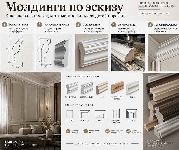
The most common reason a standard molding stops working for a project is not the ornament or the color. Far more often, the designer runs into geometry: a different projection is needed, a specific depth, an exact continuation of an existing profile, a historical cross-section, or a rhythm of relief that is not available among ready-made SKUs.
In a rendering, this problem is easy to hide. The profile can be stretched slightly, made deeper, proportions can be changed, and the closest serial item code can be left in the specification. On screen, everything will look convincing. On site, it will turn out that such a product does not exist.
That is why moldings based on a sketch should be viewed not as a “special version of an ordinary molding,” but as a separate project development. Here, the starting point is not the catalog, but a specific requirement for the profile.
The working chain looks like this:
task → sketch → cross-section → dimensions → material → straight or radius geometry → prototype → DWG/3D → APPROVED → production run → specification → order.
If this path is set up correctly, the designer receives not a beautiful abstract line, but a reproducible product that can be used throughout the entire project, reordered, and unambiguously handed over to production.
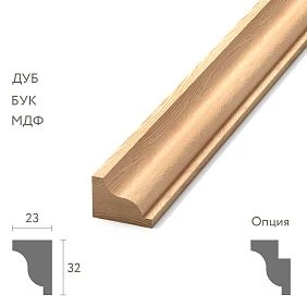
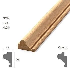
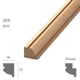
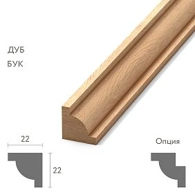
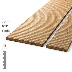
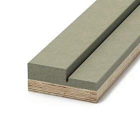
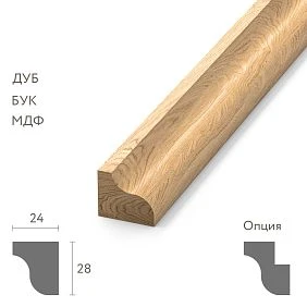
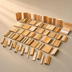
When a designer truly needs molding based on a sketch
A custom profile is justified not when you want “something of your own,” but when the standard assortment objectively does not cover the project task.
Typical cases:
- the required cross-section is not in the catalog;
- a historical profile is required;
- the new molding must continue the existing decor;
- the project requires a specific width and depth;
- a custom relief is needed;
- the profile is repeated on a large project;
- the molding is part of the project's signature architecture;
- a standard element conflicts with furniture, casing, paneling, or other geometry.
For example, a wall panel has a certain thickness, and the project molding must precisely cover its end. A stock profile may look visually similar but have a different projection. As a result, it will either fail to cover the edge of the panel or protrude too far from the wall.
Here, custom is needed not for the sake of uniqueness, but for the sake of the junction.
Another scenario is a restoration or historicizing interior. If the task is to continue an existing profile, choosing a "similar" molding from a photograph is not enough. A reproducible geometry with a specific cross-section is needed.




When custom molding is not cost-effective
A custom profile should not become an automatic solution.
If the difference from a ready-made product is only a few millimeters and does not affect the composition or components, custom development may add more complexity to the project than value.
You should not move to custom if:
- a suitable standard profile already exists;
- the molding is used on a single short section;
- the design is still constantly changing;
- the final linear footage is unknown;
- the client has not approved the composition;
- the profile can be replaced with an adjacent SKU without losing the architectural idea.
First, it's useful to check the STAVROS catalog and separately Moldings made of polyurethane.
Sometimes a project truly requires custom. Sometimes the designer simply hasn't found a ready-made solution yet.
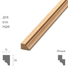
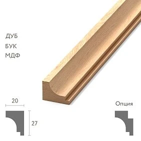
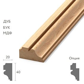
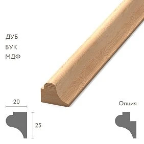
Our factory also produces:
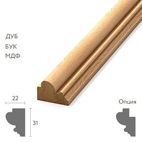
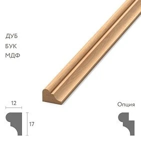
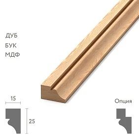
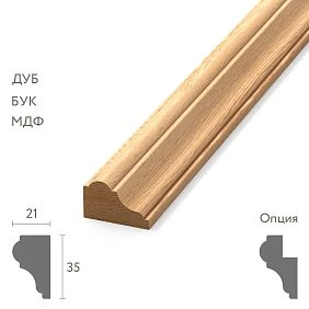
Ready-made SKU or custom molding from a sketch
The difference between a standard and a custom profile isn't just about uniqueness.
| Criterion | Standard molding | Custom molding from a sketch |
|---|---|---|
| Geometry | Fixed | Developed for the project |
| Getting started | selecting a ready-made SKU | defining the technical requirements |
| Cross-section | already determined | needs to be developed |
| Sample | finished product | prototype needed |
| DWG/3D | relate to an existing product | are created for a custom item |
| Repeat order | by SKU | based on the approved version |
| Changes | selecting a different SKU | new revision |
| Package contents | Standard | Design |
For a serial molding, the designer mainly selects.
For custom, they first design, then approve, and only then order.
This is a different responsibility.
Get Consultation
First, define the function of the profile
Before drawing the section, you need to answer the question: what exactly should this molding do?
It can work as:
- a frame profile on the wall;
- a portal surround;
- a wall panel divider;
- a furniture profile;
- platband;
- a transition between materials;
- a decorative trim;
- ceiling element;
- profile around the niche.
Function directly affects geometry.
A molding for a flat wall frame can have a small projection and work freely as a purely decorative line.
The profile around the panel must already account for the panel thickness.
Furniture molding must comply with the technological clearances of the facade.
The profile near the door casing must be compared in depth with the casing itself.
A cross-section cannot be designed in a vacuum.
What dimensions should a molding sketch contain
A sketch without dimensions is a reference.
To turn it into a technical specification, at minimum you need to define:
- total width;
- overall height;
- maximum projection;
- the mounting plane;
- front side;
- critical radii;
- nature of the relief;
- transition points between planes.
If the profile is asymmetrical, it is additionally important to show its orientation.
For example, for a 50 mm wide molding, writing “50 mm” is not enough. This figure does not convey the depth and shape.
Two profiles of the same width can produce a completely different visual effect: one will be almost flat, the second deep and shadowed.
The main document for a custom molding is not the facade.
The main document is the cross-section.
Why the front view is insufficient
A linear profile can look almost identical in a front view.
The real difference shows from the side.
It is the cross-section that reveals:
- overhang;
- the depth;
- an installation surface;
- relief;
- chamfers;
- radii;
- transitions;
- asymmetry.
Let's imagine two visually similar frames. One has a molding protruding 10 mm from the wall, the other 25 mm.
On the frontal view, the difference is almost imperceptible.
Near the door casing, it becomes decisive.
That is why a manufacturer needs a profile that can be read in section, not just a beautiful wall appearance.
How to prepare a molding cross-section
The cross-section is best prepared at a 1:1 scale and in millimeters.
It is useful to show on the drawing:
- the wall or base mounting plane;
- front side;
- dimensions;
- maximum projection;
- dimension anchoring;
- the installation direction;
- the base point;
- critical radii;
- symmetry or asymmetry.
If the profile must join with a panel, casing, or furniture part, the adjacent element should be shown alongside.
This way, the manufacturer sees not only an individual section but also the task.
It is here DWG and 3D models become a useful reference for the logic of working with real geometry.
Smooth or ornamental profile
Smooth and ornamental molding require different levels of detail.
Smooth profile
The main object is the cross-section.
It is necessary to clearly define:
- width;
- the depth;
- radii;
- chamfers;
- mounting plane.
Ornamental profile
Beyond the profile, a longitudinal logic emerges:
- repeat;
- start of the pattern;
- end;
- repeat;
- joint location;
- the behavior of the ornament in the corner.
For such a molding, it is not enough to describe only the “shape of the strip.”
You need to understand how the pattern lives along its length.
What is a molding repeat
A repeat is a recurring fragment of the ornament.
If a decorative motif repeats over a certain length, this affects the project more than it seems.
On a long wall, the repeat is almost unnoticeable.
On a short frame, it determines:
- where the pattern begins;
- where it ends;
- what falls into the corner;
- whether symmetry can be achieved;
- whether the remainder can be used.
For example, if the horizontal section is short, a random offcut may end in the middle of a sheet or scroll.
Geometrically, the length is sufficient.
Compositionally, it's not.
Therefore, the repeat must be taken into account before ordering.
How to design the joint of ornamental moulding
The joint must not accidentally cut through the main motif.
Especially if the ornament contains:
- leaves;
- Outlets;
- scrolls;
- geometric module;
- symmetrical repeat.
In the project, it is useful to show not only the length of the segment, but also the logic of alignment.
If the ornament must be centered, this affects the cutting.
Sometimes a longer offcut becomes unusable precisely because of the position of the pattern.
Therefore, when calculating a custom ornamental profile, the net linear meters almost always need to be supplemented with a map of actual cut lengths.
Straight molding and profile for a radius surface
The straight and radius scenarios cannot be combined in a single line.
If the molding is used on a curved surface, the specification must define in advance:
- radius;
- bend direction;
- arc length;
- installation location;
- internal or external nature of the curvature.
Do not assume that any custom profile can simply be bent on site.
The feasibility of a specific geometry must be confirmed by the manufacturer.
This is especially important for deep relief and rigid materials.
The radius is part of the design specification, not an installation adjustment.
Polyurethane molding based on a sketch
Polyurethane makes sense where the project requires a repeatable decorative profile, especially if relief and subsequent painting are important.
But the mere fact of choosing polyurethane does not yet mean that any geometry is automatically suitable for production.
For a custom item, the following must be confirmed separately:
- feasibility of the cross-section;
- relief;
- length;
- repeatability;
- production run;
- requirements for the sample.
At the same time, before going custom, it's worth checking ready-made Moldings made of polyurethane.
If a similar profile already exists, custom development may be unnecessary.
Wooden moulding based on a sketch
For wood, geometry is closely tied to the material.
The project must determine in advance:
- breed;
- intended finish;
- grain direction, if it is critical;
- length;
- place of use;
- surface requirements.
You can refer to Wooden moldings и Wooden trimto understand how standard profiles relate to the project brief.
If a suitable cross-section is not available, a custom profile must be coordinated taking into account the specific wood species and finish.
The same drawing in oak and in another material does not automatically mean the same manufactured product.
MDF profile per project
MDF may be appropriate where:
- a paintable profile is needed;
- natural texture is not part of the design intent;
- a uniform surface is important;
- the molding is part of a furniture or wall system.
But the material must be determined before the prototype.
Otherwise, the designer first approves the geometry in one material and then gets different physical behavior and a different surface.
A custom position must have an unambiguous record:
geometry + material + finish + revision.
Why the material cannot be changed silently after the profile is approved
The same cross-section in polyurethane, wood, and MDF does not mean the same product.
Changes:
- technology;
- surface;
- possible length;
- installation;
- finish;
- acceptable processing methods.
Therefore, changing the material is a design change.
If a custom molding was approved as one system and then, without being locked in, was switched to another material, the master sample ceases to be the reference.
It is better to issue a new revision or at least explicitly lock in the material in a separate field.
Which files to send to the manufacturer
The minimum package may include:
- PDF;
- DWG;
- 1:1 section;
- dimensions;
- the material;
- estimated length;
- total length;
- number of rooms;
- references;
- project code.
For a complex profile, the following are useful:
- 3D model;
- characteristic joints;
- position near a door or panel;
- radiused sections;
- examples of joints.
There is no need to send dozens of separate images to the manufacturer.
Better to have one package where all files belong to the same version.
Why a 3D model does not replace a section drawing
3D answers the question:
what does the profile look like in space?
DWG and the section answer:
what is the exact geometry?
These are different tasks.
In a 3D model, small scale discrepancies are easy to hide. In a render, the profile may look correct even after an arbitrary Scale.
Manufacturing requires unambiguousness.
If the 3D and DWG disagree, the manufacturer should not have to choose which one to trust.
Before launch, they must describe the same geometry.
How to assign a design code to custom positions
Until a production SKU is created, it is convenient to use a project code.
For example:
CML-01
CML-02
It should appear:
- on the DWG;
- in 3D;
- in the visualization;
- in the specification;
- in the correspondence;
- on the prototype;
- in the master sample.
Once approved, you can link:
project code → production SKU.
This way, the custom item stops being called “that wide molding from the living room.”
How to manage revisions
A custom profile almost always goes through several iterations.
For example:
CML-01_REV01
section 45 × 18 mm.
After adjustment:
CML-01_REV02
48 × 20 mm.
After approval:
CML-01_REV03_APPROVED
Only the approved version should go into production.
Names like:
final.dwg
final2.dwg
final_real.dwg
work until the first serious change.
Revision shows not only the file, but also the history of the product's development.
Why prototype is needed
You shouldn't launch a large batch of custom molding based only on the screen.
Prototype allows you to check:
- actual size;
- the depth;
- relief;
- proportions;
- edge quality;
- joint;
- surface;
- Painting;
- behavior next to neighboring elements.
This is especially important if the profile will be repeated on a large project.
A mistake in a prototype is fixed once.
The same mistake after the entire batch is released becomes systemic.
What to approve on a sample
A sample is needed not only for the phrase “like it / don't like it.”
Check specific parameters:
- width;
- the depth;
- maximum projection;
- the mounting plane;
- edge;
- relief;
- repeatability of the ornament;
- quality of the joint;
- finish.
Dimensions can be checked with a measuring tool.
But visual control is also needed: the profile must be perceived correctly from a real distance.
Sometimes the cross-section technically matches the drawing, but visually turns out to be too bulky.
It is better to discover this on a single sample.
Master sample as a reference standard
After the prototype is approved, it is useful to designate one unit as MASTER SAMPLE / APPROVED.
This is the physical control point for the batch.
The master sample can be used to compare:
- shape;
- relief;
- surface;
- edge;
- finish.
But it must be linked to a specific revision.
Otherwise, a few months later a situation may arise where the approved sample corresponds to REV02, while production is already running REV03.
A reference standard without a version loses its meaning.
How to test a molding in a real interior before a production run
A single piece of profile does not show how the entire system behaves.
If the project is significant, it is useful to assemble a test section:
- one frame;
- one internal corner;
- one outer corner;
- one joint;
- adjacency to the door casing;
- fragment near the panel.
This is how problems manifest that are not visible on a 200–300 mm sample.
For example, the profile is beautiful on its own, but too heavy for the frame.
Or the inner corner looks bad because of the relief.
Or near the door, the overhang turns out to be too large.
The test section turns an abstract sample into a real architectural situation.
Internal corner
For the inner corner, you need to check:
- cutting method;
- preservation of the relief;
- ornament alignment;
- thickness;
- visual continuation of the profile.
A smooth molding has a simpler task.
With an ornamental one, the corner may require a separate solution.
If the main motif ends up cut, it will be noticeable on every frame.
External corner
The outer corner is more visible.
The deeper and more complex the profile, the more noticeable the error.
For important areas, a separate corner prototype may be justified.
Especially if the molding works not in a flat frame, but on a portal or a protruding architectural element.
At the outer corner, the front and side geometry are visible simultaneously.
This makes any discrepancy more obvious.
Molding near the door casing
One of the best tests of a custom profile is the junction with the door.
Check:
- the depth of the casing;
- the depth of the molding;
- width;
- indent;
- top of the door;
- the termination point;
- the intersection of profiles.
If the molding protrudes beyond the casing, the junction must be intentional.
Sometimes this is part of the architecture.
Sometimes it looks like a mistake.
A front view will not show this.
A cutaway is needed.
Molding and wall panel
If a custom profile is used as a panel frame, both elements must be designed together.
The main link:
panel thickness ↔ molding depth.
If the panel protrudes more, the profile may lose its framing function.
If the molding is too deep, it begins to dominate.
Additionally, check:
- the panel edge;
- completion method;
- the transition to a smooth wall;
- angle;
- joint with the skirting board.
Custom is especially justified where a standard profile cannot properly assemble this junction.
Molding in a furniture project
Additional constraints arise for furniture:
- facade;
- panel;
- handle;
- hinge;
- gaps;
- technological fields;
- opening.
A profile can be visually perfect and at the same time physically interfere with the facade.
If a molding is part of a furniture composition, it cannot be designed solely as interior decor.
The actual furniture construction must be taken into account.
In such a situation, a custom profile becomes part of the furniture documentation.
How to determine the required production quantity
Before starting development, it is useful to have at least an approximate understanding of the order scale.
Need to know:
- total length;
- number of rooms;
- number of repeating zones;
- lengths of sections;
- estimated reserve;
- probability of reorder.
A custom profile for a single short frame and a custom profile for a hotel are different tasks.
The more repetition, the more important the master sample, revisions, and data stability.
And the more expensive a mistake made in the cross-section.
Net linear meters and purchase quantity
Net geometric length is only the first level of calculation.
Next:
geometric length → actual cut lengths → cutting → joints → remnants → reserve → purchase quantity.
For example, a project may contain 48 m of custom molding.
This does not mean that the order must be placed for exactly 48 m.
You need to know the product length and the cutting map.
Especially if the profile is ornamental.
Why the commercial length is critical
Molding exists not only as a cross-section.
It exists as a physical product of a specific length.
The commercial length affects:
- number of joints;
- Cutting;
- waste;
- logistics;
- packaging;
- number of strips.
If the project has many long verticals, a short commercial length will increase the number of joints.
If there are many small frames, long products may be more advantageous for cutting.
Therefore, the length cannot be left "for later."
It is part of the project calculation.
How to specify custom molding in the specification
A useful line might look like this:
| Field | Value |
|---|---|
| Code | CML-01 |
| Type | custom molding |
| Material | PU / wood / MDF |
| Cross-section | approved |
| Length | approved |
| DWG | REV03 |
| 3D | REV03 |
| Sample | APPROVED |
| Quantity | Calculation |
| Status | FOR PRODUCTION |
If a production SKU appears, it is added separately.
The project code can be kept: it is convenient for drawings.
What must be frozen before launching a series
Before production, changes to key parameters must be stopped.
Check:
- cross-section;
- the material;
- relief;
- repeat;
- length;
- DWG;
- 3D;
- master sample;
- quantity;
- finish;
- revision.
If any of these points is still under discussion, the profile is not fully ready for the series.
The FOR PRODUCTION status should appear only after the item can truly be reproduced without additional guesswork.
Why replacing geometry after launch is especially expensive
Changing the cross-section relative to the prototype is fairly simple: the file is changed.
After it appears:
- shape;
- tooling;
- master sample;
- production documentation;
- first batch
any major revision is no longer an edit of the sketch, but a change to the developed product.
Therefore, the cheapest changes are at the drawing stage.
The most expensive ones are after launch.
This is another reason not to rush into production before APPROVED.
How to combine custom molding and standard STAVROS products
A custom profile does not mean that the entire project has to become custom.
On the contrary, a mixed system often works better:
- main moldings — standard series;
- ceiling cornice — ready-made;
- baseboard — standard;
- decorative elements — from the catalog;
- one key profile — custom.
This way the project gets a unique detail but keeps a manageable specification.
For adjacent elements, you can use polyurethane molding, Decor for Molding и wooden decorative elements.
Custom should appear where a standard element truly does not solve the task.
First check the catalog of standard moldings
Before starting custom, it's useful to do a separate check:
- determine the required cross-section;
- compare it with standard profiles;
- check the width;
- check the depth;
- check the visual role;
- assess whether the composition can be adapted to a ready-made SKU.
If a ready-made solution fits, it is almost always simpler for reordering and specification.
If it doesn't fit — then custom becomes justified.
That is why it is better to move to development after checking standard polyurethane moldings и wooden trim.
Common mistakes when ordering a molding from a sketch
Send only the image
The manufacturer understands the overall look but not the exact geometry.
Solution: add a 1:1 cross-section and dimensions.
Scale the finished profile in 3D
The visualization shows a product that doesn't exist.
Solution: either choose another SKU or make a custom one with a new cross-section.
Not specifying the material
The prototype is made in one material, and the project is later converted to another.
Solution: lock the material before approval.
Do not maintain a revision
The old and new geometry start to coexist.
Solution: a single REV system.
Start a production run without a sample
The cross-section error repeats across the entire batch.
Solution: prototype first, then APPROVED sample.
Not checking the angle
The straight section is perfect, but the joint looks bad.
Solution: a test section.
Count only the net linear footage
Product length and cutting are not taken into account.
Solution: convert the geometry into the number of actual products.
Final checklist before launching custom molding
Before production, check:
- the standard SKU is indeed not suitable;
- the profile function is defined;
- the cross-section is drawn 1:1;
- dimensions are specified;
- the mounting plane is shown;
- material approved;
- curved sections are described separately;
- ornament and repeat are fixed;
- DWG is up to date;
- 3D matches DWG;
- Project Code assigned;
- Revision is up to date;
- prototype is manufactured;
- master sample is approved;
- inner corner is checked;
- outer corner is checked;
- junctions to doors and panels are resolved;
- total footage is calculated;
- product length accounted for;
- quantity of items determined;
- FOR PRODUCTION status assigned.
If half of the points still sound like “clarify later,” the profile is not yet ready for series production.
How to order molding from a sketch
The commercial stage begins after the geometry has ceased to be an idea and has become a technical item.
Prepare:
- sketch;
- 1:1 section;
- dimensions;
- the material;
- DWG;
- 3D, if it is needed;
- total length;
- application areas;
- project code;
- current revision.
After the technical check — prototype.
After approval — APPROVED.
Only then:
commercial estimate → quantity → batch → production → order.
For a professional handover of the project, you can use the section for designers and architects, and for discussing a specific custom task — STAVROS contacts.
If the project allows for a ready-made solution, first check the STAVROS catalog and standard moldings. If the required profile truly does not exist, then making a molding to a sketch becomes a separate, justified project task.
The final chain remains simple:
sketch → exact profile → material → prototype → APPROVED → master sample → linear meters → commercial length → batch → specification → order.
It is this sequence that turns a custom profile from a beautiful idea into a reproducible element of a working design project.