








































































Article Contents:
- Start with visually connected areas of the property
- Set a common height reference from the finished floor
- Choose common horizontals before building the frames
- Keep the levels while changing the composition of individual walls
- Align the frames with doors of different heights
- Decide where to continue the line between the hallway and the living room
- Adapt the number of frames to the width of the wall pier
- Choose the axis based on the function of the wall
- Include the built-in wardrobe in the overall grid
- Align the panels, plinth, and cornice by height
- Place switches and sockets before the final layout
- A niche can have its own composition
- Check the outer margins before the corners
- Limit the set of profiles and assign a role to each
- Assemble the overall elevation and decode the designations
- Replace conventional lines with real sections and samples
- Document exceptions as separate project rules
- How to order moldings for design interiors

From the living room, a corridor is visible: neat frames on both walls, but their upper edges are at different heights. Near the door, the line rises again, and next to the built-in wardrobe it unexpectedly breaks off. Each elevation, viewed on its own, looks convincing. The inconsistency becomes noticeable only when the spaces are perceived together.
Mouldings for designed interiors are selected and placed with such relationships in mind. Before drawing individual frames, the overall horizontals, main axes and boundaries of zones with different rules are determined. Then the living room, passages, niches and furniture gain a coherent structure while retaining their own proportions.
This does not require making all walls identical. What is needed is a clear system: from which mark to measure height, which line to continue through an opening, where to change the rhythm and how to document the chosen solution. Profile, sample and purchase become the next steps after this coordination.
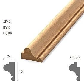
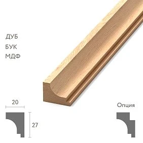
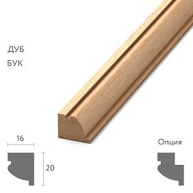
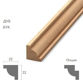
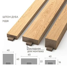
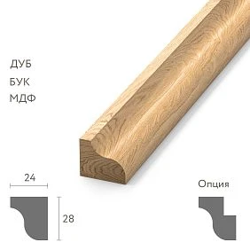
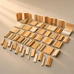
Start with the visually connected zones of the project
The first working material can be a plan with marked sightlines. It shows which walls a person views simultaneously: the living room and corridor through a wide opening, two sides of the hall, the pier next to the kitchen and the adjoining wardrobe. It is in these combinations that accidental shifts of horizontals are most noticeable.
Rooms behind a closing door may have a more independent composition. An open enfilade, by contrast, requires checking several rooms at once. Therefore, the boundary of the common system does not always coincide with the boundary of a room in the room schedule: it is also determined by how the space is perceived.
At this stage, fixed elements are recorded: the location of openings, windows, furniture and ceiling level changes. For each, it is noted whether its dimensions are approved. For example, a not-yet-chosen door casing height should not imperceptibly become the final base for all frames.
Such an overview helps distribute mouldings for designers and architects according to project tasks. First, a connected zone and its main lines are identified, then specific walls are addressed. This reduces the number of situations where, after approving an adjacent room, the already completed composition of the living room has to be rebuilt.




Set a common height datum from the finished floor
It is convenient to take the approved finished floor level of the main zone as the starting datum. It is important to link it to the project's overall system and show how levels in other rooms are measured from it. The subfloor and the finished covering may be at different heights.
If the finished floors of the rooms differ, the same distance from each local floor will not create a common horizontal line. Consider a hypothetical example: the line should run at a level of 1100 mm relative to the accepted zero, while the corridor floor is 20 mm higher than the living room floor.
| Room | Finished floor level relative to the common zero | Height of the common line above the local floor |
|---|---|---|
| Living room | 0 мм | 1100 мм |
| Corridor | +20 mm | 1080 мм |
If you measure 1100 mm from the floor in both rooms, you get a 20 mm step. The numbers here illustrate the calculation, not the recommended height of the decorative band.
The documentation specifies the source of the elevation reference and the units of measurement. On site, levels are transferred from an agreed base, checking their compliance with the design. Then different contractors do not create their own "zero" at each wall and do not try to hide the discrepancy with a slanted molding line.
Our factory also produces:
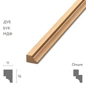
Choose common horizontal lines before building the frames
Not all horizontal elements have to be at the same height. Usually several significant lines are chosen: the top of the lower panels, the top of the wall frames, the decorative band, the lower edge of the cornice. Their number depends on the composition, and each line gets a certain scope.
Before assigning levels, compare doors, windows, the ceiling, and built-in furniture. For example, the top of a wall panel may support a furniture frieze, while the upper frame maintains an equal margin under the cornice in a related group of rooms. At the same time, the windowsill does not have to become a base just because it forms a noticeable horizontal line.
For each line, it is important to determine which part of the profile the level refers to: the lower edge, the upper edge, or the centerline of the section. If one specialist sets the dimension to the centerline and another to the outer edge, even identical numbers will give a different result.
After choosing the actual section, the preliminary levels are checked again. The width of the profile affects the free margin, although the centerline itself may remain in place. Therefore Moldings made of polyurethane they are included in the check before the final approval of dimensions, without leaving an abstract thin line on the working layouts.
Get Consultation
Maintain the levels while changing the composition of individual walls
The common upper boundary of the frames does not require the same number of fields. In the living room, you can place three frames; in the hallway, one elongated one; on a short wall section, a small vertical one. The system remains recognizable thanks to the common marks, the character of the profile, and the coordinated intervals.
It is useful to separate fixed and variable parameters. The fixed ones within the selected zone may include the upper and lower boundaries of the composition, the profile type, and the principle of indents. The variable ones include the width of the frames, the number of modules, and the position of the central axis. Then adapting the wall becomes manageable.
For example, a narrow wall section near a door should not be filled with a reduced copy of the three-part composition of a large wall. After such scaling, the frames become cramped, and the gaps lose their meaning. One calm frame can better support the overall horizontal line of the neighboring room.
When selecting, . Clear lines, created using modern technologies, emphasize the strict aesthetics of the room. Each decorative element harmoniously fits into the overall concept, creating a sense of order and thoughtfulness. additional elements are also subject to this rule. Ornament may appear only in the main zone, while secondary walls retain the same profile without overlays. Unity is created by repeating the chosen features, not by necessarily duplicating every detail.
Align the frames with doors of different heights
The door portal often becomes the main reference point of the wall. You need to decide how the top of the frames relates to it: whether it coincides with the outer edge of the casing, is higher, or is lower. It is the visible elements of the completed opening that are compared, not alternately the height of the leaf, the frame, and the casing.
If there are doors of different heights nearby, several approaches are possible.
| Approach | When to consider it | What to fix |
|---|---|---|
| Common horizontal alignment of frames | Walls are perceived simultaneously | Its relationship to each portal |
| Local alignment to doors | The compositions are sufficiently self-contained | The scope of each rule |
| A separate transition zone | There is an architectural boundary between different systems | Where one layout ends and another begins |
The choice is made based on the overall elevation and views through the openings. Automatically raising all frames to the tallest door or adjusting each to the nearest one is equally risky for the composition: both solutions require verification in the specific space.
The situation is especially inconvenient when in one room the height is measured to the top of the casing, while in the adjacent one it is measured to the door leaf. Visually, this looks like a random mistake. That is why the drawing specifies the exact reference boundary instead of settling for the phrase "at the top of the door."
Decide where to continue the line between the hallway and the living room
Through a wide open opening, the horizontal line may visually continue even if the profile is physically interrupted in the door area. For such a solution, a coordinated elevation is maintained and the view from the main vantage points is checked. The viewer should read the connection by the actual edges of the profile, not only by the conventional axes of the drawing.
Another option is to start an independent composition beyond the portal. This is appropriate when the ceiling height, the character of the room, or the finish system changes. Then the opening itself becomes a clear boundary at which the previous line ends.
Problems arise in the intermediate solution: the frames look almost connected but diverge slightly without any visible reason. In that case, one should either restore the exact continuation or more clearly mark the transition. A small random offset is often more noticeable than a deliberately different composition.
If the profile must continuously wrap around a reveal or pass through a portal, a separate detail with actual cross-sections is required. The visual connection of two walls does not by itself mean that the molding must be run across all intermediate surfaces. Physical continuation is chosen only where it supports the architecture and is feasible within the adopted construction.
Adapt the number of frames to the width of the wall section
It is convenient to start the layout from the available wall width after accounting for openings and furniture. Then the outer margins, gaps, and number of frames are assigned. The dimensions should have a clear meaning: for example, the width of a frame along the outer edges of the molding and the clear gap between adjacent frames.
In the illustrative example, the wall is 3600 mm wide. 200 mm is left at each edge, and between the three frames there are two gaps of 160 mm each. The frames account for 3600 − 400 − 320 = 2880 mm, that is, 960 mm each. This is a check of the chosen layout, not a universal proportion.
On a wall section 1100 mm wide, with the same outer margins, one frame 700 mm wide will fit. The preserved top and bottom elevations will link it to the large wall, although the horizontal dimensions will be different.
After calculation, the actual sections and internal field are checked. An ornament, painting, or mirror must fit within the frame with the specified margins. If the result looks cramped, the number of modules or the margin principle is changed. Simply scaling down the entire large composition along with the gaps usually does not meet the needs of a narrow area.
Choose the axis based on the wall's function
The geometric center of the wall does not always coincide with the center of the perceived composition. In a bedroom, the main reference point may be the bed; in a living room, it may be the fireplace, mirror, or TV group. A doorway and a built-in wardrobe further alter the available field.
Therefore, the leading axis is chosen first and its origin is explained. If the frame is tied to the bed, its center is aligned with the agreed position of the bed. Dividing the full length of the wall in half here can give a misleading reference point, especially when a wardrobe is on one side.
For a connected group of rooms, the axes do not necessarily coincide physically. What matters is that the transition between them is clear: the portal organizes the entrance, and beyond it the composition follows its own functional zone. Trying to subordinate all walls to one randomly chosen vertical often creates awkward residual margins.
On the elevation, the axes of the furniture and decor are shown simultaneously. If an item has not yet been approved, its position is marked as requiring coordination. Otherwise, a change in the width of the headboard or fireplace after the moldings are ordered will force the frames to be revised. Deciding on the axis early makes it possible to distinguish a furniture change that affects the decor from a replacement that does not affect the composition.
Include the built-in wardrobe in the overall grid
A floor-to-ceiling wardrobe has its own horizontals and verticals: the top frieze, the division of the fronts, the plinth, and the side panels. These are compared with the wall molding, baseboard, and cornice before the furniture is released for production. Matching heights on two separate drawings still need to be verified in a common reference system.
Decide in advance where the wall line ends. It may stop before the furniture with an agreed margin, continue onto a fixed side panel, or be extended in the pattern of the fronts. For each option, the installation planes and actual protrusions of the parts are checked.
If the line continues onto an opening front, the gaps and movement of the door are taken into account. A visual continuation does not require covering the moving joint with molding. The furniture and wall parts are shown as separate elements with coordinated joining.
When used in the furniture part Wooden moldings and trim, and on the wall — a polyurethane profile, equal width is not enough. Compare cross-sections, projection, and finish on a trial transition. Different materials can be combined compositionally, but the specific joint must be confirmed, not assumed to match based on similar photographs.
Align panels, baseboard, and cornice by height
The top of the wall panel becomes an additional reference line within the overall height measurement. The molding can mark this boundary, sit above it, or form an independent frame. It is important to record the chosen relationship so that two nearly coinciding horizontal lines do not appear near the panel.
The lower part of the wall is assessed from the finished floor through the baseboard and the free field to the frame. The upper part — from the frame through the remaining wall surface to the cornice. This way, the proportions of the entire height are visible, not just the decorative rectangle.
Polyurethane moldings and cornices are compared by cross-section and visual expressiveness. A deep cornice can highlight the top of the wall more strongly, even if its color matches the background. When selecting ceiling decoration made of polyurethane check the actual lower edge of the cornice in the installed position.
With different ceiling heights, it is impossible to automatically preserve both the common top of the frames and the same field to the cornice. A priority must be chosen: continuing the horizontal line or a separate composition for the room. This choice is recorded in the zone rules. Fitting each frame to the nearest ceiling section without an overall logic turns the noticeable field under the cornice into a random remainder.
Place switches and sockets before the final layout
On the general elevation, engineering points must appear before the frames are approved. Show the external dimensions of switch and socket frames, not just the nominal centers. For a block of several mechanisms, this is especially important: its actual width may cross the molding even with a formally correct axis alignment.
Other elements are also checked: thermostats, control panels, ventilation grilles, and access to service hatches. The decorative line must take into account their purpose and usability. A cover hidden behind an ornament does not become more convenient just because it is barely visible in the visualization.
If a switch falls on the profile, consider changing the frame width, shifting the vertical, or redistributing the field. The possibility of moving the engineering point itself is agreed with the responsible specialist and reflected in the relevant project. Electrical work already completed cannot be considered a freely movable element of the sketch.
After a change, the entire related composition is checked. Shifting one vertical can disrupt symmetry relative to the furniture or change the gap to the neighboring frame. Therefore, the decision is made on the overall elevation, and then all affected drawings are updated. A small local edit must remain consistent with the other alignments.
A niche may have its own composition
A niche simultaneously belongs to the main wall and forms a separate volume. Its treatment may continue the common horizontals, follow a local axis, or become an independent accent. The chosen option is shown on the overall elevation together with the depth and side surfaces.
For example, a niche for a sculpture may receive its own framing, while a long shallow niche may support the room's decorative band. In the first case, the center of the object and the free field around it are important. In the second, the alignment of lines when viewed along the wall matters.
A local system must not mean a new unfixed zero. The niche's elevation marks are tied to the common datum, and its horizontal dimensions to a clear axis or the edge of the opening. Then it can be positioned precisely, even if its internal pattern differs from the neighboring frames.
Depth requires separate verification: the profile on the front plane and the profile inside the niche may cast different shadows. If lighting is provided, the mockup or sample is examined under the appropriate conditions. The connection is ensured by common reference lines, while volume and light are checked as features of a specific area, without trying to solve everything with a single flat diagram.
Check the edge fields before the corners
A layout built from the center of the wall may leave too narrow an area near the corner. On a separate elevation it looks like a small remainder, but in the room two neighboring frames end up compressed on both sides of the corner. Therefore, the edge fields are checked on adjacent walls simultaneously.
It is necessary to distinguish between closed frames on a plane and a continuous band wrapping around a room. For frames, the offsets from the corner and the ratio of the outer modules matter. For the band, the geometry of the joint, the continuation of the profile, and the matching height on the opposite wall matter.
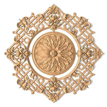
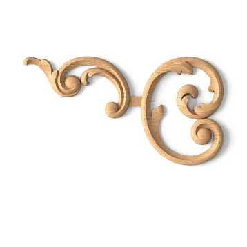
If ready-made elements from the decorative section for moldingsare used, check their purpose and compatibility with the selected profile. The corner of a flat decorative frame and the turn between two walls are different nodes. A detail that matches in style does not automatically become a solution for any corner.
If the remaining field is inconvenient, it is better to revise the neighboring modules before cutting. One cannot count on a small decorative insert necessarily hiding a rhythm error. It takes up space itself and can make a tight area even more noticeable. A trial corner helps confirm the decision after the overall layout check.
Limit the set of profiles and assign a role to each one
A single object does not have to be finished with only one molding. Main walls, secondary rooms, and small accents may require different scales. It is easier to manage a limited set of profiles with clear purposes than to choose a new profile for each frame.
Below is an example of conventional project designations, not manufacturer SKUs.
| Project code | Profile role | Application rule |
|---|---|---|
| P-1 | Primary wall frames | Used in a coordinated group of shared horizontals |
| P-2 | Secondary zones | Applied within the designated rooms |
| P-3 | Small accent fields | Receives local dimensions and individual references |
Each code is then assigned a full article number, material, size variant, and finish. Such a schedule defines the application rules; the number of strips is calculated separately.
On a line that should be perceived as continuous, a single profile and coordinated finish are usually maintained. Replacing it midway requires a meaningful transition. When selecting moldings from polyurethane check the material of the specific item rather than relying only on the name of the catalog section.
Similar widths of two profiles do not make them interchangeable. Different depth and groove shape change the shadow, so a substitution may become noticeable precisely at the point where the shared horizontal continues.
Assemble the general elevation and decode the designations
For a connected zone, a general coordination elevation is useful: the walls of the living room, passage, corridor, and built-in furniture are shown side by side at the same scale. Openings and turns are clearly marked, and common reference marks can be traced without switching between individual beautiful images.
The elevation is linked to the plan through wall numbers and viewing directions. This helps to understand where two lines continue in space and where they merely happen to be next to each other on the sheet. Depth features are shown with additional sections.
The legend explains the meaning of each code. For example:
| Designation | Value | What should be indicated on the drawing |
|---|---|---|
| U-1 | Top of lower frames | Mark relative to the common zero and the exact edge of the profile |
| U-2 | Top of upper frames | Marking and list of application zones |
| O-1 | Door portal axis | Alignment to approved opening dimensions |
| P-1 | main profile | Link to the article number in the profile schedule |
Specific numerical values are assigned in the project. Letter codes alone are not sufficient marking for installation.
Such a system can be handed over to another specialist without verbally explaining each wall. Materials STAVROS for designers and architects are used within the already defined roles and alignments, maintaining a consistent meaning of the designations across all documents.
Replace the conditional lines with actual sections and samples
After building the preliminary grid, the selected profiles with actual dimensions are entered into it. Then the free fields, protrusions, and junctions are checked again. This cycle is important: the architectural scheme determines the choice, and the actual product refines its geometry.
В catalogs, drawings, and models of STAVROS They select materials for specific product codes, checking the availability of the required format. Working DWG files and the 3D model must use the same dimensional version. A conditional profile is acceptable in an early sketch, but after the product is chosen it is replaced or correctly rebuilt.
Images are also compared separately through the openings: lines agreed on in the elevation drawing may be perceived differently due to wall depth and lighting. The 3D model helps verify this view, while samples of moldings and decor — the actual expressiveness of the section.
The sample is placed in the design area and viewed from a normal distance. Deep relief can visually make a correctly sized frame look heavier. If the product code changes after fitting, the model, working drawings, and profile schedule are updated. The previous section must not remain in one of the documents unnoticed by the specifier or installer.
Document exceptions as separate project rules
A stair hall, double-height space, formal hall, or room with a low ceiling may require its own grid. A common system is useful as long as it helps the architecture. An exception is justified when its reason and scope of application are explained.
For example, in a separate high living room, the upper frames may follow a different level than in the corridor. Then the portal marks the transition, and in the documents both zones receive different rules. This is clearer than randomly changing the height at each successive wall section.
Exceptions are recorded in the same place as the main provisions: the room, the affected line, the selected profile, and the relationship to neighboring zones are indicated. Separate notes in correspondence are easily lost, especially when several specialists are working on different parts of the project.
When a decision changes, a new version of the relevant drawings and schedules is assigned. They check which neighboring walls it affects and pass the current set to the contractors. Changes to the door, ceiling, and built-in furniture are especially important: they can shift the main reference points of an already approved grid. Rechecking the related zones helps preserve the system even when a separate part of the project changes.
How to order moldings for designed interiors
Meterage is calculated after the layout, actual profiles, and main junctions are approved. First, the dimensions of individual parts are obtained, then a cutting map is drawn up based on the available commercial lengths. The total sum of frame perimeters does not yet indicate how many whole strips will be required for delivery.
To buy polyurethane moldings for frames, full article numbers, size versions, and quantities are transferred to the request. Compatible corner and connecting decor is accounted for separately. The reserve is assigned taking into account cutting and the complexity of junctions, while keeping its breakdown by item.
Project codes are linked to rooms so that identical products can be distributed across the site without changing the meaning of the specification. The finish and finishing requirements are recorded for the relevant contractor. Availability and delivery times are clarified for the entire order composition; the availability of the main profile does not confirm the readiness of all additional elements.
Before being handed over for work, the overall height reference, the profile edge for each mark, axes, transitions, and the documentation version are checked. As a result, a kit is purchased for a specific wall system. The installer receives clear references, the furniture maker receives approved junctions, and the designer preserves the chosen relationship of rooms from the elevation drawing to the finished interior.