Article Contents:
- MLD-051 30×16 mm: what profile is actually being considered
- Why 30 mm is responsible for possible blocking
- Why 16 mm is sometimes more important than 30 mm
- 1. Panel edge
- 2. Nearest edge of the LED profile
- 3. Width of the LED profile
- 4. Installation depth
- 5. Diffuser position
- 6. Light direction
- 7. MLD-051 base
- Scenario 1. 24 mm measured to the near edge of the LED
- Scenario 2. 24 mm measured to the center of the LED
- Scenario 3. LED is placed outside the decorative frame
- Scenario 4. Molding is mounted on the wall around the panel
- Diagram 1. MLD-051 is in front of the LED profile
- Scheme 2. MLD-051 is behind the light line
- Scheme 3. LED is located between the panel and the molding
- Scheme 4. MLD-051 becomes the outer boundary of the entire composition
- Why a paper strip is not suitable
- What the mock-up should imitate
- How to check
- Top side
- Bottom side
- Verticals
- Angle
- MDF
- Beech and oak
- MLD-051 ends above the baseboard
- Frame comes to the baseboard
- LED goes between them
- Error 1. Treating 30−24=6 as the final answer
- Error 2. Making a paper template
- Error 3. Checking only during the day
- Error 4. Buying material before checking corners
- Error 5. Strengthen LED instead of fixing geometry
- What is the size of MLD-051?
- What is the width of MLD-051?
- How much does MLD-051 protrude?
- What is the length of MLD-051 made of MDF?
- What is the length of beech and oak MLD-051?
- Can MLD-051 be placed next to an LED strip?
- Will MLD-051 cover the LED at a distance of 24 mm?
- Why is 30−24=6 mm not enough?
- How to make a mockup of MLD-051?
- Why is a paper template not enough?
- Do I need to move the LED profile?
- What gap is needed between the molding and the LED?
- What to choose — MDF, beech, or oak?
- When is MDF more convenient?
- When is oak particularly interesting?
- How many planks are needed for the frame?
- Can the joint be left on the horizontal?
- Why are 2450 mm important for material selection?
- How much does MLD-051 made of MDF cost now?
- How much does beech MLD-051 cost?
- How much does oak MLD-051 cost?
- Where can I buy wooden moldings?
- Where can I buy MDF molding?
- Where can I buy MLD-051?
- How can I order MLD-051?
- How to check the current price?
- Do I need to check all four sides of the panel?
- When is it too early to buy MLD-051?
- When can MLD-051 already be ordered?
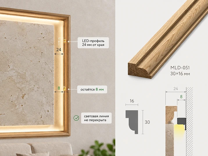
In the evening, we turned off the main light, leaving only the contour backlight of the panel, and placed a small block measuring approximately 30×16 mm against the edge. The light did not disappear, but changed immediately: where there used to be a soft light border, a harder shadow appeared. It is this simple test, better than any render, that shows whether it is worth adding MLD-051 to an already working LED backlight.
The problem in this project is not whether the molding itself is beautiful. The panel is already assembled, the backlight is already working, and its effect is satisfactory. Therefore, the wooden frame must adapt to the existing light unit, not the other way around.
Based on the original geometry, the LED profile is located 24 mm from the edge of the panel. The face width of MLD-051 is 30 mm. If both values are measured from the same line and the molding is installed inside the panel, we get:
30 − 24 = 6 mm.
Formally, the profile extends six millimeters beyond the line where the LED unit begins.
But these six millimeters are not enough to declare: "MLD-051 will cover the backlight." You need to know what exactly is at the 24 mm mark — the edge of the aluminum profile, the center of the strip, the edge of the diffuser, or the visible light gap. Equally important is the direction of the light: it can go into the room, reflect off the wall, or work as hidden contour glow.
Therefore, the correct decision here is made not with a tape measure in one plane, but based on the cross-section and the evening mock-up of 30×16 mm.
MLD-051 30×16 mm: which profile is actually being considered
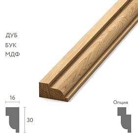
The current MLD-051 card confirms three standard versions:
| Material | Size | Length | Price at the time of check |
|---|---|---|---|
| MDF | 30×16 mm | 2600 мм | 670 ₽ |
| Beech | 30×16 mm | 2400 мм | 1 870 ₽ |
| Oak | 30×16 mm | 2400 мм | 2 720 ₽ |
For the backlight theme, two cross-section sizes are important:
-
A = 30 mm — profile width across the face;
-
C = 16 mm — protrusion relative to the base.
If the assembly fits after the mockup, you can buy the wooden molding MLD-051 30×16 mm in the required material.




Why 30 mm accounts for possible overlap
If the frame is installed from the edge of the panel inward, this width takes up part of the decorative field.
With LED at the 24 mm mark, a 30 mm wide profile potentially falls into the same zone.
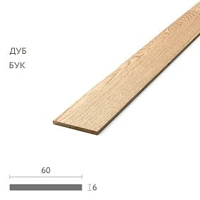
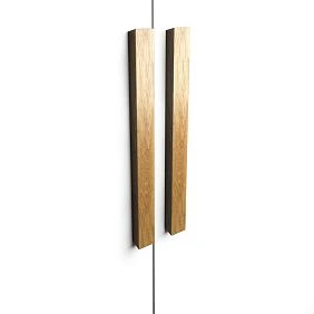
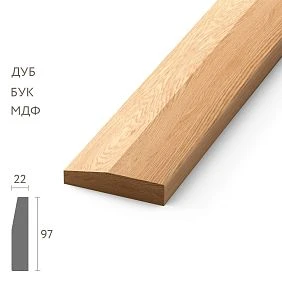
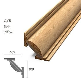
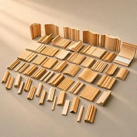
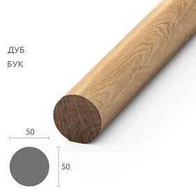
Our factory also produces:
Why 16 mm is sometimes more important than 30 mm
Light spreads volumetrically. Even if the light source remains exposed according to the plan, a profile protruding by 16 mm can act as a visor and change the light cone.
It can:
-
block direct view of the source;
-
make the light softer;
-
create a pronounced shadow;
-
reduce the visible light strip;
-
on the contrary, improve hidden reflected glow.
That is why a 30 mm wide paper strip does not replace a volumetric mockup.
Get Consultation
Buying a wooden molding after LED installation: which dimensions to re-measure
Before purchasing the batch, you need to re-measure the already assembled unit.
1. Edge of the panel
This is the baseline.
It is necessary to determine from which physical boundary the 24 mm measurement starts.
2. Nearest edge of the LED profile
If 24 mm is measured to the center of the aluminum profile, the situation is one. If to its nearest edge, it's another.
3. Width of the LED profile
The light unit itself also has dimensions.
It cannot be considered an infinitely thin line.
4. Installation depth
The profile can be recessed, flush, or protruding.
5. Position of the diffuser
The visible light surface may not be where the tape itself is.
6. Direction of light
You need to understand where the light beam actually goes.
7. Base of MLD-051
The molding can be attached to a panel, wall, or separate backing. This changes the relative position of all elements.
If you want buy wooden moldings, cornices, and baseboards, this measurement is better done before choosing the material and quantity.
Why the difference of 30 and 24 mm does not give a ready answer
Mathematics:
30 − 24 = 6 mm.
But it only works when the bases match.
Scenario 1. 24 mm measured to the near edge of the LED
Then MLD-051 physically enters the profile area if installed inside the panel from the same edge.
Scenario 2. 24 mm measured to the center of the LED
The actual intersection already depends on the width of the profile itself.
Scenario 3. LED is placed outside the decorative frame
Then 30 mm may not overlap the source at all.
Scenario 4. Molding is mounted on the wall around the panel
It gets a different base plane, and a simple 30/24 comparison no longer describes the joint.
Four schemes of MLD-051 and the light line
Here it's more useful to think not in terms of "fits / doesn't fit," but in terms of schemes.
Scheme 1. MLD-051 is placed in front of the LED profile
The molding is closer to the observer.
In this case, the 16-millimeter protrusion can block direct view of the source.
This is useful if the goal is to hide the strip itself and leave only reflected glow.
It's bad if the design is built on a visible bright line.
Scheme 2. MLD-051 is placed behind the light line
The LED remains closer to the edge, the molding is deeper.
Then the light can separate the frame from the panel or wall.
This option gives a pronounced decorative contour, but requires sufficient space.
Scheme 3. LED is located between the panel and the molding
The light gap becomes an independent intermediate element.
Here, the 30 mm width and 16 mm protrusion are especially important: the wood must not accidentally pinch the light strip.
Scheme 4. MLD-051 becomes the outer boundary of the entire composition
LED works inside the panel, and the molding frames the finished lighting system from the outside.
Sometimes this is the safest option because it does not interfere with the existing light source.
When the 16 mm protrusion creates a beautiful deep shadow
MLD-051 does not always interfere with the backlighting. Sometimes it makes it better.
If the source is completely hidden and the viewer sees only reflected light, the protruding profile can create a deeper chiaroscuro.
A good result is achieved when:
-
the diode itself is not visible;
-
the reflection is even;
-
the shadow from the molding repeats along the entire contour;
-
there are no sharp brightness drops in the corners;
-
the frame looks like part of the architecture, not a random obstacle.
Then buy wooden decorative molding it makes sense precisely for the combination of profile and light.
When MLD-051 starts to "eat up" the backlight
The opposite scenario — the LED is directed straight into the room, and the molding stands in front of the diffuser.
Then the 16 mm protrusion can:
-
close part of the light surface;
-
sharply reduce the light exit angle;
-
create a dark stripe;
-
make brightness uneven;
-
especially darken the corners.
A bad strategy is to immediately install a more powerful strip.
First, the geometry is corrected. If the light is physically blocked, increasing power only raises the brightness of the remaining open part and can make the contrast even more noticeable.
Why you should check specifically in the evening
During the day, the panel often looks great even with incorrect light geometry.
In the evening, the following become visible:
-
hard shadow edges;
-
dark spots in corners;
-
unevenness;
-
too narrow light strip;
-
glare on the molding;
-
visible light source points.
It is useful to check in several modes:
-
LED only;
-
LED + ceiling light;
-
LED with side interior light;
-
front point;
-
side viewing point.
The cheapest test is a 30×16 mm volumetric mock-up.
You don't need to buy the entire contour to understand whether MLD-051 works.
It's enough to make a piece 300–500 mm long.
Why a paper strip is not suitable
It only shows the 30 mm width.
But the light strongly depends on the 16 mm protrusion.
What the mock-up should imitate
-
30 mm width;
-
protrusion 16 mm;
-
the actual assembly line.
How to check
Temporarily attach the mockup to one straight side of the panel and turn on the backlight.
Then take a photo:
-
straight on;
-
at an angle;
-
in the evening;
-
with the main light;
-
without it.
If the effect is satisfactory on a straight section, proceed to the corners.
The corners of the panel are checked separately
Even if one horizontal line looks perfect, a 90° angle can produce a different light pattern.
Top side
Light is usually perceived against the background of the ceiling and wall.
Bottom side
May intersect with furniture, baseboard, or floor.
Verticals
More noticeable when viewed from the side.
Angle
In the corner, the direction of two LED sections changes, and two molding segments come together.
Here, the risk of local darkening is higher.
MDF MLD-051: when it is convenient to combine it with a painted panel
MDF has a standard length of 2600 mm and the lowest current price.
If the panel is painted with opaque enamel, you can buy an MDF molding and make a frame in the color:
-
panel;
-
walls;
-
furniture;
-
or a contrasting tone.
The advantage in the lighting project is that you can relatively inexpensively make a test fragment and check the color in the evening.
Light can noticeably change the perception of even neutral enamel.
Oak MLD-051 next to warm lighting
Oak is especially interesting under warm LED lighting.
Warm light can more strongly reveal:
-
wood grain pattern;
-
tinting;
-
profile relief;
-
shadow depth.
But the result depends on the specific light temperature, finish, and oak shade.
Therefore, oak is better assessed with a real sample in the evening, rather than choosing only by the daytime product card.
The cost of a mistake here is higher: a standard oak plank currently costs 2,720 ₽.
Beech MLD-051 under enamel
Beech can be chosen when you want a wooden profile specifically, but the natural texture is not planned to be left visible.
In this variant, the emphasis shifts to:
-
cross-section shape;
-
quality of preparation;
-
color;
-
interaction with LED.
But even here, the 30×16 mm geometry is checked first. The material will not fix an unsuccessful frame position relative to the light source.
2600 or 2400 mm: the quantity is counted only after the light is approved
It is not yet known where the frame will run, so it is too early to count the slats.
For each side, the finished length is recorded.
MDF (740–760 kg/m³, emission class E1/E0) provides ideal geometry, uniformity, and better base for enamel: high adhesion, smooth surface, absence of knots and cracks.
Standard is 2600 mm.
Beech and oak
Standard is 2400 mm.
These 200 mm sometimes completely change the cutting layout.
Let's imagine a panel vertical of 2450 mm.
For MDF:
2450 < 2600 — the part can be obtained as a single piece.
For solid wood:
2450 > 2400 — one standard slat no longer covers the side.
That is, the total perimeter cannot simply be divided by the length of the stick.
Why does the panel perimeter give an incorrect count
Let the panel have a nominal size of 2450×1600 mm.
Perimeter:
2450 × 2 + 1600 × 2 = 8100 mm.
If you simply divide 8100 by 2600:
8100 / 2600 = 3.12 → 4 strips.
But you need to check the cutting of individual sides.
Two verticals of 2450 mm already require two separate strips.
Two horizontals of 1600 mm remain.
From the third 2600-mm strip, one 1600 horizontal fits, leaving 1000 — not enough for the second horizontal.
So, a fourth strip is still needed.
For a 2400 mm array, 2450 verticals cannot be made as whole standard parts at all. Therefore, the scheme changes more significantly.
Price of MLD-051: first a mockup, then the material
For the current card:
-
MDF — 670 ₽;
-
beech — 1,870 ₽;
-
oak — 2,720 ₽.
If the contour requires several strips, an error in geometry becomes noticeable in the budget.
It is especially pointless to buy an oak batch and then find out that the 16-mm protrusion blocks the light line.
Is it necessary to relocate an already installed LED profile
Not automatically.
If the light already works well, it is logical to first try to preserve it.
Possible options:
-
shift the wooden frame;
-
install the molding outside the contour;
-
choose a narrower profile;
-
change the width of the smooth strip;
-
refuse MLD-051 on one of the sides;
-
only then consider reworking the LED.
Reworking a working backlight for the sake of a decorative frame must have a clear design reason.
When it's better to choose a different molding
If a 30×16 mm layout shows that MLD-051 interferes too much with the light, you don't need to force this particular profile to work.
You can go back to the section buy wooden moldings, cornices, and baseboards and look for an option:
-
already on the face;
-
less by protrusion;
-
with a different relief;
-
better suited in length.
The bottom line of the panel and the plinth
If the light contour also runs along the bottom, another adjacent element appears — the floor plinth.
Before choosing it, you can open to buy wooden baseboard.
You need to decide what happens at the bottom.
MLD-051 ends above the plinth
Then a separate wall zone remains.
The frame reaches the plinth
Need to think through the joint of two profiles.
LED goes between them
A third horizontal line appears.
If in one place the baseboard, MLD-051, and light gap are read simultaneously, the node easily becomes overloaded.
Errors in the MLD-051 + LED project
Error 1. Considering 30−24=6 as the final answer
Reason: both numbers seem comparable.
Consequence: the width and position of the LED profile are forgotten.
How to avoid: take a section from one base.
Error 2. Making a paper template
Reason: only the width is checked.
Consequence: the shadow from the 16-millimeter protrusion is not visible.
How to avoid: a volumetric mockup.
Mistake 3. Check only during the day
Reason: the geometry seems neat.
Consequence: light gaps appear in the evening.
How to avoid: a nighttime check.
Mistake 4. Buy material before checking the corners
Reason: the straight section already looks good.
Consequence: the light is much darker in the corners.
How to avoid: mock up at least one corner.
Mistake 5. Increase LED brightness instead of fixing geometry
Reason: it seems that there is simply not enough light.
Consequence: the open part becomes brighter, but the shadow remains.
How to avoid: first the position of the profile.
When MLD-051 does not need to be purchased yet
The purchase should be postponed if:
-
the 24 mm distance is measured from an unclear point;
-
the width of the LED profile is unknown;
-
the direction of light is not defined;
-
the light was not checked in the evening;
-
MLD-051 was only seen in photos;
-
there is no volumetric mockup 30×16 mm;
-
panel corners are not verified;
-
material is chosen before geometry approval;
-
quantity is already calculated for one perimeter.
When MLD-051 can already be ordered
Order becomes justified when:
-
LED is fully installed;
-
light effect is accepted;
-
all dimensions are taken from one base;
-
layout made 30×16 mm;
-
at least one horizontal and one vertical checked;
-
angle checked;
-
position of MLD-051 approved;
-
whether MDF, beech, or oak is selected;
-
finish selected;
-
cutting map 2600/2400 built;
-
quantity calculated;
-
price and availability rechecked.
After that, you can order MLD-051 for backlit panel.
Example of a specification:
MLD-051 / 30×16 mm / MDF 2600 or beech/oak 2400 / panel ___×___ / LED profile located ___ mm from edge based on ___ / MLD-051 installation diagram ___ / final part lengths ___ / material ___ / finish ___ / quantity ___.
Where to check material and delivery
If the project involves more than just the frame, you can open Wood and MDF moldings.
Before finishing — materials and quality of wooden moldings.
Before ordering long planks — delivery conditions for wooden moldings.
Result: first turn off the main light and apply the 30×16 mm mockup
This article has no universal answer like "MLD-051 will cover the LED" or "it won't."
There is a specific check.
If 24 mm and 30 mm are measured from the same base, the molding potentially enters the light profile zone by 6 mm.
But the result depends on the three-dimensional node.
30 mm determine the strip that the frame occupies.
16 mm determine how much it protrudes and what shadow it creates.
The most sensible order:
real LED → evening check → MLD-051 mockup 30×16 → angle → frame position selection → material → cutting → purchase.
If after the mockup the light becomes deeper and cleaner, MLD-051 works as part of the composition.
If the light line narrows, falls into the corners, or turns into a rigid dark gap, you should not buy an oak or beech batch hoping that the finish will fix the geometry.
First, change the position of the profile or choose a more compact molding.
FAQ
What is the size of MLD-051?
30×16 mm.
What is the width of MLD-051?
30 mm by parameter A.
How much does MLD-051 protrude?
16 mm by parameter C.
What is the length of MLD-051 made of MDF?
2600 mm.
What is the length of beech and oak MLD-051?
2400 mm.
Can MLD-051 be placed next to an LED strip?
Yes, if the layout shows an acceptable light effect and the profile does not interfere with the existing assembly.
Will MLD-051 cover the LED at a distance of 24 mm?
Unknown without specifying the measurement base, LED profile width, and light direction.
Why is 30−24=6 mm insufficient?
Because only two linear dimensions are compared, but the light unit is three-dimensional.
How to make an MLD-051 mockup?
Make a temporary part approximately 30×16 mm, 300–500 mm long, and place it in the exact spot of the future frame.
Why is a paper template not enough?
It does not show the effect of the 16-mm protrusion.
Is it necessary to move the LED profile?
Not automatically. First, they check a different position of the molding or a different profile.
What gap is needed between the molding and the LED?
There is no universal number. It is determined by the specific light unit and the desired effect.
What to choose — MDF, beech, or oak?
After geometry check. The material does not fix overlapped light.
When is MDF more convenient?
For covering painting of a panel and when an inexpensive test piece is needed.
When is oak particularly interesting?
With warm lighting and visible natural texture, if the mockup confirms a good light effect.
How many slats are needed for the frame?
Based on the map of individual sides, not just the overall perimeter.
Can the joint be left on the horizontal?
Yes, if it is visually acceptable and related to the panel composition. Better to consider the direction of light.
Why are 2450 mm important for material selection?
This side fits into MDF 2600 mm as one piece, but does not fit into the standard 2400 mm array.
How much does MLD-051 made of MDF cost now?
670 ₽ for a standard strip at the time of checking.
How much does beech MLD-051 cost?
1 870 ₽.
How much does oak MLD-051 cost?
2 720 ₽.
Where to buy wooden moldings?
In the current combined STAVROS category via the link in the article.
Where to buy MDF molding?
In the STAVROS MDF trim section.
Where to buy MLD-051?
In the card of a specific product.
How to order MLD-051?
Provide the material, part lengths, position relative to the LED, finish, and quantity.
How to check the current price?
Open the card before payment. Prices may change.
Do we need to check all four sides of the panel?
Yes. The light effect may differ on horizontals, verticals, and in corners.
When is it too early to buy MLD-051?
When there is no evening test, a 30×16 mm mockup, and a clear LED node cutaway.
When can MLD-051 already be ordered?
When the light geometry is approved, the mockup is verified, the material is selected, and the cutting layout is built.