







































Article Contents:
- Tall wooden skirting board PLT‑003 160 × 16 mm: what dimensions are confirmed by the product card
- Why a socket at a height of 150 mm really conflicts with a 160 mm skirting board
- Why 10 mm of vertical overlap does not equal 10 mm of physical collision
- What should be shown in the cross-section
- Why the frame's protrusion from the wall matters
- Why the profile drawing matters more than the product photo
- Why the 160 mm mark is not automatically safe
- Why 165–170 mm should also be checked with a template
- Horizontal frame
- Vertical frame
- Why a wide block has a greater impact on the cutout decision
- Move the socket group higher
- Choose a lower wooden floor baseboard
- Change local node PLT-003
- How to draw a local cutout before cutting
- When moving an outlet is more rational than abandoning PLT-003 throughout the room
- If there are five low outlets: is it still worth buying a high baseboard
- What to do if the concept changed after electrical installation
- Outlet near the door: also check the trim at the same time
- Wooden skirting board PLT-003 made of beech or oak near sockets
- Oak
- Oak
- MDF moldings and high skirting board: when to look beyond just PLT-003
- How to check all sockets in a room in one pass
- Boundary case: frame starts at exactly 160 mm
- Boundary case: lower edge of frame at 165 mm
- Boundary case: frame at 180 mm
- Can you finish the baseboard before the outlet and continue after it?
- Low outlet near an external corner
- Outlet hidden by furniture: can the conflict be ignored?
- Practical scenario: one outlet at 150 mm in a long living room
- Practical scenario: one outlet hidden by a cabinet
- Practical scenario: outlet 150 mm from a door opening
- Practical scenario: sockets are only in junction boxes yet
- Practical scenario: the switch or low-current frame is just as low
- When PLT-003 is worth keeping despite one problematic socket
- How to make a decision tree before purchasing
- How to check the cutout for socket serviceability
- How to check the side view of PLT-003 and the frame
- Why the frame size should be measured after final installation
- How to mark conflict points on the plan
- What to check when receiving PLT-003
- Delivery conditions for long-length PLT-003
- What is the height of PLT-003?
- What is the thickness of PLT-003?
- What is the length of the moisture-resistant MDF version?
- What is the length of PLT-003 made of beech and oak?
- Will PLT-003 cover the frame if its bottom edge is at 150 mm?
- What exactly should be measured on a socket?
- Can PLT-003 be cut out around an outlet?
- Is it better to move the outlet or choose a lower baseboard?
- Do all outlets need to be moved?
- Can the frame be placed exactly at the 160 mm mark?
- If the frame starts at 165 mm, does the conflict disappear?
- Can PLT-003 be purchased in moisture-resistant MDF?
- What to do if the outlet is near the door?
- What to do if the outlet is hidden by furniture?
- How can I check compatibility before purchasing?
- When is it better to avoid PLT-003?
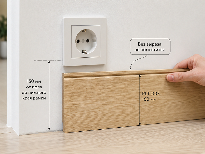
The finished floor is already in place, electrical work is complete, the socket group is installed, but the tall skirting board was only chosen at the final stage of finishing. The lower edge of the decorative frame is approximately 150 mm from the finished floor. The confirmed profile height for PLT‑003 is 160 mm. At first glance, the conflict is obvious: the skirting board is 10 mm higher than the lower frame edge.
160 − 150 = 10 mm.
But this does not automatically mean that PLT‑003 should be excluded from the project. First, it is necessary to determine what exactly is at the 150 mm mark: the lower edge of the decorative frame, the edge of the socket mechanism, the edge of the socket box, or the center of the electrical block. These are different geometric points. For ordering the skirting board, the visible and installation conflict with the frame and mechanism after final installation is what matters.
If 150 mm is indeed the lower edge of the installed decorative frame, and PLT‑003 must run along this wall without a break, the profiles overlap in height by at least 10 mm. In this case, the buyer needs to choose one of three solutions in advance: move the socket group higher, select a lower floor profile, or design a local bypass/termination of the skirting board around the socket. Purchasing the entire volume of PLT‑003 before this decision is risky.
In the general catalog you can to buy wooden baseboard of the required scale, but in our scenario the task is already more specific: the buyer has chosen PLT‑003 160 × 16 mm and wants to understand whether it can be kept without redoing the finished electrical work.
Below, we will not discuss the general topic of skirting board heights, but a specific joint: a 160-mm profile, a socket frame at the 150 mm mark, finished walls, and the need to make a commercial decision before paying for the order.

High wooden baseboard PLT-003 160 × 16 mm: which dimensions are confirmed by the card
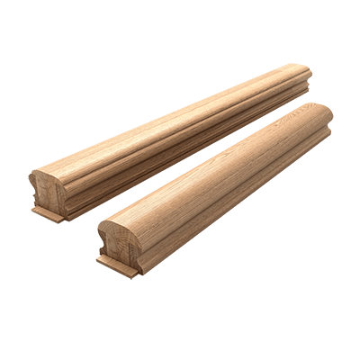
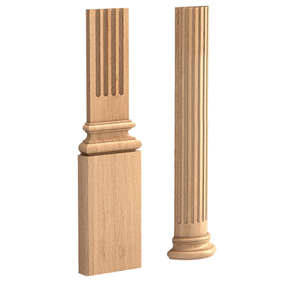
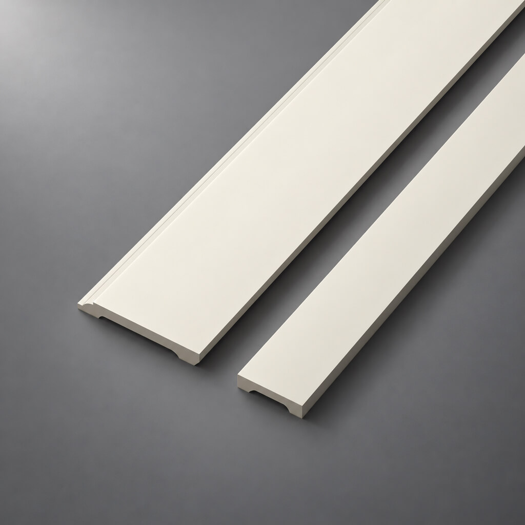
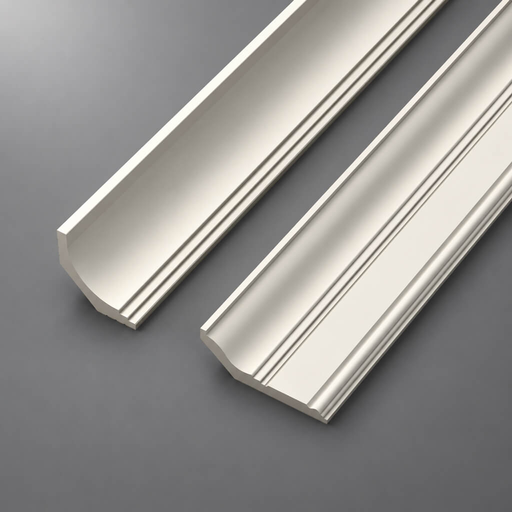
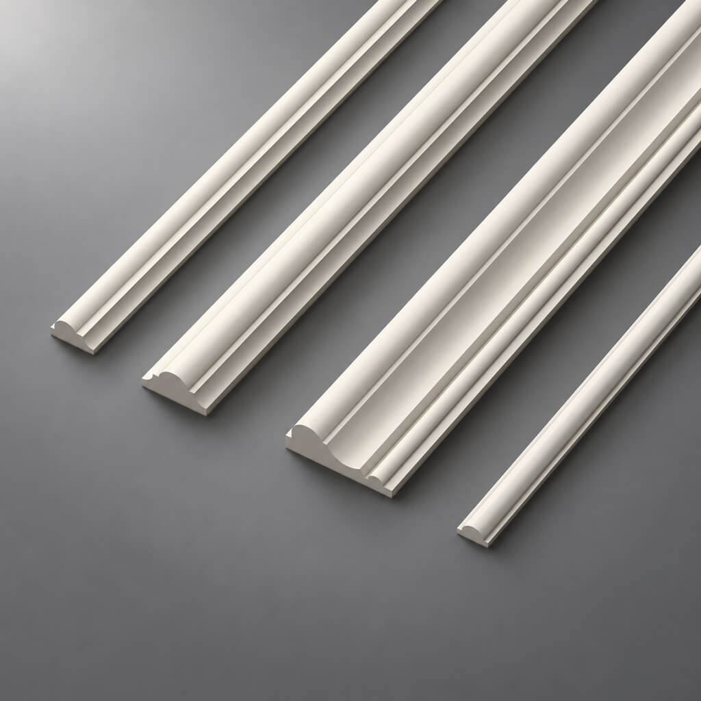
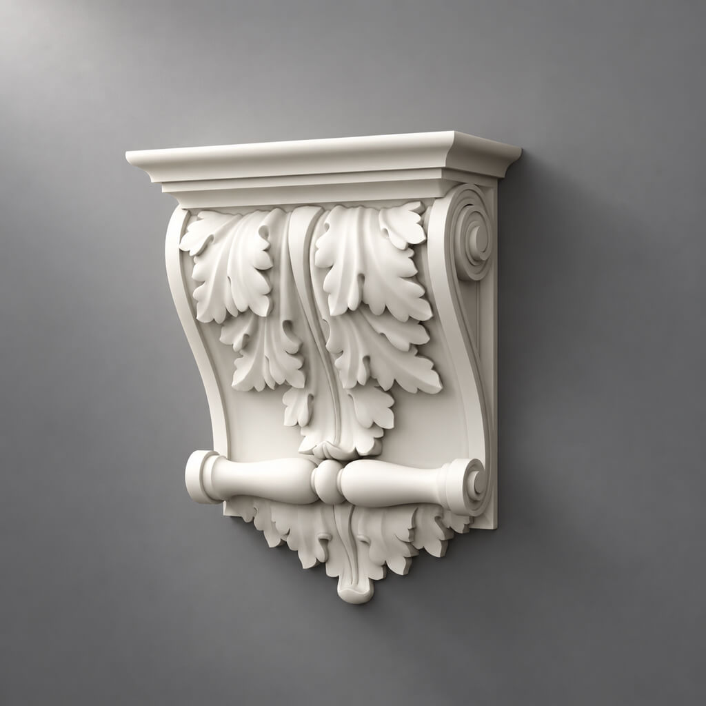
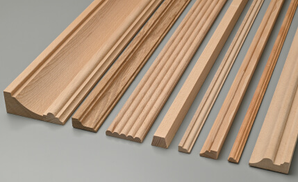
In the current product card, PLT‑003 is presented as a tall wooden skirting board / trim. For this article, the floor scenario is used. The main dimensions are the same in height and thickness: A = 160 mm, C = 16 mm. The standard length depends on the material.
| PLT‑003 configuration | Size | What matters near the socket |
|---|---|---|
| Moisture-resistant MDF | 160 × 16 × 2600 mm | Height of 160 mm determines conflict with the frame |
| Beech | 160 × 16 × 2400 mm | Same height; visible cutout is harder to fix with transparent finish |
| Oak | 160 × 16 × 2400 mm | Same height; texture makes local trims more noticeable |
Of the three numbers for conflict with electricals, the main one is 160 mm. Thickness of 16 mm affects the protrusion from the wall and the junction with the frame, but by itself does not resolve the vertical conflict. Length of 2400/2600 mm is needed for cutting only after all low sockets have been checked.
If the geometry is compatible, it is possible wooden plinth PLT-003 160×16 mm include in the final estimate. Until then, one sample or a full-size template is enough, not a full order around the entire perimeter.


Why a socket at a height of 150 mm really conflicts with a 160 mm plinth
If 150 mm is measured from the finished floor to the lower edge of the decorative frame, the upper boundary of PLT‑003 is at the 160 mm mark. This means the zones overlap by 10 mm.
But for an accurate solution, four concepts need to be separated:
Bottom edge of the decorative frame
This is the visible boundary that most often defines the aesthetic conflict. If the baseboard matches the frame, it may physically hit it or require a shaped cutout.
Bottom edge of the electrical mechanism
The mechanism is located inside the frame. Its dimensions may be smaller than the external decorative block. Sometimes the frame conflicts visually, while the mechanism allows for local wall finishing. But this still does not mean that the baseboard can be cut without a project.
Edge of the socket box
The socket box is hidden in the wall. Its position is important if electrical relocation is planned or if the baseboard mounting runs nearby. You cannot drill the wall around an electrical point without understanding the wiring layout.
Center of the socket
The center of the block often appears in electrical installation drawings, but it is of little use by itself for selecting PLT‑003. Two frames of different sizes with the same center will give different bottom edges.
Therefore, the notation "socket at a height of 150 mm" without specifying the measurement point is insufficient. For the baseboard, the physical contours of the finished block are what matter.
Our factory also produces:




Why 10 mm of vertical overlap does not yet equal 10 mm of physical collision
The calculation 160 − 150 = 10 mm shows that the decorative frame and the overall dimension of the plinth are in the same vertical zone. But this is not enough to assert that the solid material PLT‑003 will necessarily "cut into" the frame by a full 10 mm.
The reason is the cross-section shape. The card confirms the overall height A = 160 mm and the overall thickness C = 16 mm, but the tall plinth has a profiled shape. The upper part may have bevels, recesses, or offsets relative to the maximum thickness. Therefore, the actual physical intersection is determined not only by the rectangle 160 × 16 mm, but by the cross-section drawing of PLT‑003 and how far the socket frame itself protrudes from the wall.
This is a fundamental caveat. Two opposite simplified conclusions cannot be made:
- "160 is greater than 150, so the socket must definitely be moved";
- "the top of the plinth is shaped, so the frame will surely fit."
Both decisions without a drawing are guesses. The correct check is performed on a wall section.
Get Consultation
What should be on the section
Draw the vertical plane of the wall. From the finished floor, mark a line at 160 mm. Then apply the actual profile of PLT‑003 according to the drawing, preserving the maximum thickness of 16 mm and the shape of the upper part. After that, apply the lower part of the socket frame at the 150 mm mark and its actual protrusion from the wall.
In this form, three possible results are visible:
- Physical intersection. The frame enters the profile array. A transition, a different baseboard, or a special cut is needed.
- Vertical zones intersect, but the parts diverge in depth. Theoretically, the joint can exist, but the appearance, frame maintenance, and mounting gap need to be checked.
- The frame only visually matches the top line. There is no physical collision, but the gap may look too tight.
Why the frame's protrusion from the wall matters
The socket frame is not flush with the wall. It protrudes outward. If the top part of the baseboard recedes toward the wall, this protrusion sometimes creates space between the parts. But the exact distance depends on the specific series of electrical installation products, so it cannot be universally assigned in the article.
Take a side photo of the frame with a ruler, or measure its depth with a suitable tool. This figure is added to the cut along with the PLT‑003 profile.
Why the profile drawing matters more than the product photo
The frontal photo shows the decorative nature but provides almost no information about where exactly the profile has its maximum 16 mm thickness. For a solution near the socket, a cross-sectional drawing is needed. If it's not at hand, request it from the seller or use a real sample before ordering the full volume.
Therefore, the central conclusion of the article remains cautious: with a 150 mm frame, the conflict in overall height is confirmed, but the method of resolution is determined by the actual cross-section of PLT‑003 and the frame depth.
Calculation table: what the lower frame mark from 140 to 190 mm means
For a quick review of the entire apartment, it is convenient to compare the bottom mark of each frame with the top line of PLT‑003. The table below shows only vertical geometry. It does not replace checking the profile by depth.
| Bottom edge of the frame | Relative to PLT‑003 160 mm | Preliminary conclusion |
|---|---|---|
| 140 мм | Intersection 20 mm | Explicit height conflict |
| 145 мм | Intersection 15 mm | Explicit height conflict |
| 150 мм | Intersection 10 mm | Central scenario of the article |
| 155 мм | Intersection 5 mm | Borderline conflict |
| 160 мм | Touch along the overall line | a cut and assembly check is needed |
| 165 мм | 5 mm gap | very tight fit |
| 170 мм | 10 mm gap | check visually and by depth |
| 180 мм | 20 mm gap | usually geometrically calmer |
| 190 мм | 30 mm gap | significant visual gap |
This table is useful for initial sorting of points. For example, an apartment has ten outlets: two at 150 mm, one at 158 mm, the rest above 185 mm. Then there is no need to review the entire project — attention is focused on the three conflicting points.
Why the 160 mm mark is not automatically safe
Zero difference means the top trim line of the baseboard coincides with the bottom line of the frame. Any floor, installation, or size error can create contact. Additionally, the frame needs to be removed for maintenance. Therefore, a 'touch-to-touch' design requires a particularly precise layout.
Why 165–170 mm should also be checked with a template
Five or ten millimeters of visual gap can disappear due to a profiled top part, frame protrusion, or unevenness of the finished floor. On a long wall, even a slight floor level difference changes the relative mark of the baseboard and socket.
The finished floor is already laid: why you need to measure from it
In our scenario, the floor is ready, which simplifies the task: the base zero mark physically exists. You cannot use the old electrical drawing where the socket height might have been specified from the subfloor or design level.
Floor covering, underlayment, adhesive, leveling layer, and other structural elements change the actual surface mark. Even if the electrician correctly executed the project, after changing the floor build-up, the real bottom edge of the frame may end up at a different height relative to PLT‑003.
Therefore, the final measurement always sounds like this: 'from the top surface of the finished floor to the bottom outer edge of the installed frame.'
If adjacent rooms have different coverings
Parquet, tile, and other coverings may have different marks. You cannot measure sockets in the living room once and assume the same 150 mm applies in the hallway. Each room is checked from its own finished floor.
If the skirting board passes through a door transition
Different floor levels can cause a slight jump in the top line of the skirting board. This needs to be coordinated simultaneously with the architrave and sockets near the opening. A high profile makes such discrepancies more noticeable.
Multi-gang frame: which edge to consider for vertical and horizontal installation
For double, triple, or four-gang groups, you cannot rely on the center of a single mechanism. For PLT-003, the external lower contour of the entire decorative frame is important.
Horizontal frame
All mechanisms are at approximately the same height, so the bottom line of the block is usually common. Measure the external lower edge of the entire frame and its full width. The wider the block, the longer the potential cutout in the skirting board, making local trimming visually heavier.
Vertical frame
The lower mechanism can drop the common edge of the block noticeably below the center of the group. If the electrical drawing only contains the center mark, the actual bottom of the decorative frame must be measured separately after installation.
Why a wide block has a greater impact on the cutout decision
A single frame creates a relatively short local conflict. A triple horizontal group requires a large notch in a high profile. Even if such a notch can be fabricated, it may disrupt the decorative rhythm of PLT-003 over a significant length. In this case, relocating the electrical wiring or choosing a different profile becomes more attractive.
What to measure before buying a wooden skirting board PLT‑003
Before ordering, it is enough to walk along the wall with a tape measure and record ten parameters.
1. From the finished floor to the lower edge of the frame
This is the main figure. It should be measured from the already finished floor covering, not from the rough screed.
2. Overall frame size
Record the height and width of the decorative block. For a double or triple frame, the dimensions may differ from a single one.
3. Position of the mechanism inside the frame
If a special local unit is being considered, it is important to know how much free space exists between the mechanism and the lower boundary of the frame.
4. Position of the socket box
This information is needed by the electrician if the block is being moved.
5. Number of mechanisms in the group
Single, double, triple, and long horizontal frames require different compositions.
6. Block orientation
A vertical multi-gang frame is especially sensitive to a high baseboard: the lower module can be much closer to the floor.
7. Offset from the wall corner
If the socket is both low and close to the corner, the local cutout may also conflict with the corner joint of the baseboard.
8. Distance to the door trim
Near the door, three elements arise: the baseboard, the trim, and the socket frame. They cannot be designed separately.
9. Thickness of the wall finish
If the socket is installed in a decorative panel or a thick layer of finish, the frame may protrude more compared to the 16-mm PLT-003.
10. Furniture in front of the socket
If the unit is hidden by a cabinet, the aesthetic priority may change, but access to the socket must still be maintained.
The lower edge of the frame is 150 mm, and the wooden skirting board is 160 mm: three possible solutions
Move the socket group higher
This is the cleanest architectural solution if the renovation still allows electrical work. The PLT-003 line remains continuous, the decorative frame does not require a cutout, and the entire high profile works as intended.
But moving the socket is not a decorative operation. It must be performed by a qualified electrician, taking into account the existing wiring, mounting boxes, and the requirements of the specific electrical installation system. The article does not specify the height of the new socket and does not replace the electrical design.
Choose a lower wooden floor skirting board
If the electrical work is already fully completed, the walls are painted, and moving one or more groups is destructive, a lower profile may be more rational. Then the height is chosen based on the minimum free space under all frames, not on one problem point.
For comparison, you can buy a wooden baseboard of a different height in the same product category. This is preferable to chaotically cutting PLT-003 around five or six sockets across the room.
Modify the local PLT-003 unit
Sometimes the baseboard can be finished before the outlet, with a special return to the wall or a local cutout designed. But such solutions must be drawn at a 1:1 scale before cutting. A tall decorative profile does not forgive random rectangular notches.
A local bypass is reasonable if there are few conflict points and they are in less visible places. If low outlets run along the entire perimeter, the special joint ceases to be local and becomes a systemic problem.
Is it worth cutting PLT-003 around an already installed outlet
Technically, a local cutout is possible in some projects, but it cannot be recommended as a standard solution. At least five factors need to be assessed.
The shape of the profile itself
PLT-003 is a tall decorative baseboard. If the frame crosses the profiled upper part, the cutout disrupts the relief and becomes more noticeable than on a simple flat plank.
Depth 16 mm
The outlet frame protrudes from the wall by its own amount. You need to look at the side view: the baseboard may not only approach the frame in height but also hit it in depth.
Repeatability of the joint
One neat cutout can be made using a template. Five different frames at different heights turn installation into a series of individual cuts, where an error in one piece ruins a long strip.
Finishing
For MDF, the open end needs to be re-prepared for enamel. For beech and oak, the shaped cutout exposes transverse fibers and requires careful finishing.
Electrical safety
The baseboard should not overlap the frame, hinder removal of the front part, or block access to the mechanism's mounting screws. The electrical point must remain serviceable.
Therefore, the cutout is the third option after evaluating moving the socket and choosing a different profile, not the first solution of "the installer will trim it on site."
Local assembly around the socket: when it is worth designing at all
How to draw a local cutout before cutting
Remove the frame only if an electrician does it or the work is safely performed with the line disconnected, then accurately measure the outer contour. On paper at a 1:1 scale, draw PLT-003 with a height of 160 mm and overlay the frame at the actual height.
After this, it will become visible:
- which part of the profile intersects with the frame;
- whether the top line remains continuous;
- is the open end visible;
- is it possible to keep the same relief on the left and right;
- does the cutout not look like a random "hole".
If the layout looks bad on paper, a real wooden profile won't improve the situation. Then it's better to move the socket or change the baseboard.
When moving a socket is more rational than abandoning PLT-003 throughout the room
If there is only one problem point and the entire interior is designed around a high 160-millimeter baseboard, a local electrical rework may be more logical than changing the profile on all walls.
You need to compare not only the cost of work, but also the consequences:
| Solution | What changes |
|---|---|
| Move one socket | Local electrical work, wall restoration, keeping PLT-003 around the entire perimeter |
| Choose a different baseboard | The architectural scale of the entire room changes |
| Make a cutout | The electrical wiring remains, but a special noticeable node appears |
Actual prices for moving outlets without an up-to-date local source are not provided in the article. The buyer compares a specific electrician's estimate with the cost and visual effect of another baseboard.
If there are five low outlets: is it worth buying a tall baseboard
Five conflict points change the decision. What is reasonable for one outlet becomes inconvenient in a series.
| Situation | What to check |
|---|---|
| One problematic outlet | Local relocation or a special node |
| Several outlets along one wall | Systematically reconsider the electrical wiring or the profile height |
| Sockets around the entire perimeter | Compare another baseboard |
| Part of the points are hidden by furniture | Check actual visibility and access |
| Electrical work is not yet completed | First bind heights to PLT-003 |
If five frames start at 150–155 mm, making five shaped cutouts in the tall profile almost certainly means the architectural specification and electrical work are not coordinated. Better to fix the system rather than mask each conflict individually.
The wooden floor baseboard is better coordinated before the final installation of sockets
Tall baseboards 120–160 mm noticeably extend into the lower wall zone. If their exact article is selected in advance, the electrician can coordinate the height of decorative frames with the architectural project before the final installation of mechanisms.
This does not imply a universal rule of “raise all sockets above 160 mm.” The height depends on the project, room purpose, furniture, and applicable requirements. But PLT-003 itself must be present on the finishing drawing before the points are finally fixed.
What to do if the concept changed after electrical installation
A common scenario: the electrician was guided by a regular baseboard of 70–100 mm, and later the designer chose a tall PLT‑003. Then the conflict is not a product defect and not necessarily the electrician's mistake. The architectural specification simply changed after the completion of the adjacent work.
The correct response is to re-coordinate three systems: electrical, baseboard, and furniture. Trying to "fit" one of them on site without a drawing creates random solutions.
Socket near the door: check the door casing at the same time
If a low socket is located near a doorway, three geometries meet in one zone:
baseboard → door casing → socket frame.
Suppose the frame vertically intersects with PLT‑003, and horizontally is only a few centimeters from the door casing. Moving it up may resolve the conflict with the baseboard but create a new conflict with the door trim. Therefore, the point cannot be moved only vertically without a general view of the wall.
On a full-size mockup, mark the outer contour of the door casing, the top line of 160 mm, and the socket frame. This allows a decision to be made before electrical rework.
PLT‑003 made of moisture-resistant MDF: what changes near the socket
Moisture-resistant MDF in the PLT‑003 card has dimensions of 160 × 16 × 2600 mm. For a conflict with a low socket, the material does not change the main geometry: the frame still starts at 150 mm, and the profile rises to 160 mm. But MDF affects how a local cutout or end termination will look.
If the baseboard is painted with an opaque enamel, the local cutout can be prepared together with the other parts. The open MDF edge requires careful treatment and priming according to the technology of the selected system. If the cutout is made after the finished painting, the intervention site is harder to bring to a factory-neat appearance.
For a painted project, you can buy MDF skirting board and compare other profiles in the category. If a lower MDF profile resolves the conflict with all sockets at once, this may be more rational than five individual cutouts in PLT‑003.
Why moisture resistance does not resolve the conflict with the frame
Moisture-resistant MDF refers to the base material, not the height. The profile is still 160 mm. You cannot assume that MDF is "easier to cut, so the problem disappears." The geometry and appearance of the joint remain the main limitation.
When MDF is more convenient for a local solution
If the entire interior is painted in one color and the socket frame is also neutral, a tinted end cutout can be made less noticeable. But this must be decided before installation so that all cut edges undergo the same preparation.
Material of PLT‑003 and quality of local cutout
Wooden baseboard PLT‑003 made of beech or oak near sockets
Beech and oak have the same profile of 160 × 16 mm, but a standard length of 2400 mm. With a transparent or semi-transparent finish, the local cutout around the socket is more noticeable than with painted MDF, because the end fibers are exposed.
Beech
Beech has a calmer structure, but the cross-cut still differs from the face surface. If the socket frame requires a shaped bypass, the edge must be sanded and finished as carefully as the main profile.
Oak
Oak has a pronounced texture. An uneven or overly complex cut near a plastic frame can visually "break" the pattern. Therefore, for oak PLT‑003, relocating the socket often looks aesthetically cleaner if it is technically possible and economically justified.
The request for a natural wood baseboard is appropriate in this block: the natural material enhances the value of a clean continuous line and makes random local cuts more noticeable.
MDF moldings and tall baseboards: when to look beyond PLT‑003
If the main problem is systematically low sockets throughout the room, it is useful to compare not one card but several MDF profiles of lower height. To do this, you can open the section MDF Molding.
The point of such a comparison is not to replace PLT‑003 with "something similar," but to find a height that does not intersect with electrical frames while maintaining the desired architectural scale. If the new profile is 20–30 mm lower, the conflict may disappear without electrical work.
Full-size PLT‑003 template before ordering
The most useful tool for this topic is a paper or cardboard strip exactly 160 mm high. It does not need to be complex: the outer contour of the top line is what matters.
Secure the template with painter's tape along the entire wall and walk around the room along the perimeter. Conflicts that are not visible on the plan immediately become apparent.
What to mark on the template
- all sockets and switches in the lower zone;
- door casings;
- furniture side panels;
- radiators and pipes;
- niches;
- panels and decorative inserts;
- floor door stops;
- points where the profile should end.
If the template overlaps the socket frame by 10 mm, it is immediately visible. If the frame is at 170–180 mm, a real air gap appears that can be visually assessed.
Why a template is better than a tape measure
A tape measure answers the question “how many millimeters.” A template shows the entire visual band of 160 mm. It helps understand whether the profile is too tall for a specific wall at all, and simultaneously reveals all conflict points.
Full-scale check of the entire room and boundary heights
How to check all outlets in a room in one pass
Make a simple table. For each point, record the bottom edge of the frame, the number of posts, the distance to the corner, and whether there is a door nearby.
| Rosette | Bottom edge of the frame | Conflict with 160 mm | Next action |
|---|---|---|---|
| R1 | 150 мм | Yes, 10 mm overlap | Move / different profile / local node |
| R2 | 165 мм | Formally no, but the gap is only 5 mm | Check the frame and profile at full scale |
| R3 | 180 мм | No | Assess the visual 20 mm gap |
| R4 | 145 мм | Yes, 15 mm overlap | Priority rework |
Such a table shows whether the problem is systemic. If only one point conflicts, a local solution still makes sense. If four out of five — PLT‑003 and the existing electrical system are poorly compatible as a whole.
Edge case: the frame starts at exactly 160 mm
If the bottom edge of the frame is exactly at 160 mm, the baseboard and frame touch along a single line. Formally, there is no vertical overlap, but such a joint cannot be automatically considered successful.
Need to check:
- floor flatness;
- actual profile height;
- frame installation tolerance;
- possible expansion of the finishing layer;
- frame protrusion in depth;
- need to remove the frame for maintenance.
Visually, a 0 mm gap can also look too rigid. Often a small air gap is perceived as neater, but its size is determined by the design scheme, not a universal norm.
Edge case: bottom edge of the frame at 165 mm
At 165 mm, only 5 mm remains above the baseboard. Geometrically, the profile no longer intersects with the frame, but the installation and visual margin is minimal.
If the floor has a slope or the baseboard rises by a few millimeters at one point relative to the adjacent wall, the 5 mm may disappear. Therefore, this case must be checked with a full-size template.
Edge case: frame at 180 mm
Here, the pure vertical gap is 20 mm:
180 − 160 = 20 mm.
This is already a noticeable gap, but the side profile needs to be checked finally: both the frame and the baseboard protrude from the wall. If the decorative relief PLT‑003 extends forward, the visual distance may be perceived differently.
Breaks, corners, and furniture: special places around a low socket
Can the baseboard be finished before the socket and continued after it
Technically, a break can be made, but it must look intentional. Two high-profile ends will appear on the wall. For a single outlet, this is often worse than a neat relocation of the electrical point or a different baseboard.
A break makes more sense if the outlet is built into a separate decorative panel, furniture block, or architectural insert that itself creates a boundary. If the frame simply sits in the middle of the wall, two PLT‑003 ends look like an obstacle bypass rather than a designed joint.
When a local return of the baseboard to the wall is better than a rectangular cutout
If the profile allows for a neat finish of the line with a short return to the wall before the outlet, such a joint can look cleaner than a cutout in the upper part. After the frame, the line starts anew only if it is compositionally justified.
But a universal miter cut for PLT‑003 cannot be assigned without a profile drawing. First, you need to see the actual cross-section, make a mockup, and decide how the end will be finished.
Low outlet near an external corner
If the frame is both low and close to an external corner, the baseboard must also form a corner joint. A cutout around the outlet can ruin both lines at once.
Here, it is especially useful to move the point higher or slightly change its position if the electrician confirms the possibility. If relocation is not possible, a lower profile often gives the cleanest result.
Low outlet near an internal corner
At an internal corner, the frame can interfere with joining two long runs. As a result, the installer simultaneously fits the corner and the cutout. This increases the risk of error.
If the distance from the frame to the corner is small, first draw both whips to scale and check the installation sequence. Sometimes it is more reasonable to finish one side earlier or change the profile throughout the room.
Socket hidden by furniture: can the conflict be ignored
If a cabinet stands in front of the socket, the decorative conflict may be invisible, but the electrical point must remain accessible. You cannot cover the frame with a baseboard just because it is not visible.
Moreover, furniture can be moved. If PLT-003 has a cutout of an odd shape, the node will be exposed after rearrangement. Therefore, concealment reduces aesthetic importance but does not cancel technical importance.
If the socket is needed for stationary furniture
For example, the point serves a TV cabinet, console, or built-in wardrobe. In this case, a separate furniture node can be considered: the baseboard ends at the furniture, and the socket remains within its zone.
But this is already a solution for the entire wall composition, not a PLT-003 cutout directly around the electrical frame.
How to compare moving one socket and changing the profile without prices
Without a local electrician's estimate, it is impossible to honestly say which option is cheaper. But you can compare the number of affected elements.
| Factor | Moving one socket | Change PLT-003 to another profile |
|---|---|---|
| Affected area | Local | Entire room perimeter |
| Electrical fixtures | Being redone | Remains |
| Walls | Local restoration will be required | Without electrical installation intervention |
| Design | High baseboard is preserved | The scale of the bottom line changes |
| Layout | The original PLT-003 remains | A new profile is recalculated |
If there is one problem point, relocation often has fewer architectural consequences. If there are many problem points, changing the profile becomes a more systemic solution.
Installation, safety, and cutting after electrical approval
Materials for installation and finishing: what will be needed after selecting the node
After the decision on outlets is made, you can move on to adhesive, primer, and final treatment. Before that, buying installation materials is premature: MDF for enamel and solid wood for transparent finish require different systems.
In the section Mounting and finishing materials you can view the corresponding category. The specific composition is selected based on the wall substrate, PLT-003 material, and the manufacturer's instructions.
How to avoid damaging electrical wiring during baseboard installation
In the outlet area, you cannot drill or fasten the profile without understanding where the cables run. The route may run vertically or horizontally from the socket box. Therefore, mechanical fastening near an electrical point is coordinated with an electrician or checked in a safe manner.
The article does not specify drilling depth or fastener type: these parameters depend on the wall, profile, and installation scheme.
How to calculate the number of PLT-003 after resolving the issue with sockets
First, all conflict points and the final wall layout are fixed. Only then are the strips counted.
For MDF, the standard length is 2600 mm, for beech and oak — 2400 mm. The net perimeter is divided into separate segments, taking into account doors, furniture gaps, and special endings.
Example
After all deductions, the open baseboard line is 13,400 mm. Simple division gives:
13,400 ÷ 2600 ≈ 5.15 — at least 6 MDF strips by net amount.
13,400 ÷ 2400 ≈ 5.58 — at least 6 beech/oak strips by net amount.
But the actual cutting map may require more due to long walls, corners, and places where the baseboard must end at a socket zone or furniture.
Why socket cutouts increase the risk of waste
If a long strip of 2400 or 2600 mm gets a complex cutout almost in the middle, a marking error can ruin the entire piece. Therefore, areas with sockets should be highlighted on the cutting map in advance.
Sometimes it is wiser to use a separate short segment for a complex node, keeping a long solid plank for an open wall. This is especially relevant for oak under a transparent finish.
Mistakes before buying a tall wooden baseboard
Mistake 1. Choosing PLT-003 only by photo
The photo does not show the real 160 mm line relative to the outlets of a specific room.
Mistake 2. Measuring to the center of the mechanism
For the conflict, the outer edge of the finished frame is important.
Mistake 3. Checking only one outlet
Other blocks may be lower and create a systemic problem.
Mistake 4. Ordering the entire volume before the mockup
After delivery, it turns out that the tall profile conflicts on several walls.
Mistake 5. Relying on an on-site cut
A complex profile and finishing can make such a bypass noticeable and expensive.
Mistake 6. Not checking switches and low-current points
Not only power outlets can conflict.
Mistake 7. Not checking the door casing
The outlet may end up squeezed between a tall baseboard and the door frame.
Mistake 8. Moving the point upward without an overall wall layout
You can resolve the conflict with the baseboard but create a conflict with furniture or the casing.
Mistake 9. Trimming solid wood after transparent finishing
The new end will be difficult to restore to its original appearance.
Mistake 10. Considering 160 mm as the only significant dimension
The thickness of 16 mm and the profile shape also affect the contact with the frame in depth.
Practical scenarios: from a single outlet to a system conflict
Practical scenario: one outlet at 150 mm in a long living room
Suppose there is only one frame in the room that conflicts with PLT‑003. The other electrical points start above 190 mm, door
Practical scenario: one outlet hidden by a cabinet
If the cabinet is permanently placed in front of the outlet, the visible conflict may almost disappear. But the baseboard still should not overlap the frame or hinder access to the mechanism. If the furniture has its own side panel or plinth, the baseboard can be finished at the furniture, and the electrical point can be left in a separate hidden zone.
This option is especially useful when moving the outlet is not functionally necessary, and the interior line is still covered by furniture. But the solution must be tied to the stationary layout. If the cabinet can be removed, the gap in the baseboard will be exposed.
Practical scenario: an outlet at 150 mm near a door opening
Suppose the frame is 60 mm from the outer line of the trim. Moving it up resolves the vertical conflict, but may make the outlet visually too close to the door trim. The cutout in PLT‑003 will also be noticeable because the area is in the passage.
In such a situation, one full-size drawing is needed: the trim, PLT‑003, and the outlet frame. Sometimes a slight horizontal shift of the electrical point along with raising it gives a cleaner result, but the specific possibility is determined by the electrician.
Practical scenario: sockets are only in junction boxes yet
If mechanisms and decorative frames are not installed yet, the project is at a more advantageous stage. You can apply the PLT-003 160 mm template, determine the future top line, and agree on the final frame height before final assembly.
This does not cancel electrical installation requirements, but it reduces the risk that the finished frame ends up 10 mm below the required line. That is why a high baseboard is better included in the working documentation earlier.
Practical scenario: a switch or low-current frame is equally low
Not only power sockets need to be checked. Internet, television, audio outputs, thermostats, sensors, and special low switches may be in the same 160-millimeter zone.
One template across the entire room allows detecting them before ordering. Otherwise, the buyer will solve the problem with one socket, and after profile delivery will discover a second conflict on the adjacent wall.
When it is better not to buy PLT-003 for this room at all
There are scenarios where the right decision is to refuse a specific high profile, even if it looks appealing visually.
- most sockets start below or around 160 mm;
- several door units simultaneously conflict with the high profile;
- relocating the electrical wiring is already impossible without major renovation;
- individual cutouts would have to be made along the entire perimeter;
- furniture and radiators also occupy the lower band of the wall;
- the architectural value of the 160-millimeter line does not justify the scope of alterations.
Such a conclusion does not mean that PLT-003 is "unsuccessful." It means that the specific apartment already has a different geometry of engineering and furniture elements.
Buy PLT-003 or change the profile: the final decision logic
When PLT-003 is worth keeping despite one problematic outlet
If the high profile is part of the overall architecture—for example, coordinated with large door trims, classic wall panels, and room height—one low outlet may be a weak reason to change the entire solution.
In such a case, it is worth first checking the possibility of correctly relocating the point or a local furniture unit. Changing the baseboard changes the entire room, while relocating one outlet changes only one section.
How to make a decision tree before purchasing
| Question | If yes | If no |
|---|---|---|
| Is the bottom edge of the frame below 160 mm? | There is a vertical conflict | Check the actual gap |
| Is there only one problem point? | Consider a local relocation | Check for a systemic change in profile/electrical |
| Can the electrical still be redone? | Get an electrician's solution | Compare another baseboard or local joint |
| Does the cutout look neat on the template? | Check the technology and maintenance of the frame | Do not perform random trimming |
| Is PLT-003 important for the whole concept? | Keep the profile with reasonable local rework | It is easier to choose a smaller height |
Such a tree excludes impulsive purchase. The decision is formed from the real number of conflict points, not from a single difference of 160 - 150.
How to check the cutout for socket maintainability
Even a beautifully drawn bypass can turn out to be impractical if the frame cannot be removed. Before approving the layout, you need to understand how a specific series of electrical installation products is maintained.
The plinth must not:
- overlap the frame from the top or bottom so that it is clamped;
- block access to fastening elements;
- interfere with removal of the decorative part;
- put pressure on the mechanism;
- create contact with wiring.
If replacing the socket requires first dismantling a long baseboard, the unit is poorly designed.
How to check the side view of PLT-003 and the frame
Height is only one coordinate. The thickness of PLT-003 is 16 mm. The decorative frame also protrudes from the wall. If their vertical zones are close, the side profile shows whether physical contact occurs.
Make a simple wall cross-section: the wall plane, PLT-003 with a depth of 16 mm, and the actual protrusion of the frame. If the frame starts at 165–170 mm but protrudes significantly and has a rounded lower edge, the visual distance may be less than it appears in the front view drawing.
Why the frame size should be measured after final installation
The catalog size of the mechanism does not always match the actual frame chosen by the designer. The same mechanism can be used with different decorative series and multi-gang frames.
Therefore, the final check is performed against the actually installed or precisely selected frame, not against the overall size of the recessed box.
How to mark conflict points on the plan
On the room plan, assign a number to each problematic outlet: R1, R2, R3. Next to it, write down the lower mark of the frame and the decision made.
| Point | Mark | Solution | Status |
|---|---|---|---|
| R1 | 150 мм | Move higher per the electrician's project | Approve |
| R2 | 178 мм | PLT‑003 passes | Check with template |
| R3 | 152 мм | Hidden by furniture, the baseboard ends at the side panel | Coordinate the furniture unit |
Only after each point has a status does the final calculation of the rods begin.
Wall elevation: how to communicate the PLT‑003 conflict to the designer and electrician without saying "the outlet is too low"
For coordination, a simple wall elevation with dimensions works best. On it, the horizontal line of the finished floor is taken as zero, the top of PLT‑003 is drawn at the 160 mm mark, and each outlet frame is drawn according to its actual outer contour.
For each point, it is enough to label four coordinates: the distance from the corner to the left edge of the frame, the bottom mark, the full width, and the full height of the frame. If there is a door nearby, add the outer line of the trim. If furniture is planned, add its side contour.
Such a layout immediately shows that the problem of one frame at 150 mm differs from the problem of a triple block next to a door. The electrician sees which point needs to be assessed for relocation; the carpenter or baseboard installer understands where a special joint will be required; the designer evaluates the overall visual result.
Why a single mark of the socket center is not enough
For example, the center of the block is recorded on the plan, but a different series of decorative frames is chosen. The center of the electromechanism may remain the same, but the outer contour will change. This is crucial for PLT-003 because the conflict is created specifically by the bottom edge of the finished frame.
What to mark after the decision is made
After approval, one status is placed near each point: "PLT-003 passes," "the socket is moved by the electrician," "the baseboard ends at the furniture," "local joint per drawing." Then the installation crew does not make decisions anew on site.
The layout is especially useful when there are multiple rooms. You can quickly see that in the living room the high profile is preserved without modifications, while in the bedroom five low points make a different baseboard more rational. This allows not changing the architectural concept of the entire apartment because of one room.
When the layout needs to be updated
Any change to the finished floor, the series of socket frames, the door trim, or furniture near a point requires re-verification. The old drawing cannot be considered current if the outer contour of at least one participant in the joint has changed.
What to send to the manager before ordering PLT-003
It is useful for the manager to send not only the article number, but also a brief project specification:
- PLT‑003;
- material — moisture-resistant MDF, beech or oak;
- number of rooms;
- photos of all low sockets;
- size from finished floor to bottom frame;
- wall layout with lengths;
- photos of doorways;
- finishing solution;
- preliminary number of strips;
- list of places where local termination or cutout is planned.
After approval, you can order a tall wooden baseboard PLT-003 already for a proven interior.
Order, acceptance, and delivery after approval of the joint
What to check upon receiving PLT-003
Before cutting and finishing, verify the article, material, size, and quantity. For MDF, expect 160 × 16 × 2600 mm; for beech/oak — 160 × 16 × 2400 mm according to the main size table in the card.
If cutouts near sockets are planned, set aside the straightest and visually suitable strips for open long walls, and plan sections with complex trimming separately. For solid wood, consider the wood grain.
Delivery conditions for long-length PLT-003
Profiles of 2400 and 2600 mm must be delivered and carried in without damage. The PLT-003 card separately mentions a rigid packaging frame. Before payment, it is worth checking payment and delivery terms, the carrying route, and the storage location before installation.
If renovation is still ongoing, do not unpack the entire volume near dusty or wet work without necessity.
Where to buy wooden skirting board PLT-003 after electrical inspection
If the frames are raised or confirmed not to intersect with the 160 mm top line, PLT-003 can be ordered in the selected material. If the conflict remains on several walls, lower skirting boards are compared first, and only then the perimeter is recalculated.
The main commercial principle here is simple: do not buy a high profile until all electrical frames are placed on the 160 mm template. This is cheaper than fitting ready-made material to already discovered conflicts.
FAQ about PLT-003 and low sockets
What is the height of PLT-003?
160 mm.
What is the thickness of PLT-003?
16 mm.
What is the length of the moisture-resistant MDF version?
2600 mm according to the main table on the card.
What is the length of PLT-003 made of beech and oak?
2400 mm according to the main table of product variants.
Will PLT-003 overlap the frame if its bottom edge is at 150 mm?
In terms of vertical geometry, the zones overlap by 10 mm. Either the electrical/profile needs to be changed, or a local junction needs to be developed.
What exactly should be measured on the outlet?
The distance from the finished floor to the external bottom edge of the installed decorative frame, as well as its full dimensions and the position of the mechanism.
Can PLT-003 be cut out around the socket?
Sometimes it is technically possible, but it is not a universal solution. The profile shape, finish, frame maintenance, and the appearance of the layout need to be checked.
Is it better to move the socket or choose a lower baseboard?
If there is only one conflict point and PLT-003 is important for the entire interior, it is rational to first evaluate the relocation. If there are many low points, another profile may be systematically simpler.
Do all sockets need to be moved?
Only those that actually conflict with the selected junction. Each point is checked separately.
Can the frame be placed exactly at the 160 mm mark?
Formally, there is no vertical overlap, but zero clearance requires checking floor flatness, actual dimensions, and frame serviceability.
If the frame starts at 165 mm, does the conflict disappear?
Only 5 mm remains. This is a borderline case that is better checked with a 1:1 template.
Can I buy PLT-003 made of moisture-resistant MDF?
Yes, the current card shows moisture-resistant MDF 160 × 16 × 2600 mm.
What to do if the socket is near the door?
Check PLT-003, the casing, and the frame simultaneously on one full-size drawing.
What to do if the socket is hidden by furniture?
Do not block access to the electrical point. The baseboard can end at the furniture if it is consistent with the overall composition.
How to check compatibility before purchasing?
Make a template 160 mm high, run it along the entire perimeter, and mark all frames, doors, furniture, and utility elements.
When is it better to refuse PLT-003?
When low sockets and other elements systematically cross the 160-mm zone throughout the room, and redoing the electrical work is not justified.
Result: with a lower frame edge of 150 mm, PLT-003 cannot be ordered without resolving the junction point.
PLT-003 has a confirmed height of 160 mm. If the lower edge of the finished socket frame is indeed located at a height of 150 mm from the finished floor, the baseboard extends into its vertical zone by 10 mm. This is a real conflict, not a matter of taste.
But the right action starts with verification: make sure that 150 mm refers specifically to the frame; measure all electrical points; create a full-size 160-mm template; check trim, furniture, and other obstacles. After that, it becomes clear whether the issue is local or systemic.
With one problematic socket, you can compare moving the electrical work with a local junction solution. With five low points, it is more reasonable to reassess the baseboard height for the entire room. A cutout around the frame is acceptable only as a designed detail, not as an installer's improvisation.
If PLT-003 remains in the project, only after resolving all conflicts do you choose MDF 2600 mm or beech/oak 2400 mm, create a cutting map, and place the order. This way, the tall baseboard becomes part of the agreed architecture, not a reason to redo already finished electrical work.