Article Contents:
- A product card does not replace a project layout
- The outer frame size and the free field inside it are different values
- First calculate the inner area, and only then place NPU.VRS-018
- What to record for NPU.VRS-018 in the specification
- Why the item code matters more than the words “decorative overlay”
- Mark out a symmetrical composition starting from the panel axis
- Why equal panel height does not make them the same type
- Instead of eighteen separate frames, create several panel types
- Everything for construction and renovation: first the reference module, then the series
- A full-size paper template should be made before purchasing the series
- What can and cannot be assessed using the template
- Molding and NPU.VRS-018 should be counted as a single composition
- Mini-specification for each panel type
- The quantity of NPU.VRS-018 is counted by module types
- If an element is used as a pair, it should be a separate module type
- Renovation products in bulk are counted by modules, not by wall area
- The quantity of overlays and the quantity of molding are calculated using different methods
- The series requires one control dimension that cannot be interpreted differently
- The installation template turns the approved scheme into a repeatable result
- The end panel near the door is often not a standard one
- You cannot force a single module to work in any geometry
- Before approving the template, switches, sockets, wall lights and other engineering elements are checked
- The last frame in the row often changes the final quantity of NPU.VRS-018
- For a large series, one real panel is produced first
- NPU.VRS-018 and the moulding must have a coordinated finishing system
- Order acceptance: SKU and quantity are checked, not just the boxes
- Zone marking links warehouse assembly with the project
- How to account for the reserve and not turn it into a random number
- What to do if the number of panels changes after ordering
- How to check a series for hidden differences before the final order

A single decorative frame in a visualization may look flawless, but when moving to a series of identical wall panels, the task changes. It is no longer enough to simply choose a moulding element; you must prove that it physically fits into every variation of the frame, is correctly positioned relative to the axes, does not conflict with switches, wall lights, doorways, or furniture, and then convert the approved composition into the exact number of products for the order.
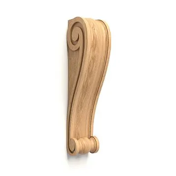
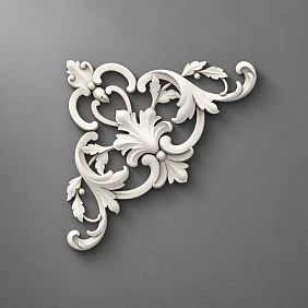
As a specific element, let us consider Molded decor NPU.VRS-018. In the current STAVROS product page, the material is listed as polyurethane, and the size is written as A × B × C × L: 196 × 196 × 14 × 265 mm. This data must be transferred to the working schedule without simplifying it to the wording “decor approximately 200 mm.” For the project layout, what matters is not the approximate scale, but the actual outer contour of the product and the free field inside the specific frame.
The main mistake in serial wall decoration is to immediately multiply the number of frames by one decorative element. If a project has 18 panels, that does not yet mean that 18 NPU.VRS-018 are needed. Some panels may be wider, some narrower; in one type, the decor may be used once, in another — as a pair, and the end panel near the door may even require a separate solution without this element.
The correct sequence is different: wall type → panel type → free decorative field → full-size check of NPU.VRS-018 → approved module → number of modules → number of products for the order.
This approach is useful for the designer, the specifier, and the installer. The designer gets a controlled composition, the purchaser gets an accurate specification, and the installer gets repeatable marking instead of having to determine the position of the decor “by eye” every time.
A product page does not replace a project layout
A product page answers the question of what this product is: its SKU, material, dimensions, available options, and other product characteristics. But it does not know the geometry of your wall. Even if the product page specifies the exact size of NPU.VRS-018, it does not automatically follow that the element is suitable for a 500 mm wide frame or for any 800 mm high panel.
The reason is simple: the decorative element is not installed into the outer rectangle of the panel, but into the inner free field that remains after accounting for moldings, gaps, abutments, and other parts of the composition. For a frame with an outer size of 500 × 800 mm, the actual field for the decor is always smaller. How much smaller depends on the profile and the method used to construct the frame itself.
Therefore, for the project, an entry such as: “Panel 500 × 800 mm, decor 196 mm — fits” is not enough. A different entry is needed: “Inner free field after constructing the frame — W × H; the actual contour of NPU.VRS-018 has been checked at a 1:1 scale; the design clearances have been confirmed.”
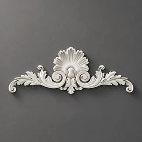
This is especially important when the product has a complex ornamental contour. The nominal size cannot be interpreted as an abstract square if the real shape protrudes in certain directions. For a full-size check, one should refer to the current product card, drawing, or physical sample, rather than drawing a conventional rectangle just because the two numbers in the dimension line are the same.
The product card provides the initial data. The design layout turns them into a solution for a specific wall.




The outer size of the frame and the free field inside it are different values
Let us imagine a wall panel with an outer size of the decorative frame of 500 × 700 mm. On the plan, these numbers look sufficient for a relatively compact overlay. But after installing the molding, the inner area will decrease.
For a simple rectangular frame, the preliminary inner width can be estimated with the formula: inner width = outer width of the frame − left part of the profile − right part of the profile. The inner height is calculated similarly.
If the profile visually or structurally extends into the frame by the same amount, the calculation can be simplified to twice the width of that section. But in a real project, it is better to work with the actual geometry of the selected molding and the joint assembly, because the decorative width of the profile and the useful reduction of the inner field are not always perceived in the same way.
Suppose that after constructing a 500 × 700 mm frame, the free field inside is 430 × 630 mm. It is precisely 430 × 630 mm that must be compared with the actual contour of NPU.VRS-018 and the required clearances around it.
Even if the element itself physically fits, that is still not enough. It may end up too close to the molding. Formally, there is no intersection, but the composition looks cramped. In a serial project, such an error is multiplied on every panel.
Therefore, it is useful to have separate columns in the worksheet for "outer frame size" and "free field." They answer different questions and should not replace each other.
Our factory also produces:


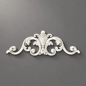
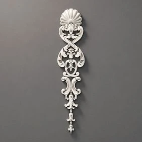
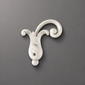
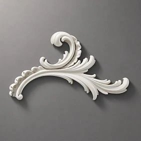
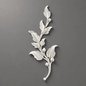
First, the internal area is calculated, and only then is NPU.VRS-018 placed.
For each panel variant, record at least six parameters: outer frame width, outer height, actual molding geometry, inner width, inner height, and center axis. If engineering elements are nearby, add constraint coordinates.
The calculation logic should proceed from the panel architecture to the decor, not the other way around. First, a stable frame is formed, then within it the zone is determined where the decorative element can be placed without conflicts.
This allows three different situations to be identified in advance. First: the element fits freely, with sufficient margins on all sides. Second: the element physically fits, but the margins are too small and the composition looks cramped. Third: the element does not fit — its contour intersects the molding, neighboring decor, or a functional point.
In the second and third cases, there is no need to "rescue" the standard scheme at any cost. A serial project actually benefits from complex panels being separated into distinct types. If a narrow edge frame does not allow the composition to be preserved, the correct solution may be to create a different module or to omit NPU.VRS-018 on that panel.
This approach seems more labor-intensive at the layout stage, but it saves time during ordering and installation: problematic geometry is solved once in the project, not eighteen times on site.
Get Consultation
What to record for NPU.VRS-018 in the specification
The entry "stucco decor — 18 pcs." is insufficient for a project with multiple decorative elements. During kitting, items with similar purposes are easily confused, especially if different overlays from the same collection or several polyurethane stucco items are used simultaneously on site.
For NPU.VRS-018, the working list should record the exact SKU, product name, material, size as stated in the current card 196 × 196 × 14 × 265 mm, panel type, number of elements per module, number of modules of this type, calculated total quantity, object zone, and project version.
If a project goes through several approval stages, it is useful to add a "status" column: preliminary, approved, changed, ready for order. Then an early estimate will not be accidentally mistaken for the final purchasing list.
You should not shorten the size to a single figure just because one of the dimensions is emphasized in the card name. For purchasing and verification, it is better to carry over the full size record, and additionally check the geometric outline against visual material or a sample.
An exact specification links the design solution to a specific product and eliminates the situation where a "similar overlay" arrives for installation because the order request did not include the SKU.
Why the SKU matters more than the words "decorative overlay"
On site, colloquial names inevitably become simplified. The designer says "central decor," the foreman says "large overlay," and the procurement specialist says "molding for frames." As long as only one sample is involved, everyone can understand each other. But once several similar items appear, such labels stop being reliable.
SKU NPU.VRS-018 serves as an unambiguous identifier. It must run through the project specification, order, labeling, and acceptance. Then the wording "central decor" remains a convenient explanation, but does not replace product identification.
This is especially important for series purchasing. An error in one item can affect several rooms at once. If a similar model is ordered instead of the required element, the problem will be discovered not on one panel, but across the entire batch.
Therefore, the rule is simple: in the text part of the project, clear names may be used, but in the specification and order the product must have an exact SKU. If the design changes, it is not the description such as "larger decor" that must be changed, but the specific specification line.
Marking out a symmetrical composition starts from the axis of the panel
If NPU.VRS-018 is used as the central accent inside a rectangular frame, its position is better set relative to the axes, not from a random edge of the wall. The wall may be uneven, the end module may have a modified width, and the molding may have slight installation deviations. The central axis of the approved panel itself remains clear reference geometry.
- Determine the actual inner contour of the frame.
- Find the vertical center axis of the panel.
- If necessary, determine the horizontal axis or the design height of the decor center.
- Determine the axis of the NPU.VRS-018 itself according to the approved template.
- Align the reference lines.
- Check the top, bottom, and side margins.
- Check for conflicts with engineering points and adjacent parts.
- Transfer the approved coordinates to the installation template.
| Inspection | What we record |
|---|---|
| Vertical axis | center of the approved frame or another axis specified by the design |
| Height | coordinate of the NPU.VRS-018 center relative to a stable base |
| Side margins | verified distances to the molding |
| Orientation | same element orientation for this type |
If the design intentionally shifts the element up or down, this does not cancel the axial system. Instead of the geometric center, a specific dimension is used: for example, the distance from the top inner edge of the frame to the element's reference axis. This dimension can be repeated across the entire series.
Why identical panel height does not make them the same type
Suppose a project has two frames 800 mm high. The first is 500 mm wide, the second is 650 mm wide. If you look only at the height, you might decide that this is one type and the decorative element is placed the same way.
But with central placement, the horizontal free space will be different. In a narrow frame, NPU.VRS-018 may be perceived almost as filling, while in a wide one it appears as a small central accent. Even with the same vertical coordinate, these are two different compositions.
A panel type is determined not by a single dimension, but by a set of characteristics: the outer and inner geometry, the frame profile used, the number of NPU.VRS-018, the position of the element, the presence of adjacent decorative details, engineering constraints, and the relationship to the door, furniture, or corner of the room.
If these parameters differ, it is better to create a separate type, even if two panels match in height. This makes the schedule a few lines longer, but it eliminates ambiguity on site.
Instead of eighteen separate frames, create several panel types
Suppose a project includes 18 decorative panels: 8 panels measuring 500 × 800 mm, 6 panels measuring 650 × 800 mm, and 4 panels measuring 400 × 650 mm. If each one is counted separately, the project quickly turns into a set of local solutions. It is much more convenient to create types A, B, and C.
| Type | Nominal size | Number of panels | Decoration layout |
|---|---|---|---|
| Type A | 500 × 800 mm | 8 | 1 × NPU.VRS-018 |
| Type B | 650 × 800 mm | 6 | 1 × NPU.VRS-018 |
| Type C | 400 × 650 mm | 4 | layout is determined separately |
Now the designer needs to fully approve three modules instead of eighteen independent instances. If all eight Type A panels are indeed identical, the same dimensions, axes, and decoration count are automatically repeated eight times.
This is exactly what serial logic is built on: one approved module → a known number of repeats → an accurate bill of materials.
But a type cannot be assigned based on the label on the plan alone. Before ordering, it is worth checking that the actual edge conditions do not break repeatability. A panel by a door or column may be labeled A on the drawing, but after an actual measurement require a separate version.
Everything for construction and renovation: first the reference module, then the series
When everything for construction and renovation is being purchased for a project, the temptation to order the entire repeating decorative series at once is understandable: the number of panels is known, the article number is chosen, the estimate is approved. But for decor whose position is critical to the composition, it is safer to first confirm one reference module.
The sequence is simple: one panel → full-size layout → check → approval → series repetition.
The reference does not necessarily have to be a fully finished painted wall right away. At an early stage, a full-size marking with a frame outline and the NPU.VRS-018 template is enough. It answers geometric questions: does the element fit, where is its center, is there enough free space, is it too large or too small relative to the field.
After that, a physical sample or test panel allows you to evaluate what a paper scheme does not show: relief, real shadows, visual weight, interaction with the molding and the final finish.
Only after the reference has been confirmed does it make sense to mechanically replicate the module. Then seriality becomes an advantage: instead of eighteen design decisions, one confirmed decision is executed the required number of times.
A full-size paper template should be made before purchasing the series
One of the cheapest ways to check the scale is a 1:1 template. Its task is not to imitate the relief of polyurethane stucco molding, but to show the actual occupied area.
The template must reproduce the outer contour of the product as accurately as the source data allows. It is not enough to print a 196 × 196 mm square if the actual product dimension record also includes a parameter L = 265 mm and the real shape extends beyond the conventional square. For verification, you need the actual overall contour, not a convenient simplification.
Next, the template is placed into the full-scale frame layout. Check the overall scale of the element relative to the panel, the free space along the edges, the position of the central axis, the mounting height, the relationship to adjacent frames, visibility from the main points of the room, and conflicts with furniture, doors, sconces, and switches.
Paper will not show the depth of the relief, the character of the shadows, or the quality of the joint with the surface. Therefore, the template is a geometric check, not a replacement for a physical sample.
But geometric errors are the most unpleasant to discover after purchasing a series. If the element no longer fits into a narrow frame, a beautiful relief will not fix the situation.
What can and cannot be assessed using a template
Using a full-scale template, you can assess the size of the occupied area, the center and axes, the offsets, the symmetry, the relationship to the frame, the proximity to functional points, the repeatability of several panels, and the need to designate a separate type.
Using a paper template, you cannot reliably assess the actual depth of the relief, the shadows under side lighting, the surface texture, the quality of the finish, the three-dimensional junction with the molding, or the final perception after installation.
If, after the paper check, the scale is in doubt, the next step is one physical element and one mock-up section. There is no need to buy the entire series at once just for verification.
This two-stage control separates the tasks: the paper template cheaply rules out geometrically incorrect solutions, while the physical sample confirms the aesthetic and installation nuances.
The molding and NPU.VRS-018 should be considered as a single composition
In the current NPU.VRS-018 product page, the related items section shows primed MDF moldings MLD-003-MG and MLD-002-MG. This is a useful product suggestion, but it must not be turned into a statement that any frame made from these profiles is automatically sized for NPU.VRS-018.
The "Customers also buy" block and the architectural specification serve different purposes. For a specific wall, the outer frame size, the inner clear opening, the visual width of the molding, the depth and relief of both elements, the corner joints, the distance from the overlay to the profile, the overall style, and the future finish system are checked separately.
Therefore, the correct wording is this: MLD-003-MG and MLD-002-MG are shown on the product page as related products, but the specific frame must be designed and checked against dimensions separately.
For the customer, this is more practical than a declaration of automatic compatibility. They understand which items can be considered together, but they do not skip the calculation step.
Mini-specification for each panel type
After approving the geometry of each type, create a small bill of materials. It links the visual diagram to the actual products and quantities.
| Component | Type A | Note |
|---|---|---|
| NPU.VRS-018 | 1 pc. | central decorative element |
| upper section of the molding | According to the drawing | actual length after approval of the joints |
| lower section of the molding | According to the drawing | actual length |
| side sections of the molding | According to the drawing | Two sides |
| number of type A panels | 8 | according to the current plan |
If type A changes, one module card is adjusted and the entire series is recalculated. There is no need to search for eight identical rows across different rooms. For type B, a separate schedule is created, even if NPU.VRS-018 is used in the same quantity: it may have a different frame width or a different control height.
The quantity of NPU.VRS-018 is calculated by module types
Once the types are approved, the calculation becomes simple. Suppose type A is 8 panels with one NPU.VRS-018 each; type B is 6 panels with one each; type C is 4 panels with two elements each.
Type A: 8 × 1 = 8 pcs.
Type B: 6 × 1 = 6 pcs.
Type C: 4 × 2 = 8 pcs.
Total: 22 pcs. NPU.VRS-018.
| Panel type | Number of panels | NPU.VRS-018 per panel | Total |
|---|---|---|---|
| A | 8 | 1 | 8 |
| B | 6 | 1 | 6 |
| C | 4 | 2 | 8 |
| Total | 18 | 22 |
This example shows why the formula "18 frames = 18 overlays" is incorrect. The object indeed has 18 panels, but the approved modular scheme requires 22 elements.
If an element is used in pairs, it must be a separate module type
The paired arrangement of NPU.VRS-018 cannot be handled as a manual correction in the order's total line. If type C contains two elements, this must be recorded in its specification: "2 pcs. per panel."
Otherwise, hidden logic arises. The summary table will show 18 panels, someone will manually add four items, and the total of 22 will be mathematically correct but inexplicable. The next time the number of panels changes, the manual addition will easily remain unchanged.
The modular model eliminates this problem: total quantity = sum across all types (number of panels of the type × number of elements per panel).
For types with two elements, the relative position of the pair must also be defined: the distance between centers, the common axis, the vertical coordinate, the ornament direction, and symmetry. You cannot simply specify "two decors" and leave it to the installer to arrange them at their discretion.
If a paired scheme is used in only one room, it is still a separate type. The repeat count may be one — the typification remains useful because it fixes a distinct composition and prevents it from dissolving into notes.
Repair products are calculated wholesale by modules, not by wall area
When purchasing materials for renovation in bulk, it is customary to work in square or linear meters. For tiles, area matters; for many profiles, length matters. But the decorative moulding element NPU.VRS-018 is counted per piece, and the room's area alone says nothing about the quantity.
A wall with an area of 40 m² may have four large decorative panels or twenty narrow ones. In the first case, one quantity of overlays will be needed; in the second, a completely different one. That is why the basic formula for such a product looks like this: number of modules × number of elements in one module.
The wall area is involved only indirectly — through the architectural layout. First, the project determines the number of frames and their types, and only then does the quantity of NPU.VRS-018 follow from them.
This is a good example of why different units of measurement should not be mixed within a single “decor” line. Moulding is calculated by frame lengths and product units of the profile, NPU.VRS-018 — in pieces, paint or another material — by its own norm. Each group has its own method.
For a large purchase, you can use the link to construction and repair goods wholesale as a general entry point to the STAVROS assortment, but within the project specification, precise product lines and units of measurement are still required.
The quantity of overlays and the quantity of moulding are calculated in different ways
One frame combines NPU.VRS-018 and moulding visually, but from a purchasing standpoint these are two different tasks.
NPU.VRS-018 is counted by the number of elements in the approved modules. Moulding is counted by the geometry of each frame, the lengths of the sides, the joining method, the product length of the profile, and the accepted cutting allowance.
If everything is combined into a conventional line “decor — 120 meters,” the overlays will disappear from the calculation as piece items. If, conversely, the moulding is counted “per frame,” the lengths and cutting will be lost. The bill of materials must preserve different units of measurement, even if the products are part of one composition.
| Module code | Position | Unit | Calculation principle |
|---|---|---|---|
| A | NPU.VRS-018 | pcs. | quantity per module × number of modules |
| A | molding of the selected article | per product unit | perimeters, cutting and approved allowance |
This way the designer composition remains unified, and each product group is calculated using the correct method.
The series needs a single reference dimension that cannot be interpreted differently
Even if the central axis is clear, the installer needs a numerical reference point. For example, the project can fix the distance from the upper inner edge of the frame to the center of NPU.VRS-018. Let's designate it as X.
For type A: X = the design value for all eight type A panels. Now the position is not defined by the words "slightly above the middle." It is reproduced by measurement.
The reference dimension is chosen so that it can actually be transferred to the site. If the upper edge of the frame is not yet installed, anchoring to it is useless at an early stage. In that case, the base horizontal of the room or another confirmed reference can be used. But in the final installation drawing, all dependencies must be unambiguous.
For type B, the X value may be the same or different — this is a design decision. The coordinate cannot be transferred automatically just because the panel height matches. A paired composition will require additional dimensions: the distance between centers and the position of the pair's common axis.
The larger the series, the more valuable such reference dimensions are: once approved, they prevent the accumulation of small visual deviations.
An installation template turns the approved drawing into a repeatable result
After the module is approved, it is useful to prepare an installation template or a clear dimension map. Its purpose is not to replace professional marking out, but to remove the need to make design decisions again on each panel.
The template can fix the vertical axis of the panel, the horizontal reference line, the center of NPU.VRS-018, reference offsets, the orientation of the product, the panel type code, and the number of the current drawing version.
On a series of eight identical panels, this is especially useful. After the first installation is checked, the following ones are carried out using the same coordinate system.
But the template must be tied to the actual panel. If the installation of the frames has produced a systematic offset relative to the design, it makes no sense to blindly transfer the decor according to the old mark. First the base geometry of the series is checked, then the template is used.
Repeatability works only with a repeatable base. If the frames themselves turned out different, the decorative template will not fix the problem automatically.
The end panel near the door is often not a standard one
Typification should not force reality to conform to a neat table. Edge panels near doorways, corners, columns, and built-in furniture often differ from the central modules.
Suppose eight type A panels run along the main wall. A narrower section remains by the door. The worst strategy is to automatically "compress" type A to the new width, preserving NPU.VRS-018 and all elements at any cost.
Instead, a separate type is created, for example type D — an edge panel. For it, the free field, the scale of NPU.VRS-018, the central axis, the relationship to the door casing, the visual fields, and the very necessity of the central decor are re-checked.
Perhaps the best option is to leave only the frame without the central overlay. Perhaps a different decorative element is needed. Perhaps the width of the wall modules should be redistributed earlier so that the edge panel does not become too narrow. The main thing is not to pass off a deformed module as a standard one.
One module cannot be forced to work in any geometry
In serial design, it is easy to fall into a trap: once type A is approved, you want to use it everywhere. But a module has a scope of applicability. If the free field becomes too narrow, fitting may destroy the proportions.
Let's imagine that on a standard panel, after installing the frame, comfortable fields remain around NPU.VRS-018. On the edge panel, the free width is noticeably smaller. Technically, the element still fits, but only a few millimeters of visual air remain on the sides.
Formally, there is no intersection, but the composition looks random and cramped. This is the case when a mathematical "fits" does not equal a design "suitable."
Therefore, for each type it is useful to establish not only a condition of physical placement, but also a criterion of the approved composition. It cannot be reduced to a universal number for all projects: the required offset depends on the scale of the frame, the profile, and the visual language of the interior. The decision is confirmed on the mockup.
If a type does not pass the check, there is no need to reduce the fields to an arbitrary minimum. Create another module.
Before approving the template, switches, sockets, wall lights and other engineering elements are checked
Decorative symmetry exists within a real interior where functional points already exist. Switches, sockets, thermostats, wall lights, control panels, intercoms, cable outlets and furniture can limit the free area more than moulding.
Situations are especially dangerous when the engineering is shown on one set of drawings and the decorative layout on another. In the visualisation the wall looks perfect, but on site the switch ends up inside the ornament zone.
Before approving the module, you need to overlay the actual wall geometry, the frame, the NPU.VRS-018 outline, the coordinates of engineering elements and large pieces of furniture or light fixtures if they affect the composition.
If the switch is already rigidly fixed by the engineering design, the decorative scheme is built around it. Moving a functional point for the sake of symmetry is possible only as a separate agreed decision, not as an installer's assumption.
The order is simple: first the real constraints, then decorative symmetry within the available space.
The last frame in the row often changes the final quantity of NPU.VRS-018
While the wall exists only in concept, it is easy to divide it into conditionally equal modules. After precise measurement it turns out that the clean length does not divide by the chosen step without a remainder. Edge fields, a doorway, a pier or the need to preserve an axis relative to the furniture appear.
Because of this, the last frame may become a standard one, become wider, disappear, split into two other modules or get a separate type without NPU.VRS-018.
Consequently, the final quantity of decorative elements cannot be approved before the entire wall is laid out. If 18 frames were initially planned, and after the working measurement one edge panel is excluded, the purchase changes. If instead of one wide frame two narrow ones appear, the quantity may increase — but only if both new panels pass the compositional check.
That is why the bill of materials must reference the current version of the plan, not the earlier figure of "18 panels" from the concept.
For a large series, first produce one real panel
A full-size paper layout verifies the geometry. But if the series is large, before final replication it is useful to produce one real module or at least a mock-up section.
On it, one evaluates the scale of NPU.VRS-018 in volume, the real relief, shadows from side and top light, the relationship of the overlay to the molding profile, the quality of the chosen height and axis, the nature of the junction to the wall, and the visual result after preparation and finishing.
If the mock-up is approved, its status is recorded as the reference module. For a series, this is more important than the verbal instruction to "do it as in the visualization." The installation team then has a physically verified result and a dimensional diagram.
If a problem is discovered, changing one panel is cheaper than redoing eighteen. Therefore, a trial module is not a waste of time, but insurance against replicating an error.
NPU.VRS-018 and the molding must have a coordinated finishing system
If the central decor and the frame are conceived as a single architectural solution, their finish must be coordinated by the project. This concerns not only color, but also the degree of gloss, the visual uniformity of the surface, and the preparation of the joints.
At the same time, the article on series calculation should not turn into a separate guide to painting polyurethane and MDF. For the procurement and project task, a few principles are sufficient.
The method of final finishing must be known before the reference is approved if it noticeably affects the appearance. A physical mock-up is best evaluated in a state as close as possible to the future interior. One cannot assume that the same color automatically makes different reliefs visually unified — light and the depth of the profile also participate in perception.
If the project calls for contrasting accentuation of NPU.VRS-018, this is also recorded in the panel type card so that installation and finishing do not interpret the composition differently.
Order acceptance: verify SKU and quantity, not just boxes
A serial purchase may arrive in multiple packages. The number of boxes alone does not confirm completeness. During acceptance, line items are verified.
For NPU.VRS-018, the control line looks like this: SKU NPU.VRS-018 → quantity per the approved schedule → actually accepted → discrepancy.
If a project uses several different NPU positions, they cannot be combined into a single line “moulding — 40 pcs.” The total quantity may match, even though a specific article will be missing.
| Article | By order | Accepted | Difference |
|---|---|---|---|
| NPU.VRS-018 | 22 | 22 | 0 |
| another NPU position | 18 | 18 | 0 |
Additionally, the condition of the items is checked within the accepted acceptance procedure. If there is damage or a discrepancy, it is better to record it before distributing the elements to the rooms.
Zone marking links warehouse completeness with the project
If all 22 NPU.VRS-018 are used identically, they can be stored as a single product batch. But on a complex site, it is useful to immediately allocate the quantity by types and zones.
| Zone | Panel type | Number of panels | NPU.VRS-018 |
|---|---|---|---|
| Lobby | A | 8 | 8 pcs. |
| Corridor | B | 6 | 6 pcs. |
| Restaurant | C | 4 | 8 pcs. |
This way, the assembler sees not only the total quantity of 22, but also the purpose of the parts of the batch. If installation is carried out in stages, a set can be prepared in advance for each zone.
Marking is especially useful when types use different numbers of elements. Without it, eight items intended for four double panels of type C are easily perceived as a reserve for eight single frames.
How to account for reserve and not turn it into a random number
For individual decorative elements, the question of reserve is decided separately from the base quantity. First, the exact requirement is calculated according to the approved modules. In our example, this is 22 NPU.VRS-018. Only after that does the project or purchaser decide whether an additional reserve is required and on what basis.
Reserve should not be hidden inside the calculation. The entry "order 24" is worse than the entry: calculated requirement — 22 pcs.; additional reserve — 2 pcs.; total to order — 24 pcs. The second scheme shows where the additional items came from. If the order is revised, the reserve can be discussed separately.
There is no universal percentage for all projects. The decision depends on cost, availability of reordering, risk of damage, deadlines, complexity of the site, and the accepted procurement policy. If there are no grounds for a reserve, there is no need to artificially add it "just in case."
It is important not to confuse product reserve with a calculation error. Reserve should not compensate for an unknown number of panels. First, the modules and quantity are approved, then the reserve is discussed.
What to do if the number of panels changes after ordering
Changing the project after placing an order is a common risk of a long renovation. For example, instead of four panels of type C, three remained, and an additional panel of type A appeared in another zone.
The recalculation must follow the same modular formula: new quantity = sum (new number of modules of each type × NPU.VRS-018 per module).
Do not adjust the final quantity manually without changing the source type table. Otherwise, after several iterations, no one will be able to reconstruct the order logic.
Example: type A was 8, became 9 — plus one NPU; type B unchanged; type C was 4, became 3 with two NPUs per panel — minus two NPUs. The total requirement decreases by one element. If the item has already been ordered, the difference becomes a potential reserve or requires a different decision depending on the delivery stage.
Such a recalculation takes minutes if the type system is preserved. With a general list of “18 panels, 22 decors,” a change quickly turns into a manual check of the entire project.
How to check the series for hidden differences before the final order
Before issuing the “to order” statement, it is useful to go through not only the type table but also the room plan. It may reveal panels that are formally assigned to one type but have other restrictions.
- Compare the actual width and height of each panel with the type.
- Check whether the frame profile is the same.
- Find panels with a switch, sconce, or other exception.
- Check the adjacenc