Article Contents:
- Wooden ceiling plinth PLT-001: which parameters to use in the calculation
- Why you cannot calculate "distance to the hatch minus 120 mm"
- Ceiling plinth near a removable cover: why service access matters more than perfect continuity
- When it is better to end PLT-001 before the service hatch
- Ceiling plinth made of natural wood near the service hatch: is an expansion gap needed
- Ceiling hatch with a hinge at the wall and a hinge away from the wall — two different scenarios
- Sliding ceiling panel: why PLT‑001 needs to be checked on a different principle
- Why the service test needs to be repeated after installing PLT‑001
- Why saving one PLT‑001 strip can increase the number of visible joints
- How to calculate the profile return near the hatch in the total length
- How to check whether the PLT-001 fastener overlaps the hatch frame
- What to do if the hatch is already installed not parallel to the wall
- Wooden ceiling plinth and stretch ceiling with a service hatch
- How to make a control drawing of the "wall — PLT-001 — hatch" joint
- If the hatch is located above a tall cabinet
- If PLT-001 needs to be interrupted on both sides of the hatch
- Final technical specification of the joint before payment
- Minimum linear meters versus minimum visible joints: two different estimates
- Service hatch near an external corner: double cutting risk
- Short conclusion
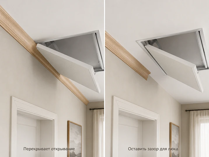
A ceiling service hatch is already planned near the wall. It needs periodic access to a filter, valve, ventilation equipment, electrical components, or another unit. At the same time, the room is to be finished with a natural wooden profile PLT-001 along the wall-ceiling line. In such a situation, the purchase decision cannot be based solely on the distance from the wall to the hatch edge.
Even if the lid does not statically overlap the plinth, it may hit it when opening. Even if the lid opens, after installing the profile it may become impossible to remove it entirely, reach in with a hand, pull out the filter, or turn a tool. Conversely, a small gap to the hatch does not necessarily mean PLT-001 must be interrupted—first, the actual ceiling projection of the profile and the trajectory of the specific lid need to be determined.
Therefore, the direct answer is:
PLT-001 can be purchased and installed near the service hatch only after four checks: the distance from the wall to the hatch, the actual projection of the profile onto the ceiling, the kinematics of the lid, and the required service access after opening. Parameter A = 120 mm cannot be automatically considered the distance the plinth will extend onto the ceiling.
Practical procedure before payment:
-
measure the distance from the wall to the nearest fixed edge of the hatch frame;
-
obtain drawing PLT-001 and determine the actual working projection of the profile onto the ceiling;
-
open the hatch to the full working angle and trace the trajectory of the nearest edge;
-
check not only opening, but also removal of the cover, hand access, and extraction of the serviced equipment;
-
make a rigid template of the actual profile;
-
temporarily install it on the line of the future PLT-001;
-
repeat the full service cycle;
-
decide: run the profile continuously, end it before the hatch, or choose a more compact cornice;
-
only after this, build the cutting map for slats 2400 mm long.
For a general selection, you can to buy wooden baseboard after comparing dimensions. If PLT-001 itself is already approved by style, proceed to buy the wooden ceiling plinth PLT-001 should be done after checking the hatch with a physical template.
Wooden ceiling plinth PLT-001: which parameters to use in the calculation
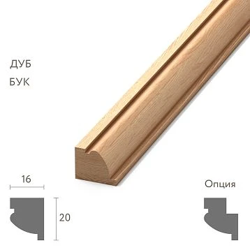
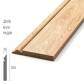
For this task, only confirmed parameters of the current main PLT-001 version are needed:
| Parameter | PLT‑001 | Why it is needed next to the hatch |
|---|---|---|
| Article number | PLT‑001 | Do not mix with PLT-001-1 |
| A | 120 мм | Cross-section size, but not a ready guarantee of ceiling projection |
| C | 15 мм | Second profile dimension |
| L | 2400 мм | Cutting map and number of slats |
| Material | Oak | Natural wood |
| Quality | Prestige | Surface preparation |
| Preparation | For enamel | Consider fresh ends after trimming |
| Purpose | Ceiling skirting board | Works in the upper wall contour |
Key technical point — size A = 120 mm. It confirms the profile dimension per the card, but does not prove that the installed PLT-001 will cover exactly 120 mm on the ceiling. The ceiling profile has a shape and working position in the corner. We need two real projections:
-
how much the profile occupies along the wall;
-
how much does it take up on the ceiling.
It is the ceiling projection that determines whether PLT-001 will approach the hatch frame.




Why can't we calculate "distance to hatch minus 120 mm"
Let's imagine that the nearest edge of the hatch is 150 mm from the wall.
Naive scheme:
150 − 120 = 30 mm of clearance.
It is correct only under one condition: the drawing confirms that the working ceiling projection of the profile is indeed 120 mm. If A describes a different dimensional coordinate of the cross-section, the conclusion is incorrect.
Therefore, in the article we use the notation:
P = actual ceiling projection of the installed PLT-001.
It is obtained:
-
from the drawing;
-
from a physical sample;
-
from a rigid profile template in the actual installation position.
Before this, the value P is unknown.
Why thickness C = 15 mm is also important
Parameter C does not replace the projection, but affects:
-
profile volume;
-
edge near the hatch;
-
end processing;
-
possible contact with the lid in motion.
With a complex trajectory, the lid may pass not near a flat line, but near the protruding relief of PLT‑001.
Length 2400 mm is a commercial parameter
After resolving the hatch assembly, not only installation changes, but also procurement. If the profile has to be interrupted, a long wall turns into two separate segments. Sometimes this allows using the remainder. Sometimes, on the contrary, it creates an extra visible joint and requires an additional full plank.
Therefore, the quantity is calculated after determining the end point at the hatch, not by the abstract perimeter of the room.
Our factory also produces:



Before purchasing PLT‑001, not one gap is measured, but four values
For a technically correct solution, a small map of the assembly is sufficient.
Let us denote:
-
D— distance from the wall to the nearest fixed edge of the hatch; -
P— actual ceiling projection of PLT‑001; -
H— geometry of the lid/frame in the movement area: thickness, protrusion, hinge position; -
C(α)— minimum clearance between the moving cover and the future profile at the opening angleα.
1. D — distance from the wall to the hatch edge
Measure not "approximately along the ceiling," but at several points:
-
at the left edge;
-
in the center;
-
at the right edge.
If the frame is not parallel to the wall, the distance may vary.
The calculation uses not the average, but the critical point.
2. P — actual ceiling projection of the profile
This is the most underestimated dimension.
Until it is known, it cannot be determined whether PLT-001 enters the hatch zone or not.
Static clearance between the profile and the fixed frame:
S₀ = D − P.
If S₀ ≤ 0the profile physically intersects the frame line, and continuous installation without changing the node is impossible.
If S₀ > 0this is only the first check. The cover still needs to pass in motion.
3. H — cover and frame
You need to see:
-
where the hinge is located;
-
cover thickness;
-
Does the frame protrude?
-
whether the cover edge extends downward or toward the wall;
-
whether an offset is required first, and then a rotation.
Two hatches of the same size can have completely different kinematics.
4. C(α) — dynamic clearance
Compatibility condition:
C(α) > 0 along the entire working trajectory,
taking into account the actual installation and required service space.
The article intentionally does not assign universal 3, 5, or 10 mm. The hatch manufacturer, the actual hinge, and the service operation matter more than an arbitrary "norm."
Why distances D and S₀ are insufficient
Let PLT‑001 not reach the fixed frame by 20 mm.
The cover may when opening:
-
move toward the wall;
-
turn with the outer corner toward the profile;
-
first shift, then lower.
Then static 20 mm do not guarantee passage.
Get Consultation
Wooden baseboard and folding ceiling hatch: where the real conflict occurs
The flip lid has several different collision scenarios.
The profile physically overlaps the frame.
The simplest case.
If P ≥ D, the future PLT-001 overlaps part of the frame or opening.
Solutions:
-
finish the profile earlier;
-
choose a different profile;
-
change the decorative scheme.
You cannot simply cover part of the service frame with wood if it needs to be removable or serviceable.
The profile does not extend into the opening, but prevents the lid from rotating.
This is a typical dynamic error.
In the closed position, everything looks correct.
At the first few degrees of opening, the nearest corner of the lid moves along an arc and touches the decorative relief.
That is why the test is performed slowly across the full range of angles, not just in the "closed/fully open" position.
The lid opens but hits PLT‑001 before reaching the working angle
For example, the hatch must open wide enough to:
-
stay open;
-
allow access for two hands;
-
allow the filter to be removed.
If the lid only opens partially after profile installation, the hatch formally "works," but the service function is compromised.
The lid opens, but it cannot be removed
A removable or combined lid may require:
-
lifting;
-
tilt;
-
take out of the loops.
A continuous profile nearby can cover exactly this additional path.
It is impossible to remove the equipment through the hatch.
The final check is not the cover, but the serviced item.
If there is a filter 400–500 mm long behind the hatch, the cover must not only open: the filter must pass along its trajectory.
There is no universal size here. The service operation needs to be reproduced.
Ceiling plinth next to a removable cover: why service access is more important than perfect continuity
A decorative contour around the perimeter looks better without breaks, but a ceiling hatch exists not for decoration.
If the cover needs to be completely removed for maintenance, it is better to have a neat ending of PLT‑001 at a clear point than a beautiful continuous line that has to be dismantled during every repair.
What to check for the removable cover
-
How the cover is released from the retainers.
-
In which direction the first shift goes.
-
Where the edge closest to the wall goes.
-
How the cover is held with hands.
-
Can it be taken out of the opening without contact with the profile.
If the cover is removed upward and toward yourself
Space is needed above and in front of the edge.
If the cover comes out by lateral displacement
Horizontal freedom near the wall is critical.
If the cover is held by a safety cable
We still need to check whether the cable forces the cover to rotate specifically toward PLT-001.
How to make a PLT-001 template before ordering a full batch
The most reliable way is to reproduce the actual working cross-section, not just stick a 120 mm wide strip of paper to the ceiling.
Option 1. Template from a drawing
If the drawing provides a contour, it is transferred to:
-
thick cardboard;
-
plywood;
-
MDF;
-
rigid plastic.
The template must replicate the working position of the profile in the corner.
Option 2. One physical fragment
It is even more reliable to attach the actual PLT-001.
It shows:
-
actual relief;
-
actual depth;
-
shadow;
-
position of the point closest to the hatch.
How to test
-
Place the template against the wall.
-
Secure without damaging the ceiling.
-
Close the hatch.
-
Open slowly.
-
Check the first degrees.
-
Bring to full working angle.
-
Remove the cover, if provided.
-
Run hand/tool over it.
-
Remove the part being serviced or its mock-up.
Why can't 120 mm simply be subtracted from the distance to the hatch
Because the mock-up must show P, not a conditional A.
After the template, you can already write specifically:
D = ___ mm
P = ___ mm
S₀ = D − P = ___ mm
and separately the result of the dynamic test:
the cover passes / does not pass.
When a wooden ceiling plinth can be run continuously past the hatch
A continuous line is acceptable if several conditions are met simultaneously. One "visually passes" is not enough.
The profile does not intersect the frame
Statically:
D > P.
But this is only basic geometry.
The cover passes freely along the entire trajectory
There must be no contact:
-
at the beginning of opening;
-
in the middle;
-
in full working position;
-
when closing.
Cover removal is preserved
If the service instruction provides for complete removal, it must actually be performed with the template installed.
Access to fasteners and latches is preserved
PLT-001 must not cover:
-
screws;
-
magnetic retainers;
-
latch;
-
safety elements;
-
service frame.
Access to equipment is preserved
This is the most important criterion.
If a filter, valve, or unit can only be serviced at a specific cover angle, the continuous profile must allow exactly that mode.
The joint of the PLT-001 itself does not fall into the critical zone.
Even if a single solid plank fits, joining two planks near the hatch can:
-
create an additional protrusion;
-
require sanding/gluing near the frame;
-
visually emphasize the service point.
It is better to decide in advance where the nearest visible joint will be.
When it is better to end PLT-001 before the service hatch
Sometimes interrupting the profile is a professionally cleaner solution.
The hatch is located too close to the wall
If the actual projection P almost reaches the frame, there may be no dynamic clearance.
The cover opens toward the wall
Then the nearest corner moves toward the profile.
The hatch must be completely removed
Additional space is more important than the continuity of the cornice.
A large element is removed through the opening
If the filter or equipment needs to be turned near the wall, the profile can become an obstacle even with the cover free.
The hatch frame must remain serviceable
If the manufacturer provides for removal of part of the frame, PLT-001 must not be applied over it.
A narrower profile solves the joint much more cleanly
Then there is no point in forcibly using PLT-001 just because it is chosen on other walls.
Sometimes the right architecture is to run PLT-001 along the main part of the room, and near the technical area switch to another element or end the line earlier.
How to finish the oak PLT-001 near the hatch
The ceiling plinth cannot be interrupted with a random unprocessed cut.
For the oak profile, the visible end becomes part of the interior.
Straight end
The simplest option.
Required:
-
precise cross-cut;
-
sanding;
-
end finishing;
-
absence of relief chipping.
Returning the profile to the wall
A short piece covers the cross-section and visually "returns" the cornice to the wall.
Advantages:
-
the profile looks finished;
-
the open cut is not visible.
Disadvantages:
-
more complex cutting;
-
an additional short element is needed;
-
the number of miter joints increases.
Short decorative transition
Possible if nearby there is:
-
a vertical panel;
-
column;
-
portal;
-
another wooden element.
But such a transition should be part of the project, not a disguise for a bad cut.
Why you cannot leave an untreated oak end grain
A fresh cut differs:
-
the color;
-
by absorption;
-
by texture;
-
by gloss after finishing.
Even if PLT-001 is painted with an opaque enamel, the end grain after trimming requires preparation in the same system.
The end grain should be designed before the main finish
Correct sequence:
hatch assembly → end point → cut → dry fit → end grain treatment → finish → installation.
Not the other way around.
Ceiling molding made of natural wood near a service hatch: is a compensation gap needed
For natural wood, it is important to consider geometric stability, but the article should not invent a universal "3 mm gap."
The actual service joint depends on:
-
hatch design;
-
hardware;
-
widths and shapes of the cover;
-
working trajectory;
-
installation method of PLT-001;
-
humidity conditions of the room;
-
the finish coating;
-
tolerance of a specific door/frame.
What needs to be obtained instead of a random number
-
Manufacturer's requirement for the hatch regarding free space.
-
Actual test with a template.
-
Check after final finishing.
-
Re-check after several opening cycles.
Why a too-small service seam is bad
-
the cover may catch;
-
the finish gets damaged quickly;
-
it is impossible to remove the panel;
-
the slightest deformation turns into contact.
Why a too-large seam is also not always good
If the hatch is located in a front area, a wide random gap next to an expensive oak profile looks technically unfinished.
Therefore, mechanics are ensured first, then the appearance is optimized.
A ceiling hatch with a hinge at the wall and a hinge away from the wall — two different scenarios
The hinge position fundamentally affects the conflict.
The loop is on the wall side
The nearest edge of the lid rotates almost around an axis located near PLT-001.
Depending on the design:
-
the edge may maintain its position;
-
the protruding corner may go toward the profile;
-
the lid thickness may enter the cornice area.
Such a scenario requires a particularly precise mockup.
The loop is on the opposite side
The edge closest to the wall may descend along a large arc.
The static profile is located far from the hinge, but in motion it is this edge that becomes critical.
Why a photo of a closed hatch does not answer the question
The photo only shows α = 0°.
A conflict can arise when:
-
5°;
-
20°;
-
45°;
-
before full opening.
Therefore, a dynamic test is needed.
Sliding ceiling panel: why PLT‑001 needs to be tested on a different principle
If the lid does not tilt open but slides, there is no arc. But another risk appears.
Space for linear travel is needed
If the panel slides toward the wall, PLT‑001 may end up directly in its path.
Space for capture is needed
The user should be able to:
-
press;
-
pull;
-
slide;
-
remove.
The guide needs to be checked
The profile should not cover:
-
fasteners;
-
stop;
-
the service gap.
Conclusion
For a sliding hatch, not only the distance to the edge is measured, but the full length of the working stroke towards the wall.
Why repeat the service test after installing PLT-001
Even a perfect template does not reproduce all real layers:
-
glue;
-
possible lining;
-
finish paint;
-
actual position of the bar.
Therefore, after installation but before final handover:
-
open the hatch;
-
close;
-
remove the cover, if provided;
-
take out the serviced element;
-
put everything back in place.
If the profile is already painted, the test is performed carefully, but not postponed "until the first annual maintenance".
How to join a wooden ceiling plinth at the nearest corner if the hatch changes the cutting pattern
The hatch often forces you to end a solid plank earlier than planned. Then the nearest internal or external corner starts to affect the purchase.
For example, from the internal corner to the end point at the hatch:
2350 mm.
PLT‑001 has a length of 2400 mm.
At first glance, one plank fits.
But you need to consider:
-
the actual corner cut;
-
trimming the factory end;
-
finishing the end at the hatch;
-
possible return.
That is, 50 mm of nominal remainder is a very tight margin.
How to make a corner on a wooden ceiling plinth
For a real room corner, its geometry is first measured.
If the angle differs from 90°, both pieces should not be automatically cut at 45°.
With a symmetrical miter joint, the angle of each piece is approximately half of the actual room angle, but the specific setting depends on the working position of the profile and the tool.
Why the ceiling profile is more complex than the floor one
PLT-001 works simultaneously with the wall and ceiling. Therefore, the position of the piece on the miter saw must replicate its installation orientation or be calculated according to the manufacturer's/craftsman's scheme.
How to join wooden ceiling plinth in corners without unnecessary risk near the hatch
-
First, make a test cut on the offcut.
-
Check the angle dry.
-
Only after this, cut the plank that fits to the hatch.
-
Do not use the last available piece without testing.
Why the hatch affects the angle
If a long plank ends at the hatch, the miter cut error is no longer compensated by shifting: the other end also has a fixed point.
In this case, useful length allowance is especially important.
PLT-001 2400 mm long: how much wooden ceiling molding to buy considering the hatch
Usual formula:
perimeter / 2.4 + 10%
too rough for a room with a service hatch.
A map of individual pieces is needed.
Example room
Suppose, after accounting for doors and technical gaps, the following ceiling profile segments are obtained:
-
4200 mm;
-
3600 mm;
-
2350 mm before the hatch;
-
1450 mm after the hatch;
-
2800 mm;
-
1750 mm.
Total length:
4200 + 3600 + 2350 + 1450 + 2800 + 1750 = 16,150 mm.
By pure linear footage:
16 150 / 2400 ≈ 6,73.
Mathematical minimum:
7 planks.
But this is not yet a finished order.
Why 7 may not give a beautiful cut layout
The 4200 mm segment requires at least two pieces.
3600 also requires two.
2800 — minimum of two.
2350 mm almost consumes an entire plank.
After this, short leftovers may not fit into the remaining 1450 and 1750 mm without additional joints.
Minimum length map
You can maximize the use of leftovers, even if some joints end up on visible walls.
Goal:
minimum of whole planks.
Map of minimum visible joints
Long central walls get the longest possible seamless sections.
Leftovers are directed:
-
above the cabinet;
-
into a short wall section;
-
into a less noticeable area.
Goal:
clean appearance, even if an eighth plank is needed.
Why the buyer needs to choose a priority
For an oak ceiling profile, the cost of an additional plank can be noticeable, but one extra joint on the main wall remains visible for the entire service life.
Saving material and quality of composition are different goals.
Why saving one PLT‑001 plank can increase the number of visible joints
Consider a wall of 4.7 m.
One scheme:
-
2400;
-
-
Two segments, one joint.
If remnants from other walls force you to do so:
-
1800;
-
1500;
-
1400,
The net footage is the same, but there are already two visible joints.
Where a joint is especially undesirable
-
in the center of the main wall;
-
in the area of side light;
-
right next to the hatch;
-
near the outer corner.
Where it is wiser to use the remnant
-
above built-in furniture;
-
on a short wall section;
-
in the curtain zone;
-
on the secondary wall.
Two specification options
Option A — minimum number of strips.
Maximum use of each leftover piece.
Option B — minimum number of joints.
Some leftovers remain as technical reserve, but long walls are cleaner.
For expensive finishes, it is often better to calculate both options first rather than automatically choosing the cheapest one.
How to account for the profile return near the hatch in the total length
If PLT-001 ends with a return to the wall, the short piece also requires material.
It cannot be considered equal to simply C = 15 mm.
The length depends on:
-
profile shape;
-
miter joint angle;
-
actual projection;
-
return method.
Where to get material
Usually from the remainder.
Therefore, it is useful to keep all short offcuts after corners until the service node is completed.
Why the return must be made before final painting
The first trial element may not match the profile pattern or angle.
Better to debug it on the technical remainder.
Two real cutting layouts for the same total length: 7 or 8 planks
For conditional segments:
-
A = 4200 mm;
-
B = 3600 mm;
-
C = 2350 mm;
-
D = 1450 mm;
-
E = 2800 mm;
-
F = 1750 mm;
the total length is 16,150 mm.
Seven PLT-001 planks give:
7 × 2400 = 16,800 mm.
Nominal total balance:
650 mm.
That is, by length, seven are indeed sufficient. But let's look at the visible connections.
Option A — 7 planks, maximum material usage
One of the possible cuts:
Slat 1: 2400 mm → wall A.
Slat 2: 1800 mm → completion of A; 600 mm → start of B.
Slat 3: 2400 mm → middle of B.
Slat 4: 600 mm → completion of B; 1800 mm → start of C.
Plank 5: 550 mm → completion of C; 1450 mm → wall D; 400 mm → start of E.
Plank 6: 2400 mm → completion of E.
Plank 7: 1750 mm → wall F; about 650 mm remains.
We get visible joints:
-
A — 1;
-
B — 2;
-
C — 1;
-
D — 0;
-
E — 1;
-
F — 0.
Total 5 joints.
Option B — 8 planks, fewer visible joints
Can be distributed differently:
-
A 4200 = 2100 + 2100;
-
B 3600 = 1800 + 1800;
-
C 2350 = as one piece;
-
D 1450 = as one piece;
-
E 2800 = 2350 + 450;
-
F 1750 = as one piece.
The 450 mm piece for E can be obtained from the same eighth board together with the 1750 mm piece:
450 + 1750 = 2200 mm.
Then eight slats are required, but visible joints remain only on the three walls that are physically longer than 2400 mm:
-
A — 1;
-
B — 1;
-
E — 1.
Total 3 joints.
What the eighth slat buys
Not just "extra."
It buys:
-
two hidden visible seams;
-
more solid short walls;
-
simpler final finishing;
-
fewer areas where a seam can show under side light.
How to choose between 7 and 8
If B and C are hidden by furniture, 7 slats can be completely rational.
If both walls are in the main viewing area, the eighth slat can provide a higher quality interior.
This is exactly the case where practical cutting matters more than pure arithmetic.
Oak ceiling plinth or other wooden cornice: when not to buy PLT-001
An expert article should allow one to refuse the selected product if a technical issue makes it irrational.
PLT-001 does not need to be recommended at any cost.
The hatch is too close to the wall
If after determining the actual projection P it turns out that the profile almost touches the frame, the mechanical margin is too small.
Even if the lid opens once during a careful test, operation may prove inconvenient.
The cover overlaps the working path of the profile
If the edge of the hatch passes directly through the volume of the future cornice when opening, interrupting or replacing the profile is preferable.
It is impossible to remove the cover
For a service structure, this is a critical stop signal.
It is impossible to remove the equipment
If the filter or block rests against PLT-001, decorative continuity no longer makes sense.
The profile has to be terminated too close to the corner
For example, a short 100–150 mm fragment remains between the hatch and the external corner.
Such a detail may look accidental and be difficult to manufacture.
A more compact profile solves the joint more cleanly
Then it's better to compare wooden cornices and skirting boards and choose a model with a smaller working projection.
When a separate wooden cornice may be more logical
If PLT‑001 is too large specifically for the technical zone, you can consider Wooden cornices of a different geometry.
But the new product still needs to be checked the same way:
-
a drawing;
-
actual projection;
-
cover;
-
service access;
-
cutting map.
How to check whether the PLT‑001 fastener overlaps the hatch frame
Even if the wooden profile itself does not cross the hatch, its fixation point may fall into the frame structure.
This is a separate risk.
Why
A service hatch may have:
-
a metal frame;
-
embedded insert;
-
mounting plates;
-
pendants;
-
hidden hinges.
If the ceiling profile fastener falls into this zone, the technician may:
-
damage the hatch;
-
loosen its fastening;
-
complicate dismantling.
What to do
Before drilling, you need to know:
-
where the frame runs;
-
where are its mounting points;
-
is it safe to mount PLT-001 nearby;
-
Is adhesive-only mounting allowed, or is mechanical fixation required?
The article does not prescribe a single universal mounting method. It depends on the base, profile weight, and mounting system.
Why this is checked before purchase
If a large wooden profile cannot be reliably secured in the required area, a more compact option may be technically better.
What to do if the hatch is already installed not parallel to the wall
Often the distance from the wall to the frame differs:
-
on the left — 145 mm;
-
in the center — 150 mm;
-
on the right — 138 mm.
If you look only at the average:
(145 + 150 + 138) / 3 ≈ 144 mm,
you could mistakenly consider the node safe.
The minimum point matters in the calculation:
Dmin = 138 mm.
If the actual projection of PLT‑001 turns out to be close to this value, it is the right section that will become critical.
What to do about non-parallelism
Options:
-
finish the profile earlier;
-
make a local transition;
-
use a more compact profile;
-
correct the hatch geometry, if permissible.
Why you cannot bend the oak PLT-001 along a curved frame
The wooden profile must maintain its line.
Adjusting the cornice to compensate for a hatch installation error is a poor masking method.
What to do if the ceiling near the hatch is uneven
PLT-001 is a rigid wooden profile.
If the ceiling has a wave, the actual projection and gap to the hatch may visually change.
Problem 1. The profile is pressed against the ceiling
Then the bottom line along the wall may start to wander.
Problem 2. The profile is held along an ideal line
Then gaps appear between the ceiling and the wood.
Why this is related to the hatch
If the profile shifts by a few millimeters due to an uneven base, the critical clearance to the cover also changes.
Therefore, the mock-up must stand on a real surface, not on a conditional straight line from the drawing.
Wooden ceiling plinth and a stretch ceiling with a service hatch
If a stretch fabric is used nearby, the assembly becomes even more complex.
It needs to be divided into:
-
wooden PLT-001;
-
ceiling fasteners;
-
tension system profile;
-
hatch frame;
-
service access.
What not to do
It cannot be assumed that a wooden profile can automatically be attached to a stretch ceiling.
It must have a reliable base.
Why the hatch is especially critical
The service cover and tension system may have their own embedded elements.
Before drilling, you need to know their location.
Conclusion
The article does not provide a universal installation recipe for a stretch ceiling. The principle here is important: PLT-001 must be attached to a suitable base and not interfere with the hatch and ceiling system.
How to make a control drawing of the "wall — PLT-001 — hatch" assembly
The most useful document before purchasing is a simple side section.
It should show:
-
a wall;
-
the ceiling;
-
profile PLT-001 in working position;
-
actual ceiling projection
P; -
nearest edge of the hatch frame;
-
distance
D; -
cover in closed position;
-
cover in one or two critical intermediate positions.
Why draw an intermediate position
That is where contact often occurs.
If drawing is impossible
Use physical template.
What to add to the front plan
-
wall length;
-
hatch position;
-
the nearest corner;
-
future joints of PLT-001;
-
end point if the profile is interrupted.
Thus, the technical node and procurement card are combined in one document.
Three levels of PLT-001 compatibility with ceiling hatch: static, dynamic, and service
Verification is considered complete only when three different levels are passed.
Level 1. Static compatibility
In the closed position, the profile:
-
does not overlap the frame;
-
does not reach the lid;
-
does not close the latch;
-
does not interfere with the visual seam.
In the simplest model:
S₀ = D − P.
If S₀ negative or equal to zero, the profile intersects the static zone of the hatch.
If positive, you can proceed to the dynamic
If the hatch is located above a tall cabinet
This is a common interior scenario.
The cabinet already reduces access to the hatch, and the ceiling molding may further restrict movement.
Check
-
Is it possible to stand on a safe platform;
-
Does the lid above the furniture open;
-
Does the tool fit through;
-
Can the filter be taken out between the cabinet and the ceiling.
Why a formally free hatch may be inconvenient
The geometry works, but a person cannot assume the required position.
This is also part of service compatibility.
If PLT-001 needs to be interrupted on both sides of the hatch
Sometimes the hatch occupies a significant part of the wall, and the profile approaches it from the left and right.
Then two visible endings appear.
Main task
They should look symmetrical or deliberate.
What to check
-
same point relative to the frame;
-
same end treatment;
-
same return;
-
finish;
-
lengths of short parts.
Why two endings affect consumption
Additional short return elements are needed.
They are included in the map before ordering.
Final technical specification of the assembly before payment
Before purchasing PLT-001, it is useful to record one line:
PLT-001 / oak / 120×15×2400 mm / Prestige / Under enamel / ceiling hatch × mm / Dmin ___ mm / actual projection P ___ mm / lid opens ___ / service test performed / profile continuous or ends ___ / map ___ slats / reserve ___ .
What this line provides
It combines:
-
the product;
-
mechanics;
-
cutting;
-
finishing.
If the fields P, the opening method and the slat map are empty, the order is not ready yet.
Errors when purchasing PLT-001 near a ceiling hatch
Error 1. Considering A = 120 mm as the actual overhang onto the ceiling
Reason: the card size is perceived as a finished projection.
Consequence: the profile ends up closer to the hatch than expected.
Prevention: determine P according to the drawing or template.
Error 2. Measure the distance to the hatch at one point
Cause: parallelism of the frame is assumed.
Consequence: locally the profile almost touches the hatch.
Prevention: measure on the left, in the center, and on the right.
Error 3. Check only the closed lid
Consequence: contact occurs during movement.
Prevention: full dynamic test.
Error 4. Checking only the full opening angle
The lid can stand freely at the bottom, but catch the profile during the first 10–20°.
Error 5. Forgetting about removing the lid
Formally, the hatch opens, but it cannot be serviced.
Error 6. Not checking equipment extraction
After opening, the filter hits the cornice.
Error 7. Placing the joint right next to the hatch
Two technically complex nodes end up in one place.
Error 8. Saving one plank at the cost of additional visible joints
The buyer gets less waste, but worse appearance.
Mistake 9. Making a return from a random short section after the finish
The pattern and color may not match.
Mistake 10. Leaving a fresh oak end grain unfinished
The end grain differs in color and absorption.
Mistake 11. Securing PLT-001 into the hatch frame
The service structure can be damaged.
Mistake 12. Not accounting for ceiling unevenness
The actual profile position differs from the drawing.
Mistake 13. Buying the entire perimeter before resolving the service zone
After the mock-up, part of the length turns out to be extra, or, conversely, an additional strip is required.
Error 14. Using a universal "5 mm gap"
Such a size may be too small or meaninglessly large for a specific cover.
Error 15. Choosing PLT-001 only because it is already used in another room
The technical node of a specific room is more important than stylistic unification at any cost.
When an extra PLT-001 plank in reserve is really needed
If the map shows 7 working planks, mechanical "+10%" gives:
0.7 planks.
You can buy either 7 or 8.
The eighth is justified if
-
complex return near the hatch;
-
several non-standard angles;
-
first experience with the profile;
-
remote delivery;
-
expensive finish;
-
oak pattern selection required;
-
it is critical to minimize visible seams.
When a spare plank is not needed
-
the layout provides long useful remnants;
-
the service joint is simple;
-
experienced craftsman;
-
repeat purchase is available;
-
the profile is fully painted with a covering coat.
Why spare is not waste
A whole plank can become:
-
a replacement for a mistakenly cut piece;
-
source of a clean long section;
-
repair reserve.
But it needs to be bought consciously, not out of habit.
Minimum linear meters versus minimum visible seams: two different estimates
For the same room, you can get two correct orders.
Estimate A. Minimum material
All leftovers are used to the maximum.
Advantages:
-
fewer planks;
-
lower receipt.
Disadvantages:
-
more connections;
-
some joints may be in visible places.
Estimate B. Minimum of joints
Main walls get long solid segments.
Advantages:
-
cleaner architectural line;
-
simpler finish.
Disadvantage:
-
an additional plank may be required.
What to choose for oak ceiling profile
If the room is formal and PLT-001 is at eye level, joint quality often matters more than maximum savings on offcuts.
Service hatch next to an external corner: double cutting risk
Let's imagine:
-
from external corner to hatch 620 mm;
-
The profile needs to be finished up to the hatch;
-
on one end — an external tenon;
-
on the other — a finished end or a return.
One short piece gets two complex ends.
Why it cannot be cut directly to final size
An error at either end ruins the entire piece.
What to do
-
Take a workpiece with extra allowance.
-
First make the more complex corner joint.
-
Dry-fit it.
-
Only then mark the final point near the hatch.
-
After geometry — the finish.
Why such a section can justify an additional plank
Even with a small area, the technical risk is high.
Service hatch at a distance of 2.3–2.4 m from the corner: why the length of PLT-001 becomes critical
PLT‑001 has a length of 2400 mm.
If the end point after the corner cut is approximately 2380 mm from the long point of the corner, the margin is extremely small.
Need to consider:
-
end trimming;
-
angle adjustment;
-
trimming at the hatch.
Therefore, the section “almost 2400” cannot be automatically assigned to one plank.
Practical conclusion
If the calculation shows 2390–2400 mm of clean part, it is better to consider the project risky until a physical fitting.
How to accept PLT-001 after delivery before cutting the section near the hatch
Even if the calculation and template are ready, do not immediately cut the critical part near the service hatch. First, check the entire batch.
Verify the goods
-
article PLT-001;
-
oak;
-
cross-section 120×15 mm;
-
length of 2400 mm;
-
"Prestige" quality;
-
selected preparation;
-
Number of strips.
Lay out the planks along the future walls
It is useful to assign in advance:
-
long view sections;
-
walls with joints;
-
section near the hatch;
-
technical offcuts;
-
reserve, if purchased.
The critical part near the hatch must come from a straight section without defects in the visible end area.
Why the section near the hatch is not cut first
After long walls, remnants appear. One of them may fit perfectly:
-
for a short segment;
-
for a return;
-
for a test corner.
If you immediately cut 500–700 mm from a new 2400 mm plank, you may lose the ability to cover a long wall without an additional joint.
For oak, check the pattern before finishing
If PLT-001 is painted with opaque enamel, the natural tone plays a lesser role. But with any visible wood effect, the area near the hatch is especially noticeable due to the open end.
Therefore, before cutting, it is useful to determine which part of the plank will give the neatest end.
Dry fitting is mandatory
First, the critical part:
-
trimmed with a reasonable allowance;
-
fitted;
-
repeat the hatch service test;
-
only then finalize the size and finish.
This way, geometric error is detected before the fresh end is painted and installed.
What to send to the manager before ordering PLT-001
For accurate purchasing, the manager benefits not only from the overall perimeter, but from a short specification.
Specify
-
PLT‑001;
-
oak;
-
120×15×2400 mm;
-
"Prestige" quality;
-
preparation for enamel;
-
quantity per map;
-
presence of a ceiling hatch;
-
photo of the assembly;
-
selected end type;
-
whether a reserve is needed.
Ready-made wording
"For the room, a ceiling PLT‑001 120×15×2400 mm was selected. A service hatch is located near the wall. According to the drawing/layout, the actual ceiling projection of the profile is ___ mm, the distance to the frame is ___ mm, and the dynamic test of the cover has been passed. The work card requires ___ strips, of which one/none is a spare. Please confirm the current version, availability/production time, and order configuration."
Why a manager should not guarantee hatch opening based on a photo
The seller confirms the product.
The kinematics of a specific cover is the task of the designer, hatch installer, and physical testing on site.
Where to buy wooden ceiling molding PLT-001 after hatch inspection
After geometry confirmation, several logical routes can be used.
For the general assortment — Wooden ceiling baseboard.
For the exact SKU — the previously mentioned PLT‑001 card.
If you need to compare the entire top trim — Wooden trim.
If PLT‑001 has passed the template check and the cutting map is approved, you can order PLT-001 made of oak.
The commercial action should follow the mechanical hatch check, not precede it.
Control after final painting
If PLT‑001 is painted before installation, the service test is still repeated after installation. If the main enamel is applied on site, a repeated check is needed after the coating has fully dried and protective materials have been removed. The reason is simple: the final position of the strip is determined not only by the wooden blank, but also by the mounting layer, the actual fit near the ceiling, and the final finishing.
The same set of actions is checked as on the template: close the cover, open it slowly, bring it to the working angle, remove it if necessary, gain access with a tool, and take out the serviced part. If local contact appears after finishing, you cannot simply pull the cover harder or trim the decorative relief on site. First, determine the source: profile displacement, ceiling unevenness, change in cover position, or an overly tight end joint. Only then adjust the specific part.
Such a repeat test turns the preliminary mock-up into real acceptance, rather than leaving compatibility at the level of assumption.
Final decision tree: whether to buy PLT‑001 near the service hatch or not
Step 1. Is the current execution of PLT-001 confirmed?
-
no → open the card;
-
Yes → continue.
Step 2. Is the real ceiling projection P determined?
-
no → drawing or template;
-
Yes → continue.
Step 3. Is D measured to the nearest frame edge at several points?
-
no → measure;
-
Yes → continue.
Step 4. Does the profile statically not intersect the frame?
-
no → interrupt the profile or choose another;
-
Yes → continue.
Step 5. Does the cover pass the entire trajectory?
-
no → change the node;
-
Yes → continue.
Step 6. Can the cover be removed if required?
-
no → continuous PLT‑001 is not suitable;
-
Yes → continue.
Step 7. Can the equipment be serviced and removed?
-
no → change the geometry;
-
Yes → continue.
Step 8. Does fastener PLT-001 not conflict with the frame?
-
not checked → check the structure;
-
Yes → continue.
Step 9. If the profile is interrupted, is the end/return designed?
-
no → make a mockup;
-
Yes → continue.
Step 10. Is a map of 2400-mm strips built?
-
no → do not buy around the perimeter;
-
Yes → continue.
Step 11. Are the minimum meters and minimum visible joints compared?
-
no → make two maps;
-
Yes → continue.
Step 12. Only after this, place the order.
FAQ
Can PLT-001 be installed flush against the ceiling hatch?
Only if the hatch design and physical test confirm free opening, cover removal, and maintenance. There is no universal minimum gap.
How to determine the actual overhang of PLT-001 on the ceiling?
According to the drawing or physical template in the actual installation position.
Is the ceiling projection equal to dimension A = 120 mm?
This cannot be stated without the drawing. A is a confirmed profile dimension, but not an automatic guarantee of the working ceiling projection.
How to check whether the hatch cover will open?
Install the rigid template PLT-001 and perform a full cycle of slow opening/closing.
Can the wooden ceiling plinth be trimmed near the hatch?
Yes, if the joint is designed and the fresh end is then prepared for the chosen finish.
What should be used to treat the end of the oak PLT-001?
The same compatible finishing system as the main profile. Specific materials depend on the final design.
What gap should be left around the inspection cover?
The size is determined by the specific hatch, hinge, trajectory, and service requirements. The article does not assign a universal figure.
Can a joint of two planks be placed next to a hatch?
Technically possible, but it increases the complexity of the node. It is better to move the joint to a less critical area if possible.
How to join a wooden ceiling plinth in corners?
Based on the actual angle of the room and the working position of the profile. A test cut is made before the final cut.
How many 2400 mm planks should I buy?
According to the map of individual parts. Dividing the total length by 2.4 m gives only a mathematical minimum.
Do I need to buy an extra plank as a spare?
Only if it compensates for a specific risk: a complex hatch, several corners, expensive finish, inconvenient re-delivery, or a requirement to minimize joints.
When is it better to choose a narrower wooden cornice instead of PLT-001?
When PLT-001 interferes with opening or service, requires an unsightly interruption, or a more compact profile creates a cleaner joint.
Can the hatch be checked after the final installation of the baseboard?
Yes, it must be. A final service test is mandatory before handing over the premises.
Brief conclusion
A ceiling hatch near the wall does not prohibit the use of PLT-001. It prohibits purchasing and installing the profile based solely on the 120 mm dimension.
The correct calculation is built as follows:
distance D to the hatch → actual projection P from the drawing/template → static clearance → dynamic trajectory of the cover → removal of the cover → extraction of equipment → decision on continuous or interrupted profile → parts map of 2400 mm → order.
If the hatch operates freely, service is maintained, fasteners do not interfere with the frame, and joints are positioned rationally, PLT-001 can be run next to the technical zone without compromising functionality.
If, for the sake of a continuous wooden line, you have to restrict opening, block the frame, or make service inconvenient, it is better to end the profile earlier or choose a more compact cornice. For a service hatch, access always matters more than decorative continuity.