Article Contents:
- A project tag and a product SKU serve different purposes
- It is best to establish labeling rules before issuing drawings
- The master register becomes the source for decoding tags
- A single SKU can include several size variants
- When profiles need separate tags
- A profile tag does not replace the installation location designation
- Straight and flexible versions are accounted for separately
- Corner trim gets its own line items
- A callout on the drawing must unambiguously indicate the profile
- Marking in 3D links the image to the actual product
- In the DWG library, commercial source files and project files are kept separate
- The node number denotes the assembly, while the mark denotes the product
- Finishes are recorded separately from custom article number changes
- Statuses show the readiness level of each mark
- Mark changes are documented through the decision history
- The link and price complement the record but do not replace identification
- The specification links the mark to lengths and commercial units
- Identical products are combined in an order while preserving the distribution
- Transfer to order completes marking verification
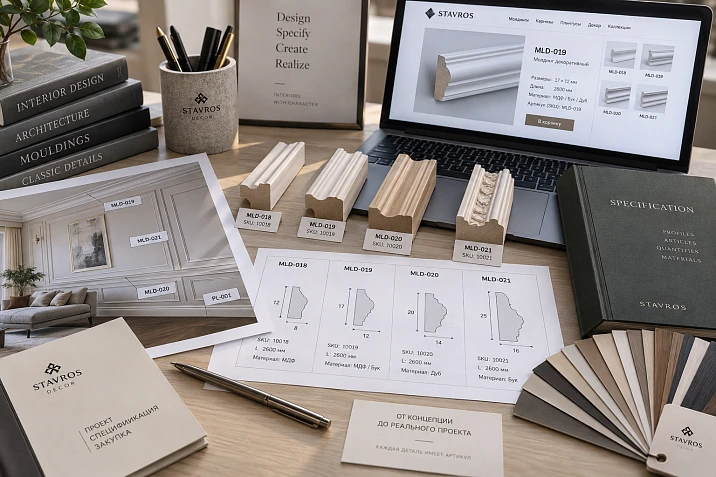
A specification with the entry “polyurethane molding — 42 m” does not define a purchase. The cross-section, commercial length, material of the specific version, and number of strips are unknown. Even a nearby photograph does not remove the ambiguity: similar profiles may have different dimensions and connect differently to the corner trim.
It is more convenient to manage moldings for a design project through short tags — for example, M-01 and M-02. Each tag receives a decoding with the actual SKU, dimensions, and finish. This link is preserved on elevations, in the model, in details, and in the order. Then Moldings made of polyurethane you can select and purchase using verifiable data, rather than guessing again from the image at every stage.
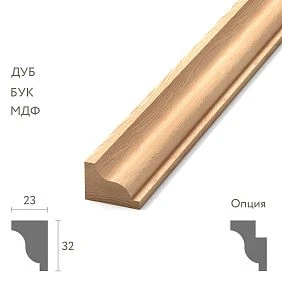
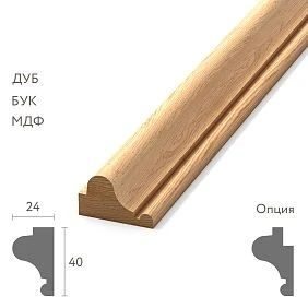
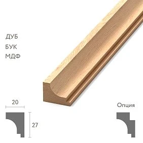
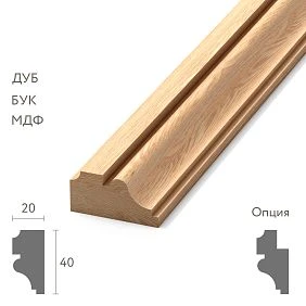
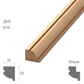
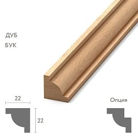
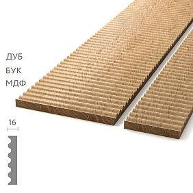
A project tag and a commercial SKU solve different tasks
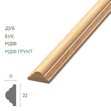
Tag M-01 designates a position within a specific project. For example, the main profile of the living room wall frames. SKU MLDPU-002 identifies the product in the STAVROS catalog. The tag links the drawings to one another, while the SKU helps find and order the product.
Therefore, the entry should contain both designations: “M-01 — STAVROS — MLDPU-002 — selected version.” If the product is replaced after approval, the function of M-01 may be preserved. At the same time, its decoding changes, and the affected images, details, and calculations undergo re-verification.
Preserving the tag does not exempt you from adjusting the geometry. It only allows you not to rename one project position in all documents with each approved replacement.
The SKU also should not be shortened to the last digits. The designation “002” may appear for different types of products and manufacturers. The register retains the full factory name of the code, including significant suffixes and an indication of left- or right-hand version. Project abbreviations are used separately from it.




It is better to establish designation rules before issuing drawings
For a small project, sequential codes M-01, M-02, M-03 are sufficient. Their meaning is explained by the general table. It is not necessary to encode the room, material, color, and size in the code itself: a long designation is harder to read and maintain when changes are made.
The proposed system is an internal project rule. The explanatory note to the set describes how it is structured. For example, "M" is used for moldings, "P" for baseboards, and "K" for cornices. These designations must not conflict with the already accepted marking of other sections.
Choose one alphabet. The Latin M and the Cyrillic М look similar, but for search and automatic summaries they are different characters. In the examples in this article, project codes are written with the Cyrillic letter М.
Excluded items are not renumbered just for a neat sequence. If M-02 is no longer used, it is marked as excluded, preserving the history. A freed-up code is not reassigned to another profile in the same project: otherwise old sheets will begin referring to a new product.
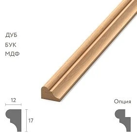
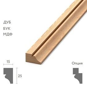
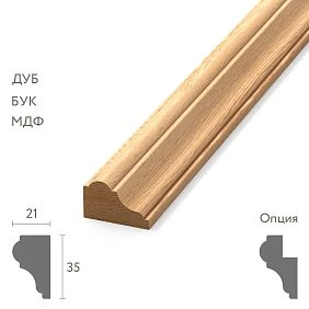
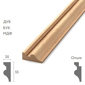
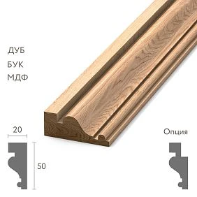
Our factory also produces:
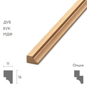
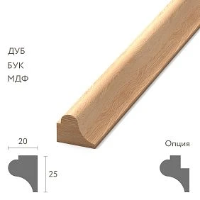
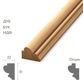
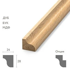
The general register becomes the source for decoding codes
The molding register is a single table mapping project designations to products. Captions, specification data, and information for the request are obtained from it. The person responsible for keeping the table up to date is determined in advance.
Below is a conditional example. Product characteristics are taken from STAVROS cards, while purpose and statuses are shown to explain the methodology.
| Code | STAVROS product | Dimensions, mm | Material | Function in the example | Status |
|---|---|---|---|---|---|
| M-01 | MLDPU-002 | 22 × 11 × 2600 | Polyurethane | Main wall frames | Approved |
| M-02 | MLDPU-001 | 10 × 6 × 2600 | Polyurethane | Inner thin contour | Approved |
| M-03 | MLDPU-027, version 20 × 12 | 20 × 12 × 2600 | Polyurethane | Additional embossed line | Candidate |
| M-04 | MLDPU-002 | 22 × 11 × 2600 | Polyurethane | Horizontal lines on panels | Approved |
The working register includes the finish, file links, the date of specification verification, related sheets, and the revision. The quantity can be tracked in a separate schedule linked via the item code. This way, the identification table is not overloaded with a list of all segments.
If data is copied between documents manually, a mandatory reconciliation point is set. A shared table is only useful when the drawings actually correspond to its current version.
Get Consultation
One SKU can include several size versions
The MLDPU-027 product page lists two options: 14 × 9 × 2600 and 20 × 12 × 2600 mm. Therefore, the line "STAVROS, MLDPU-027" is not enough to uniquely identify the order. The selected dimensions must accompany the item code in the register and the request.
For moldings, check width A, thickness C, and commercial length L according to the specific product page. If the product uses other dimension designations, read them from its drawing. Dimension C cannot automatically be considered the depth of each recess in the profile: it characterizes the corresponding overall dimension of the product.
STAVROS catalog filters by width, thickness, product type, and collection help narrow down the selection. After filtering, still open the product page: matching two dimensions does not confirm the same cross-section or material.
Reliable identification consists of the manufacturer, the full item code, and the selected variant. Depending on the product, the variant may include size, material, and factory finish. If the product page and the drawing disagree, clarify the issue before approving the item and keep the confirmation received.
When profiles need separate marks
Different cross-sections, materials, and ornament variants must be distinguished in the documentation, even if they look almost identical from a general angle. Otherwise, the M-01 callout will start to mean several products, and the assembler will have to choose between them independently.
Different functions can also be separated by marks. In the example, M-01 and M-04 are linked to the same MLDPU-002 but belong to different groups of sections. This is convenient if the groups are produced on different sheets or passed to different contractors. Such detail is needed for managing the work, not for increasing the number of designations.
Rotating a single profile during installation does not by itself create a new product. The installation direction is shown on the cross-section or in a note. If, however, the mirrored pattern requires a separate factory variant, it is recorded as its own item.
When a product is fully replaced in its former function, the mark can be retained with a new revision. If the old and new profiles continue to be used simultaneously, different marks are needed. Otherwise, it is impossible to determine unambiguously which of them relates to a specific section.
A profile mark does not replace the designation of the installation location
One M-01 may appear on several walls. This is not a reason to assign a new product code to each strip. The product type and its location are better accounted for separately.
For the list of segments, the combination "room — wall — frame — side — mark" is sufficient. For example: "Living room, wall 2, frame 3, left side, M-01". Such a description allows you to verify the length against the elevation drawing and understand where the prepared part is intended.
Separation is especially important with repeated images. One frame may be shown on the elevation drawing, the general view, and a close-up fragment. If all lines are summed without accounting for the installation location, the quantity will triple. For calculation, the primary geometry source is determined; additional images serve as clarifications.
For repeated rooms, the multiplier is recorded separately. The label "typical number" does not yet indicate how many times the set should be repeated. The schedule must show the number of identical rooms and exceptions to the typical solution — for example, a mirrored layout or a modified pier width.
Straight and flexible versions are accounted for separately
If straight and flexible versions are actually available for the project, they must not be hidden under a single line with a combined footage. They may differ in product codes, application conditions, quantity, and installation requirements.
Within the project, the designations M-01 and M-01-G may be used. The suffix "G" here is a conventional project annotation; it does not create a factory article number and does not confirm the existence of a flexible version of the selected product.
Before assigning a product to such a position, its availability, cross-section, permissible bending direction, and radius limitations are clarified. A single entry of "flexible" is not enough: the profile must suit the specific curved surface.
The straight and curved sections are shown separately and in the segment schedule. At the transition point, the geometry match, the appearance of the joint, and the finish are checked. If the flexible version has not yet been confirmed, the corresponding mark remains an open project question, even when the entire curve has already been drawn in the visualization.
Corner decor receives its own positions
Compatibility with the moulding does not make the corner overlay part of a linear metre. It is a separate item that requires a product code, dimensions, quantity, and a link to the main profile.
For example, MLDPU-002U measuring 172 × 172 × 13 mm It is intended for forming the corner of a frame with MLDPU-002. In the project, it can be assigned the mark UG-01 and linked to M-01. Its overall dimension cannot be taken as the length to be subtracted from each straight side without verification.
Use the section for selection decoration for moldings, and the junction is refined based on the geometry of the specific parts. Left and right versions are handled separately. Four mirrored pairs mean four left and four right items.
If a ready-made commercial set is purchased, it can be listed as a single procurement item while maintaining the confirmed composition. But an unspecified entry such as “M-01, set” does not replace the list of required overlays. For the installation layout, their designations and locations must still be clear.
The leader on the unfolded view must unambiguously indicate the profile
A short mark on the drawing is sufficient if there is a nearby reference to its explanation. A full product description next to each line overloads the unfolded view and increases the number of places that have to be corrected when replacing.
The leader arrow is directed to the specific profile. This is especially important for a double frame: the label M-01 placed between two lines does not explain which one is designated. The outer and inner contours receive separate leaders or a clear common marking scheme.
The dimensions are supplemented by indicating the accepted basis — along outer edges, the inner field, or axes. The mark identifies the item, but does not by itself indicate how the frame was measured.
On repeating sections, a general note with a clearly outlined scope is acceptable. The wording “all moldings M-01” is not suitable for a sheet where there are exceptions. Line color can aid reading, but the designations must remain understandable on a black-and-white printout as well.
Marking in 3D links the image to the real item
In a scene, it is convenient to give objects or groups a name that includes the project mark and the product code: for example, "M-01_STAVROS_MLDPU-002". The size variant is additionally stored in properties or a linked registry. Names like "new molding" and "latest version" do not provide this link.
After import, check the units of measurement and the actual cross-section. If a 22 × 11 mm profile is stretched to a nominal 35 × 8 mm, the MLDPU-002 label no longer matches the displayed product. For a different geometry, select a different actual product.
The length of the straight section is modeled while preserving the cross-section. For an ornamental profile, the shape and spacing of the motifs are also preserved: arbitrarily stretching the pattern changes what will be supplied.
The mark applies to all linked objects describing this item. After replacement, check hidden variants and duplicate instances: otherwise, different moldings with the same name may remain in different views of the same room.
In the DWG library, product source files and project files are kept separate
In the STAVROS section “Catalogues and drawings” drawings and 3D materials for design are provided. The resulting file is matched against the product card and the selected size, then used in the working project.
It is convenient to store the product source file by manufacturer, product code, and finish. The project copy is linked to mark M-01. These are different storage levels: in the next project, M-01 may mean a completely different profile, so a single shared file with that name is unreliable.
For each cross-section, the units of measurement, orientation, installation side, and source are preserved. If the position of the wall or base is shown schematically, this is noted. An enlarged fragment on a sheet may use a different image scale, but the product geometry in the model must remain actual.
When updating the library, do not silently replace source files inside already approved projects. First determine whether the product has changed, the file has been corrected, or a different size variant has appeared. The current set must be reproducible from the saved data.
The node number designates the assembly, and the mark designates the product
Node UZ-04 can show the junction of the molding to the casing. Inside it, M-01, the casing designation, and gap dimensions are present. The node number must not be used instead of the article number or profile grade.
A single M-01 can belong to several nodes: next to the door, on the panel, at the baseboard. Therefore, it is useful to keep a list of related parts in the registry. When replacing the molding, it is immediately clear which locations require checking.
Suppose a profile 11 mm thick is installed on a panel 6 mm thick. The nominal projection from the wall will be 17 mm, excluding the installation layer. With a casing protruding 15 mm, the entire assembly is compared, not just dimension C of the molding. The 2 mm difference applies to this conditional example.
By the same principle, M-01 is linked to baseboard P-01 and cornice K-01. Keeping the three grades helps verify the system as a whole, even if only one of its elements changes.
The finish is recorded separately from custom article number changes
A single profile can be painted differently in different rooms. For this, the factory article number is not rewritten. A finish field is added to the project, for example O-01, with a reference to the approved coating and sample.
Variants can be designated as M-01.1 and M-01.2, or combinations such as "M-01 + O-01" and "M-01 + O-02" can be used. The chosen method is described in the legend and applied consistently. When counting, the distribution of parts by finish is preserved.
If the manufacturer itself uses a separate article number or product variant for the factory coating, this designation is preserved in the procurement data. The rule of separate finish accounting does not mean that actual factory versions can be ignored.
When coordinating via Samples and catalogs it is recorded what exactly has been checked: shape, material, surface preparation, or final coating. Approval of a color on a different substrate does not automatically confirm the appearance of the painted molding. It is useful to keep the date and a signed sample of the selected system.
Statuses show the readiness level of each brand
The presence of an item code in the registry does not mean it can be ordered. A position may be suggested for comparison, selected by image, or fully approved. These states should be clearly distinguished.
| Status | What is established | What else is required |
|---|---|---|
| Candidate | A suitable product has been found | Compare and make a decision |
| Selected | A preferred option has been identified | Complete the assigned checks |
| Sample approved | The specified sample has been approved | Check the remaining conditions of use |
| Approved | Design solution composition approved | Prepare the confirmed quantity for ordering |
| Ordered | Specific composition transferred and confirmed | Monitor receipt |
| Received | Delivery accepted according to the established inspection scope | Transfer details to work |
Next to the status, indicate the date, the responsible person, and open questions. The “sample approved” mark does not replace checking the assembly if it has not yet been developed.
For a long project, it is convenient to track approval and delivery as separate fields. Then a partially received batch does not hide the fact that the profile has been approved. The quantity of received strips is recorded as a number: the word “received” without a quantity does not show whether the delivery is complete.
Sample ordering is also separated from purchasing the installation batch. One received strip for test painting does not mean that the requirement for M-01 is closed. If, after approval, it is allowed to be used in work, this is reflected in the balance and the cutting map. If the sample must be kept intact as a reference, it cannot be deducted from the quantity to be purchased.
Changing the grade is processed through the decision history
When replacing, the previous and new versions, the reason, the date, and the list of checked documents are retained. Updating only the item code in the registry is not enough if the profile has already been used in drawings.
Let us consider a hypothetical history of item M-03. It illustrates a size change within a single item code, without assumptions about availability or lead times.
| Revision | Code | Version MLDPU-027 | Basis for the entry | Condition |
|---|---|---|---|---|
| 01 | M-03 | 20 × 12 × 2600 mm | Initial selection | Candidate |
| 02 | M-03 | 14 × 9 × 2600 mm | Reduction of the relief line accepted | Approved after review |
With an outer frame width of 600 mm, replacing a 20 mm wide profile with a 14 mm one will increase the inner field from 560 to 572 mm. Both the projection and the perception of the line will change. The visualization, section, junctions, and dimensions that depended on the inner boundary are checked.
If the larger version is retained on part of the walls, M-03 cannot be rewritten for the entire project. For the second variant, a separate mark is introduced and the scope of application of each is specified. Revision numbers reflect the history, while marks are the simultaneously active items.
The reference and price supplement the entry but do not replace identification
The registry stores a direct, clean link to the product page. A link to a section or search results forces the specifier to select the item again. For a multi-variant product page, the required dimensions and material must be indicated alongside it.
It is also useful to save the verification date and the original specifications used in the project. Website content may be updated, so a single link will not explain which version was agreed upon several months ago. Before ordering, current information is compared against the project record.
The price relates to a commercial offer from a specific date. An entry like "M-01 — molding for such-and-such amount" is unreliable: the cost may change, and different items may cost the same. The SKU and finish are stored independently of the price.
If the supplier uses their own abbreviated designation on the invoice, it is matched against the full product code. A matching image or price is not sufficient confirmation. An unclear line is clarified before payment, and the interpretation is recorded in the order documents.
The specification links the brand to lengths and product units
From the registry, the manufacturer, SKU, dimensions, material, finish, and link are carried over into the specification. From the cut list — the calculated length. The number of strips is obtained from the cutting map and supplemented by a separately agreed reserve.
For example, let's take six solid segments of 2400 mm and six of 1000 mm for M-01. Total 20.4 m. With a product length of 2600 mm, the long segments will occupy six strips, and the short ones — three more, two per strip. That gives nine strips without a separate reserve. The saw cut, end trimming, and profile orientation are taken into account when preparing the cutting map.
Simply dividing 20.4 by 2.6 and rounding gives eight, so the total meterage cannot be sent to the purchaser as a ready order calculation. The lengths remain linked to the brand and installation locations.
If the segments changed after the drawing was adjusted, the calculation sheet and cutting layout are updated. The SKU itself may remain the same. Checking only product codes will not detect such an error.
Identical products are combined in the order while preserving the distribution
M-01 and M-04 from our registry belong to the same MLDPU-002 of identical design. Let's add six horizontal segments of 1000 mm each for M-04 to the previous calculation. Three more strips of 2600 mm length are provided for them.
| Project team | MLDPU-002 design | Ready-made segments | Planks |
|---|---|---|---|
| M-01 | 22 × 11 × 2600 mm | 20.4 m | 9 |
| M-04 | 22 × 11 × 2600 mm | 6 м | 3 |
| Combined requirement | Same execution | 26.4 m | 12 |
| Reserve taken for the example | Same execution | One whole strip | 1 |
| Final request | MLDPU-002, polyurethane, 22 × 11 × 2600 mm | 33.8 m in commercial strips | 13 |
The purchaser receives one trade line, while the installation schedule retains two design groups. The reserve here is assigned once for the combined requirement.
Only genuinely identical procurement executions are combined. Different materials, factory finishes, and dimensional variants remain separate lines. With joint cutting optimization, the quantity may change, but the new result is documented in a new card. Simply combining names does not justify reducing an already calculated number of strips.
Transfer to order completes the marking verification
Before buy polyurethane moldings, the path of each approved mark is checked: from the callout on the drawing to the order line. Under M-01, the product, dimensional execution, finish, associated assemblies, cut pieces, and final quantity must be found.
It is convenient to perform the check on one randomly selected part. Can its designation be used to determine which profile is needed, where it is installed, which sheet the work is performed according to, and from which trade item it is obtained? Then all exceptions are verified: flexible sections, mirrored parts, different coatings, and agreed substitutions.
Additionally, the list of marks on active sheets is compared with the register. A callout without a decoding leaves the product undefined. An approved line without application locations, on the other hand, may turn out to be a forgotten variant that does not need to be purchased. The numbers of excluded items are checked separately: after a layout change, they sometimes remain in an explanatory assembly or schedule. Such reconciliation helps remove unnecessary purchasing and detect a missing profile before submitting the request.
The request specifies the current revision of the schedule, and availability and delivery terms are clarified for the specific quantity. The STAVROS section can be used to discuss the configuration for designers and architects, by providing the register and the necessary drawing fragments.
The factory designations are retained on the received packages, and design marks or room distribution are added. This way, the link between M-01 and the actual profile continues to work on site, where the specialist needs the specific part, its location, and the current drawing.