Article Contents:
- MLD-001 10×6 mm: which item is included in the calculation
- Why a thin profile is convenient for two nested contours
- Outer contour
- Inner contour
- Clear gap
- Module
- One double frame — eight parts
- Outer contour
- Inner contour
- Why two rectangles cannot be marked independently
- Why the instruction "inset the inner frame by 30 mm" is dangerous
- How to derive the inner contour from the outer one
- Why side light is especially useful for checking a double frame
- Why the thin MLD-001 does not forgive an "almost identical" gap
- How to avoid error accumulation from field to field
- Why a laser line does not replace a double-frame template
- Outer contour
- Inner contour
- Example cutting of an external vertical 2200 mm
- Example cutting of an internal vertical 2040 mm
- How to calculate horizontals as a common pool
- Why external and internal contours should be optimized as a common pool
- How to label parts after cutting
- Why you shouldn't store everything as “MLD-001 parts” after cutting
- How to assemble the installation kit for one module
- How to kit out an entire floor or room
- Level 1 — module
- Level 2 — zone
- Why exceptions should not change the reference module
- How to maintain the same gap on panels of different widths
- Principle 1 — the gap between contours is constant
- Principle 2 — the entire module scales proportionally
- Why the same gap does not mean the same size of inner frames
- How to check the corner zone of a double frame
- The orientation of the quarter-round profile must be the same
- Why both frames must be assembled completely before duplication
- How to work with 1000 mm beech and oak
- How to work with 2400 mm solid wood
- Why 2600 mm MDF must be calculated separately
- Practical example: the same double frame in MDF and oak
- Outer contour
- Internal
- What the preliminary cutting layout for 2600 mm MDF looks like
- 2200 мм
- 2040 мм
- Horizontals
- How to use leftovers if the project has other field types
- Remnant list after the main cutting plan
- Why the total remnant in meters is of little use
- How to determine the minimum useful remnant
- How to use a rigid module template
- Why a template should store more than just the inner rectangle
- How to check the squareness of a double frame
- Why an inner contour error is visually stronger than an error of both contours combined
- How to work with a field next to a door
- How to work with a field next to a column
- Keep a fixed gap between contours
- Change the composition
- How to work with a short wall section
- How to work with a switch or outlet
- Why standard allowances and exceptions should be counted separately
- How to conduct module revisions
- What to do with old parts after revision
- Long reserve
- Short reserve
- Material for a test cut
- Repair stock
- Why short offcuts are not equal to a long reserve
- A whole plank as a universal repair resource
- How to account for natural beech and oak in a double frame
- When visual grouping of solid wood is not needed
- Why packaging should not replace kitting
- How to mark the source long stock before cutting
- What happens after cutting
- How to kit parts for a project
- Why the price per linear meter doesn't solve the supply selection problem
- How to place a reorder
- What to do if only the inner horizontal is damaged after handover
- How to store the site's repair passport
- When it's still too early to buy MLD-001 in bulk
- Design level
- Production level
- Procurement level
- Final readiness matrix
- How to verify the purchase figure using the reverse method
- Why such a reverse balance is especially useful for large series
- How to use the first queue to refine the second
- Why overspending should be classified by cause
- What counts as a successful serial module
- How to work when installation is carried out by two crews simultaneously
- How to accept a finished double frame on site
- Why an acceptance template is more useful than subjective evaluation
- 1. Multiply the outer perimeter by two
- 2. Mark two contours independently
- 3. Fail to determine which line the gap is measured from
- 4. Carry over the module from the previous field
- 5. Fail to assemble a full-scale reference
- 6. Count only meters
- 7. Fail to separate the outer and inner contours after cutting
- 8. Cut long stock into short parts first
- 9. Mix MDF, beech, and oak
- 10. Treat short offcuts as a full-fledged reserve
- 11. Give the installers all of MLD-001 in one batch
- 12. Do not encode the revision
- 13. Reorder the "same molding"
- 14. Do not store the reference sample and control paint-out
- 15. Change the inner contour locally due to an outlet without creating a new type
- What size is MLD-001?
- What lengths are available for the solid wood?
- What is the length of MDF?
- Can MLD-001 be used for a double frame?
- What gap should be left between the contours?
- Should the gap be measured from the edge or from the axis?
- Do I need to make a template?
- How many parts are in one rectangular double frame?
- Why can't you just double the perimeter?
- Can leftover outer frame pieces be used for the inner frame?
- Can MDF and solid wood be mixed?
- How do you calculate the reserve?
- How many items fit in a packing frame?
- Where can I check current availability?
- What should be sent to the supplier?
- What a supplier request should look like

A double frame looks simple only as long as we are talking about a single wall field. On a project with 30–40 repeating modules, a small marking error begins to accumulate: the outer contour stands level, the inner one on one field is shifted a few millimeters upward, on the next — to the right, and after a few more modules the clean gap between the two lines visually "drifts." The profile itself may be cut and installed perfectly.
Therefore, molding MLD-001 should not be bought wholesale for a series of double wall frames using the formula "perimeter of the outer frame × 2." The outer and inner contours are two different sets of parts, linked by one coordinate system and one approved clean gap.
Work sequence:
reference field → outer contour → gap measurement base → inner contour → eight finished parts → standard module → cutting map → number of commercial strips → marking of outer/inner parts → reserve → wholesale order.
The main principle of the article:
the inner frame cannot be marked out anew as an independent rectangle — it must be derived from the approved outer contour or from the common coordinate model.
This is exactly what preserves the same visual interval across the entire series.
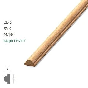
MLD-001 10×6 mm: which product is involved in the calculation
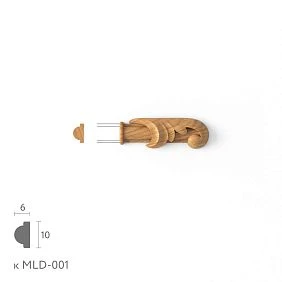
The current STAVROS product page shows the standard wooden MLD-001 in several versions:
| Material | Section | Product length |
|---|---|---|
| Beech | 10×6 mm | 1000 мм |
| Oak | 10×6 mm | 1000 мм |
| Beech | 10×6 mm | 2400 мм |
| Oak | 10×6 mm | 2400 мм |
| MDF | 10×6 mm | 2600 мм |
For the current versions, the sanding quality "Prestige" is specified. The product page also provides for a rigid packaging frame.
Product page: buy a wooden molding MLD-001.
This article focuses specifically on the standard MLD-001, not the primed MLD-001-MG.




Why a slim profile is convenient for two nested outlines
A 10×6 mm cross-section allows you to create a light, graphic pattern where two lines don't turn the wall into a heavy architectural frame.
But a slim profile places higher demands on:
-
parallelism;
-
uniformity of the gap;
-
alignment of axes;
-
accuracy of angles;
-
repeatability of modules.
An error of a few millimeters on wide trim sometimes goes unnoticed.
On a thin double line, it is more noticeable because the eye compares two adjacent outlines at the same time.
Our factory also produces:



What exactly is called a double frame
So that the designer, estimator, cutter, and installer speak the same language, it is useful to establish four terms.
Get Consultation
Outer contour
The larger rectangle made of MLD-001.
Inner contour
The smaller rectangle located inside the outer one.
Clean gap
The visible strip of wall between two installed moldings.
Module
A fully approved double frame of one standard size.
For example:
M-01 — standard wall panel.
After this, it can be considered not as "two rectangles," but as a single production module made of eight parts.
Why a double frame cannot be counted as "perimeter × 2"
Let's imagine the outer frame:
1200×2200 mm.
Its net perimeter:
1200×2 + 2200×2 = 6800 mm.
If simply doubled:
6800×2 = 13,600 mm.
But the inner contour is smaller.
Let's assume that after the project was approved, it turned out to be:
1040×2040 mm.
Its perimeter:
1040×2 + 2040×2 = 6160 mm.
Total net length of the module:
6800 + 6160 = 12,960 mm.
Not 13,600.
The difference:
640 mm per field.
For 40 fields:
25,600 mm = 25.6 m.
This example shows: the formula "outer perimeter × 2" can noticeably overestimate the net calculation even before cutting.
But even the correct sum of the two perimeters still does not show how many product strips will be needed. This requires the individual lengths of the eight parts.
One double frame — eight parts
For a rectangular module:
Get Consultation
Outer contour
-
2 verticals;
-
2 horizontals.
Inner contour
-
2 verticals;
-
2 horizontals.
Total:
8 finished parts.
For 40 identical fields:
40 × 8 = 320 parts.
It is this quantity that becomes the basis of the production sheet.
The total linear footage remains a control value, but is no longer the primary planning unit.
Why two rectangles cannot be marked out independently
Bad scheme:
-
the outer contour is marked out from the floor and wall;
-
the inner one is again marked out from the floor, ceiling, and side wall;
-
the procedure is repeated anew on the next field.
Each set of measurements carries its own error.
Result:
-
the gap at the top is one;
-
at the bottom it is another;
-
the vertical fields differ;
-
the centers of the frames shift;
-
the series loses its rhythm.
Stronger:
first the outer contour is established;
the inner one is built from it or from the same common coordinate model.
In this case, the two frames are connected by a single system.
From which line should the gap between two MLD-001 be measured?
Phrase:
leave 30 mm between the frames
insufficient.
It is necessary to determine exactly what these 30 mm are between.
Different reference bases are possible:
-
between the nearest visible edges of the profiles;
-
between the installation axes;
-
between the template control lines;
-
between the overall dimensions of the finished frame units.
For the article, the clearest logic is that of a clean visible gap between the nearest edges of the installed moldings.
But a specific project may use a different method.
The main point:
one method is chosen once and applied to all modules.
Why the instruction “set the inner frame back by 30 mm” is dangerous
The technician may understand:
30 mm from the outer edge of the first profile to the outer edge of the second.
Installer:
30 mm between the axes.
Designer:
30 mm of clear space between the visible faces.
Three people receive three different inner contours.
Therefore, the working documentation must clearly show:
the clear gap is measured between the nearest front edges of MLD-001.
Or another approved option.
Do not leave the meaning open to interpretation.
How to derive the inner contour from the outer one
For example:
-
outer frame dimension — 1200×2200 mm;
-
the MLD-001 profile has a face width of 10 mm;
-
the clear gap between profiles — conventionally 30 mm.
If the dimensions of the outer and inner contours are specified along the outer edge of the molding, the inner frame cannot simply be reduced by 60 mm.
Need to consider:
-
the width of the outer profile;
-
the clear gap;
-
the width of the inner profile;
-
the selected measurement base.
That is why it is better to record the finished dimensions of both frames directly on the working drawing, rather than making the installer reconstruct the formula every time.
The article does not set a universal gap.
It shows how not to lose the one already approved.
First, one reference field is assembled at full scale
Before a full wholesale purchase, it is useful to assemble one M-01 module.
Checked:
-
external size;
-
inner size;
-
the clear gap;
-
four outer corners;
-
four internal;
-
distance to the floor;
-
distance to ceiling;
-
connection with doors and furniture;
-
Side light.
A reference sample is not needed for a decorative experiment.
Its purpose is to turn a design solution into repeatable production geometry.
Why side light is especially useful for checking the double frame
MLD-001 has a small offset of 6 mm.
Under side lighting, two parallel lines produce thin shadows.
If the gap differs by a few millimeters, this may be more noticeable specifically in grazing light.
Therefore, it is better to inspect the reference sample:
-
frontally;
-
at an angle;
-
with a side light source.
This helps validate the geometry before replication.
How to validate a single double-frame template
After the reference is established, the following are fixed:
-
external size;
-
inner size;
-
the clear gap;
-
measurement base;
-
lengths of outer verticals;
-
lengths of outer horizontals;
-
lengths of inner verticals;
-
lengths of inner horizontals;
-
profile orientation;
-
position relative to the wall.
It turns out:
M-01 / revision 1.
Now 40 identical fields are not re-marked out as 40 separate design tasks.
They repeat one approved module.
Why the thin MLD-001 does not forgive an "almost identical" gap
On a wide frame, the viewer may first perceive the profile itself.
On MLD-001 the line is delicate, so the following are more noticeable:
-
rhythm;
-
symmetry;
-
repetition;
-
the distance between the lines.
If one field has a gap of 30 mm, another 34, and a third 27, the series quickly loses its precision.
That is, a thin profile requires not less, but greater discipline in marking out.
How to avoid error accumulation from field to field
Bad method:
field 1 is marked → field 2 is taken from field 1 → field 3 from field 2.
If the first field is offset by 2 mm, the error can carry over further.
It is better to use:
-
a single laser room datum;
-
one axis;
-
reference marks;
-
an approved template;
-
dimensions from the project.
Each field is tied to a common system, not to the previous module.
Why a laser line does not replace a double-frame template
The laser maintains the overall horizontals and verticals well.
But it does not store:
-
the external size of the module;
-
inner size;
-
the clear gap;
-
the exact position of the second contour.
The template or work map defines the internal geometry.
The laser — the common base.
These are two different tools.
How to turn the M-01 reference into two parts lists
After approving the module, it is convenient to divide the parts by purpose.
Get Consultation
Outer contour
| Code | Detail | Finished length | Quantity per module |
|---|---|---|---|
| EX-V | external vertical | According to the drawing | 2 |
| EX-H | external horizontal | According to the drawing | 2 |
Inner contour
| Code | Detail | Finished length | Quantity per module |
|---|---|---|---|
| IN-V | internal vertical | According to the drawing | 2 |
| IN-H | internal horizontal | According to the drawing | 2 |
If M-01 is repeated 40 times, each quantity is multiplied by 40.
For example:
-
EX-V — 80 pcs.;
-
VN-G — 80;
-
VT-V — 80;
-
VT-G — 80.
Now the cutting works not with two perimeters, but with four serial lengths.
Why for wholesale calculation the number of parts is more important than the total linear meters
Let's imagine:
-
VN-V = 2200 mm;
-
VN-G = 1200 mm;
-
VT-V = 2040 mm;
-
VT-G = 1040 mm.
Per module:
2×2200 + 2×1200 + 2×2040 + 2×1040 = 12,960 mm.
For 40:
12,960 × 40 = 518,400 mm = 518.4 m of net parts.
If using 2600 mm MDF, simple division:
518,4 / 2,6 ≈ 199,4.
One might mistakenly conclude:
approximately 200 strips.
But this is only the lower arithmetic bound.
The real question:
how exactly are 320 parts laid out into 2600 mm blanks?
Example cutting layout for the 2200 mm outer vertical
From MDF 2600:
2600 − 2200 = 400 mm.
If the shortest part of the module is 1040 mm, the remaining 400 mm does not help the main frame.
This means that each external vertical almost certainly requires a separate strip.
For 80 external verticals:
80 strips of 2600 mm up to the reserve.
Example of cutting an internal vertical 2040 mm
From MDF 2600:
2600 − 2040 = 560 mm.
The remainder also does not cover the 1040/1200 mm horizontals.
For 80 internal verticals:
another 80 strips.
Already:
160 MDF strips.
160 horizontal pieces of two standard sizes remain.
How to count horizontal pieces as a common pool
Outer horizontal piece 1200 mm.
Inner — 1040 mm.
Checking the combination:
1200 + 1040 = 2240 mm.
remains:
360 mm.
This is a convenient pairing.
One module requires:
-
2 external horizontals;
-
2 internal.
This means two 2600 mm strips can potentially cover all four horizontals of one module:
1200 + 1040;
1200 + 1040.
For 40 modules:
80 strips.
Preliminary total:
160 + 80 = 240 MDF strips of 2600 mm.
This is significantly more than simply dividing the net linear meters by 2600.
This is exactly why linear meters without a cutting plan underestimate procurement requirements.
Why the external and internal contours need to be optimized as a shared pool
During installation, the contours must be separated.
During cutting, on the contrary, it is useful to consider their short parts together.
If one strip of 2600 mm perfectly yields:
1200 + 1040 = 2240 mm,
there is no point in prohibiting such a combination just because the parts belong to different contours.
Rule:
we optimize cutting using a common pool of one material and finish;
after cutting, we return each part to its contour using marking.
How to mark parts after cutting
The original strip is called MLD-001.
After cutting, the name alone is no longer sufficient.
For example:
M01 / EN / V / 001
Decoding:
-
M01 — module type;
-
EN — external contour;
-
V — vertical;
-
001 — picking group number.
For the internal horizontal:
M01 / IN / H / 001
If all 40 fields are absolutely identical and the parts are interchangeable, serial picking can be done without a number for each field.
If the actual fitting is individual, a number is added.
Why can't everything be stored as "MLD-001 parts" after cutting
The finished parts warehouse contains four lengths.
Visually, they look similar.
If mixed:
-
VN-V;
-
VN-G;
-
VT-V;
-
VT-G,
the installer has to sort them again using a tape measure.
This is an extra operation and an additional chance for error.
Assembly must be completed before handover to the site.
How to assemble the mounting kit for one module
For example:
M-01 / kit 07
Inside:
-
VN-V — 2 pcs.;
-
VN-G — 2;
-
VT-V — 2;
-
VT-G — 2.
Total:
8 parts.
If the corners are assembled on site, the kit remains flat.
If some of the components are pre-assembled in the workshop, the packaging is adapted.
The main thing is that the installer receives a completed module, not a general stack of parts.
How to assemble a whole floor or room
For a large project, you can work with two levels.
Level 1 — module
M-01 / 8 parts.
Level 2 — zone
For example:
floor 2 / corridor / M-01 × 12.
Then the warehouse ships 12 ready-made kits.
This is much more reliable:
floor 2 — 155 meters MLD-001.
What to do if some wall panels differ
On a real site, it is rare for all 40 panels to be completely identical.
For example:
-
32 standard;
-
4 next to the door;
-
2 by the column;
-
2 near the built-in wardrobe.
Create more:
M-01 × 32.
M-02 × 4.
M-03 × 2.
M-04 × 2.
Do not stretch M-01 "to fit" each wall.
Why exceptions should not change the reference module
If M-01 is already approved, a local column on one field does not mean that all 40 frames need to be changed.
The exception gets its own version.
This protects seriality.
One non-standard wall section should not destroy the map of standard fields.
How to maintain the same spacing on fields of different widths
There are two different design principles.
Principle 1 — the gap between contours is constant
For example:
everywhere 30 mm of clear space.
Then the inner contour changes together with the outer one, but the distance between them remains the same.
Principle 2 — the entire module scales proportionally
Then the gap can also change.
This is already a different visual system.
These principles must not be mixed randomly.
For a series, first choose one and formalize it in the drawing.
Why an equal gap does not mean equal sizes of the inner frames
The fields can be:
-
1200×2200;
-
1000×2200;
-
900×1800.
With the same gap, the inner contours are different.
Therefore, it is impossible to have one universal inner frame for all types.
Each field type gets its own specification, but the same methodology.
How to check the corner zone of a double frame
Four visual lines meet at the corner at once:
-
outer vertical molding;
-
outer horizontal;
-
inner vertical;
-
inner horizontal.
If the clear gap on straight sections is the same, but at the corner the line "collapses" or widens, the viewer notices it.
Therefore, the reference sample must check not only the midpoints of the sides, but also the four corner zones.
The orientation of the quarter-round profile must be the same
MLD-001 has a small quarter-round cross-section.
If one part is flipped to the other side, the shadow and profile will change.
For a double frame, the error is especially noticeable: two adjacent contours begin to reflect light differently.
Therefore, the profile orientation is fixed before mass cutting and installation.
There is no need to create a complex theory.
A control photo/diagram is sufficient:
the front side and the direction of the convexity.
Why both frames need to be fully assembled before replication
Arithmetically, the interval can be correct.
In person, it will become clear:
-
the lines are too close;
-
the shadows visually merge;
-
the inner margin is too tight;
-
the corners look heavy;
-
the double line clashes with the door or furniture.
After purchasing several hundred planks, changing the decision is more expensive.
Therefore, a full-fledged reference sample is part of preparing a wholesale order.
How to work with beech and oak 1000 mm long
The array has a short version of 1000 mm.
For this article, it is not the central intent.
The principle is as follows:
-
a general map of parts is built;
-
long verticals are protected;
-
2400 mm remnants are distributed;
-
shortfall is checked against 1000 mm.
For example, internal horizontals of 820 mm may be candidates for 1000 mm.
But if they are perfectly covered by 2400 remnants, a separate short purchase may be unnecessary.
How to work with a 2400 mm array
Long parts are reserved first.
For example:
-
VN-V 2200 mm;
-
VT-V 2040 mm.
Both require a solid long-length piece.
After them, the following remain:
-
200 mm;
-
360 mm.
If the short horizontal is larger, these leftovers do not cover the main module.
Consequently, the solid wood layout can differ very noticeably from MDF 2600.
Why MDF 2600 mm must be calculated separately
MDF provides an additional 200 mm compared to solid wood 2400.
Sometimes this allows combining two parts.
For example:
1500 + 1000 = 2500 mm.
It fits in 2600.
It does not fit in 2400.
Therefore, you cannot calculate MDF and then replace the material with oak without recalculating.
Practical example: the same double frame in MDF and oak
Let's assume the parts:
-
2×2200;
-
2×1200;
-
2×2040;
-
2×1040.
For MDF, we have already seen a convenient combination:
1200 + 1040 = 2240 mm.
For oak 2400, it also fits.
But the long verticals leave remnants:
2200:
2400 − 2200 = 200 mm.
2040:
2400 − 2040 = 360 mm.
That is, there is less free stock.
If short fillers of 500–550 mm appear in the project, MDF can use leftovers better than solid wood.
This needs to be seen on the map before ordering.
Practical scenario: 40 standard double frames M-01
Let's take a conditional object:
-
40 identical wall fields;
-
outer contour 1200×2200 mm;
-
inner contour 1040×2040 mm;
-
one MLD-001;
-
one finish;
-
one approved clean interval.
Per module:
Get Consultation
Outer contour
-
2 verticals of 2200 mm;
-
2 horizontals of 1200 mm.
Internal
-
2 verticals of 2040 mm;
-
2 horizontals of 1040 mm.
Total:
8 parts.
For 40 modules:
-
80×2200;
-
80×1200;
-
80×2040;
-
80×1040.
Now you can build a map for a specific product length.
What the preliminary cutting of 2600 mm MDF looks like
Long parts are protected first.
2200 мм
80 parts.
Each occupies one strip:
80 strips.
Remainder of 400 mm.
2040 мм
80 parts.
Also:
80 strips.
Remainder of 560 mm.
Horizontals
1200+1040:
2240 mm.
360 mm remains.
For 160 horizontal pieces, paired together:
80 strips.
Total:
240 MDF strips 2600 mm to a separate reserve.
Purchased length:
240×2600 = 624,000 mm = 624 m.
Net length of parts:
518.4 m.
The difference:
105.6 m.
This does not mean that 105.6 m should be considered “useless waste.”
This difference includes:
-
80 remainders of 400 mm;
-
80 by 560 mm;
-
80 by 360 mm;
-
technological waste;
-
potential stock for other short parts of the object.
That is why, after the main cutting, the leftovers should not be thrown away but classified.
How to use leftovers if the object has other types of fields
Suppose, besides M-01, there are 12 narrow modules M-02.
They contain a short part of 520 mm.
Then the 560 mm leftover after the internal vertical of M-01 becomes useful.
From 12 such leftovers, 12 parts of M-02 can be obtained.
This reduces the need for new strips.
If M-01 and M-02 are counted independently, this saving is lost.
Therefore, the final cutting plan is optimized across the entire batch of a single material and finish, not just within one frame type.
Remainder list after the main cutting plan
Example:
| Code | Length | Material | Finish | Possible purpose |
|---|---|---|---|---|
| O-001 | 560 мм | MDF | E-01 | M-02, short part |
| O-002 | 400 мм | MDF | E-01 | test assembly |
| O-003 | 360 мм | MDF | E-01 | small elements |
| О-004 | 1180 мм | Oak | T-01 | Repair reserve |
After assignment:
О-001 → М-02 / ВТ-Г.
It is no longer free.
Why the total remaining length in meters is of little use
The warehouse may contain:
remaining MLD-001 — 27 m.
But if these are:
-
50 pieces of 400 mm;
-
10 of 560;
-
2 of 700;
they do not replace a long vertical of 2040 mm.
Therefore, not only the total is stored, but also the length structure.
How to determine the minimum useful offcut
No universal rule is needed:
keep everything longer than 300 mm.
If the shortest part of the project is 520 mm, the remaining 400 mm is not used in the main series.
If there are test or repair elements of 350 mm, it is already useful.
The minimum useful length is determined by the actual parts list of the object.
How to mark out 40 fields without accumulating error
A strong scheme:
-
establish a common base horizontal line with a laser;
-
fix the common level of the outer frames;
-
transfer the position of each M-01 using the control dimensions;
-
inside each module, build the inner contour using a template or fixed dimensions;
-
check the diagonals and the gap;
-
only then install the molding.
Do not:
finish the first field and use a tape measure to build the next one from it.
This way, an error in the first field does not become the basis for the second.
How to use a rigid module template
The template can define:
-
outer dimension;
-
internal;
-
position of the axes;
-
control gap.
This does not have to be a complex structure.
Even a simple marking system with fixed control points reduces the risk of differences between installers.
It is especially useful if the project is carried out by several crews.
Why the template should store more than just the inner rectangle
If it only shows the dimensions of the inner frame, the question remains:
where is it located relative to the outer one?
Therefore, the template must be linked to the common base.
For example:
-
left outer corner;
-
top outer edge;
-
inner control points.
This way the gap is reproduced automatically.
How to check the squareness of a double frame
Even if the verticals and horizontals are set by laser, the rectangle must be checked as a system.
For the control module, it is useful to verify:
-
diagonals of the outer contour;
-
diagonals of the inner contour;
-
parallelism;
-
equal gap on all four sides.
The article does not specify a construction tolerance in millimeters.
The tolerance is determined by the project and the quality of installation.
The key is to check using the same method across the entire series.
Why an error in the inner contour is visually more noticeable than an error in both contours combined
If the entire module is shifted by a few millimeters relative to the wall, it is sometimes almost unnoticeable.
If the inner contour is shifted relative to the outer one, the gap becomes:
-
28 mm on the left;
-
34 on the right;
-
top 30;
-
bottom 32.
The eye immediately detects a violation of nesting.
Therefore, the internal geometry of the module requires separate control.
How to work with the space next to the door
A standard M-01 may not fit due to the door casing or doorway.
There is no need to compress one side gap and leave the module under the old code.
Create more:
M-02 — space by the door.
It records:
-
new external dimension;
-
new internal;
-
the same principle of a clear gap;
-
own lengths of the parts.
This way, the exception becomes repeatable if similar places occur again.
How to work with the field at a column
A column can reduce the width of the available wall.
There are two scenarios:
Keep a fixed gap between the contours
Then the entire module becomes narrower.
Change the composition
If the inner field becomes too narrow.
The decision is made by the project.
Purchasing receives the already finished type M-03.
How to work with a short wall section
If a double frame becomes too cramped, there is no need to preserve two outlines at any cost.
Possibly, on a short wall section:
-
only one outline;
-
a different frame type;
-
omitting MLD-001.
The expert specification should allow for the option:
M-04 without a double frame.
This is better than formally applying a single technique in an unsuitable place.
How to work with a switch or socket
If an engineering element falls into the gap between frames, you cannot simply shift the inner contour "in place" and keep the same code M-01.
Otherwise, the gap will differ on one field.
You need to:
-
change the module type;
-
or change the engineering solution;
-
or approve a local composition.
After that, the details are updated.
Why standard fields and exceptions should be counted separately
Let the object contain:
-
32 M-01;
-
4 M-02;
-
2 M-03;
-
2 M-04.
Total order:
40 double frames
too rough.
More correctly:
M-01 ×32;
M-02 ×4;
M-03 ×2;
M-04 ×2.
Each type has its own bill of materials, but a common cutting plan can combine compatible parts.
How to conduct module revisions
For example:
M-01.R1
— the first approved version.
After changing the clear gap:
M-01.R2.
If some R1 parts have already been cut, they must not quietly end up in R2.
On the marking:
M01-R2 / VT-G.
The old batch gets a separate status.
What to do with old parts after revision
Do not write off automatically.
Check:
-
whether it fits another type;
-
whether they can be shortened;
-
can it be left in reserve R1;
-
whether the finish matches.
If the part is reassigned:
VT-G R1 → M-02 G.
This is recorded in the statement.
How to create a reserve for double frames
Not:
+10 % MLD-001.
Separate risks more strongly.
Long reserve
Whole strips for verticals.
Short reserve
Horizontals and internal parts.
Material for a test cut
separately.
Repair stock
Remains after delivery.
This way, every stock item has a purpose.
Why short offcuts are not equal to a long reserve
Five meters of offcut can be ten pieces of 500 mm.
For a 2200 mm VN-V, they are useless.
Therefore, the reserve must preserve the ability to reproduce the most critical part, not just the total linear meters.
A whole plank as a universal repair resource
For 2400 solid wood or 2600 MDF, a whole plank can become:
-
a vertical;
-
into two short horizontal lines;
-
into several exception elements.
Therefore, it is reasonable to store part of the repair as whole products.
The exact quantity depends on the object.
How to account for natural beech and oak in a double frame
If the wood remains visible, two close lines of the same material are located next to each other.
A strong tonal contrast between the outer and inner contour may be noticeable.
Therefore, with a transparent or semi-transparent finish, it is useful to evaluate the parts of a single module as a visual group.
Do not promise an absolute match.
Natural wood is variable.
The goal is to avoid accidental sharp contrast.
When visual grouping of the array is not needed
If the profile is coated with opaque enamel, the natural grain is not the main factor.
Then the priority is:
-
geometry;
-
surface quality;
-
length;
-
marking.
There is no need to complicate production with invisible sorting.
How to organize acceptance of a wholesale batch of MLD-001
Before cutting, the following are checked:
-
item code MLD-001;
-
cross-section 10×6 mm;
-
material;
-
product length;
-
number of whole items;
-
surface condition;
-
compliance of packaging groups with the order.
If ordered:
beech 1000 — 30 pcs.;
beech 2400 — 120 pcs.;
MDF 2600 — 80 pcs.,
acceptance:
total 230 MLD-001
insufficient.
Each line must match separately.
Why packaging should not replace kitting
The MLD-001 card provides for a rigid transport frame. The current card specifies norms of up to 60 solid wood items and up to 150 MDF items in one frame.
This norm applies to the transportation of the original goods.
It does not mean:
one frame = one tier;
Or:
one frame = one frame type.
After acceptance, the production batch can be redistributed by:
-
rooms;
-
module types;
-
queues;
-
reserve.
Physical packaging and assembly kits are different tasks.
How to mark the source long-length material before cutting
For example:
MLD-001 / oak / 2400 / T-01 / MAIN.
For reserve:
MLD-001 / oak / 2400 / T-01 / RESERVE.
For a short batch:
MLD-001 / beech / 1000 / B-01 / MAIN
This way the reserve does not disappear into current production, and the short and long stock are not mixed.
What happens after cutting
The original product labeling is replaced with production labeling.
For example:
M01-R1 / VN-V / set 12.
Or:
M02-R1 / VT-G / set 03.
But the picking list still retains:
-
SKU;
-
material;
-
finish;
-
revision.
This is especially useful for future repairs.
How to kit parts for the site
Bad option:
send 90 pieces of MLD-001 to floor 3.
If one supplier is sent only 520 meters, and another is sent an exact cutting plan, the offers will not be comparable.
Why the price per linear meter does not solve the supply selection problem
One option may be cheaper per meter, but:
has a different commercial length;
requires more full planks;
produces inconvenient leftovers;
creates more packaging units.
Therefore, the finished procurement configuration is compared, not a single meter.
for building materials at wholesale prices this is especially important: price becomes meaningful only after the technical requirement is finalized.
How to place an additional order
Bad request:
20 more MLD-001 needed.
Stronger:
MLD-001 / oak / 10×6×2400 / T-01 / 20 pcs. / repair of double frames M-01.
If a short flow is needed:
MLD-001 / beech / 10×6×1000 / B-01 / 12 pcs. / internal horizontals M-02.
This way, the new material can be matched with the original batch.
What to do if only the internal horizontal is damaged after handover
First, the repair remainder is checked.
For example:
oak / T-01 / 1180 mm.
If the internal horizontal is 1040 mm, the remainder may fit.
Then the whole 2400 strip does not need to be opened.
If there is no suitable stock available, a reorder is generated based on the required function.
How to store the repair passport of the property
It is useful to save:
MLD-001;
material;
product length;
finishing;
types M-01...M-04;
lengths VN-V/VN-G/VT-V/VT-G;
the clear gap;
measurement base;
remnants;
reserve.
In a few years, you won't have to restore the geometry again from a finished wall.
When it's still too early to buy MLD-001 in bulk
The main batch should not be fixed if:
the double frame exists only in the render;
the clear gap has not been approved;
the measurement base is unclear;
the internal contour is marked independently;
there is no M-01 reference standard;
standard fields are not separated from exceptions;
the quantity is calculated only in linear meters;
the material is still changing;
no cutting map;
external and internal parts do not have codes.
In this state, a preliminary budget can be calculated.
But production procurement is not ready yet.
How to check series readiness before full procurement
Before paying for the main batch, it is useful to go through three levels of verification.
Project level
The following must be approved:
outer contour;
inner contour;
the clear gap;
measurement base;
position of the module on the wall;
exception types.
If at least one of these parameters is still changing, the parts map is preliminary.
Production level
The following must exist:
reference sample M-01;
lengths of four external and four internal parts;
cutting map;
VN/VT codes;
revision;
template or installation control diagram.
It is this level that turns the design into a repeatable series.
Procurement level
Need to know:
material;
product length;
number of whole slats;
reserve;
delivery queue.
If the project only knows the net 518.4 m but does not know the number of planks, the purchase is not yet complete.
Final readiness matrix
Check Status M-01 assembled at full scale Yes/No Clearance approved Yes/No Measurement basis signed off Yes/No External parts calculated Yes/No Internal parts calculated Yes/No Exceptions marked as separate types Yes/No Material selected Yes/No Map 1000/2400/2600 ready Yes/No Long verticals reserved Yes/No Usable offcuts allocated Yes/No VN/VT codes verified Yes/No The first assembly series passed without manual correction Yes/No Reserve allocated separately Yes/No A reorder can be placed as a full line Yes/No If several key lines remain "no", it is better not to finalize a large order.
How to verify the purchase figure using the reverse method
Suppose the map gave:
240 MDF slats at 2600 mm.
Purchased length:
624 m.
Net total of parts:
518.4 m.
The difference:
105.6 m.
Now it needs to be explained by the structure of the remaining stock.
In our conditional example, the following appear:
80×400 mm = 32 m;
80×560 mm = 44.8 m;
80×360 mm = 28.8 m.
Sum:
32 + 44.8 + 28.8 = 105.6 m.
the balance reconciles.
This is a strong check: if the purchased length is noticeably higher than the net length, and the bill of materials does not explain the difference, the cutting plan requires revision.
Why such a reverse balance is especially useful for large series
On a single field, an error in one strip goes unnoticed.
Across 40 fields, a systematic error turns into dozens of extra items.
The reverse check links:
number of planks;
net requirement;
remainders.
And it helps distinguish actual technological consumption from an accidentally inflated reserve.
How to use the first priority to clarify the second
If the object is installed by floors or zones, the first priority can be made a control one.
For example:
10 modules M-01;
2 M-02;
one spare kit.
After installation, the following are recorded:
actual consumption;
how many leftovers were actually used;
how many parts had to be redone;
whether the template was used;
whether VN and VT were mixed up.
The next queue is adjusted based on actual results.
This is more useful than automatically repeating the original map if production has already shown different data.
Why overspending should be classified by cause
Entry:
overspending of 4 strips
not very useful.
Need to know:
cutting error;
damage;
incorrect marking;
confusion of VN/VT;
module change;
defect of the original workpiece.
If the cause is marking, increasing the reserve does not solve the problem.
If the cause is a too dense layout, it needs to be recalculated.
If the cause is a single non-standard field, a separate type is created.
What counts as a successful serial module
M-01 is ready for scaling when:
the external and internal contours are assembled according to the same documentation;
the clear gap is consistent;
the installer does not make local design decisions;
parts do not have to be cut;
the coding is clear;
remaining stock is returned to inventory;
a follow-up order can be placed without re-measuring the wall.
This is what distinguishes a serial double frame from forty individual installation improvisations.
How to work when two crews install simultaneously
On a large site, double frames are often installed in parallel in different rooms. At that moment, even a good reference can begin to drift: one crew orients to the profile axis, the second to the visible edge, one uses a template, the other transfers dimensions with a tape measure.
To keep the series from splitting in two, both crews must receive the same set of source data:
revision M-01;
measurement base diagram;
control dimension of the clear gap;
marking ВН/ВТ;
the same method for checking a finished module.
It is useful to install one first module by each team and compare them with each other before mass continuation. If the result differs, the problem is detected after two fields, not after twenty.
How to accept a finished double frame on site
Acceptance should not be limited to the phrase:
the frame is level.
It is necessary to check specifically the properties of the serial module:
the outer contour matches the type;
the inner contour matches the same revision;
the gap is the same on all four sides;
the outer and inner rectangles are visually coaxial;
parts are not mixed up;
corners are assembled identically;
the position relative to the room's common base matches the neighboring modules.
If one module fails the check, the cause is determined first. There is no need to automatically widen the tolerance for the entire series.
Why an acceptance template is more useful than subjective evaluation
Phrase:
visually acceptable
depends on the person and the lighting.
A short acceptance card allows everyone to check the same features.
It is especially useful if the site is handed over floor by floor, and different zones are accepted by different customer representatives.
This way, the M-01 reference retains its meaning until the end of the project, not just on the day of the first marking.
Before closing the stage, it is also useful to reconcile the actual remaining stock of MLD-001 with the repair passport. Whole planks, long usable pieces, and short offcuts should have different statuses. If the long vertical M-01 requires 2200 mm, a 1180 mm piece is not considered its reserve, even if the total remaining stock in meters is large.
The final statement should show which specific elements each remaining piece can replace. Then, after the project is handed over, the stock remains a working tool rather than a nameless pile of material. For a large series, this is especially important: after a few months, the service crew should be able to tell by code whether a whole MLD-001 2400/2600 mm is needed or whether the repair can be closed with a saved offcut.
Before finally writing off short offcuts, they should also be reconciled with exceptions M-02, M-03, and M-04: a part that is useless for a standard M-01 may be perfectly suitable for a local module at a door or column. Such a check reduces unnecessary reordering and preserves a transparent material balance for the entire project.
Final acceptance of a series is considered complete only when the remaining stock, reserve, manufactured modules, and actually installed fields converge in a single statement. If the number of modules and the material balance do not match, the cause must be found before closing the order, rather than transferring the uncertainty into the repair fund.
Fifteen mistakes when purchasing MLD-001 for double frames
1. Multiplying the outer perimeter by two
Why it happens: it seems that the contours are identical.
Consequence: the inner perimeter is calculated incorrectly.
How to prevent it: calculate both rectangles separately.
2. Marking out two contours independently
Why it happens: each rectangle is simple.
Consequence: the gap "drifts".
How to prevent it: the inner frame is built from a common base.
3. Not determining which line the gap is measured from
Why it happens: the phrase "30 mm between frames" seems clear.
Consequence: the designer, engineer, and installer get different dimensions.
How to prevent it: fix the measurement base.
4. Carrying the module over from the previous field
Why it happens: it's faster to work in a chain.
Consequence: the error accumulates.
How to prevent: link each field to a common database.
5. Failure to build a full-scale reference sample
Why it happens: the geometry is simple.
Consequence: visual issues are discovered after purchase.
How to prevent: control sample M-01.
6. Counting only linear meters
Why it happens: it is convenient for the estimate.
Consequence: the number of long parts and slats is unknown.
How to prevent: a list of 320 parts and a cutting plan.
7. Failure to separate the outer and inner contours after cutting
Why it happens: the profile is the same.
Consequence: parts get mixed up during assembly.
How to prevent: VN/VT codes.
8. Cut long stock into short parts first
Why it happens: horizontals are easier.
Consequence: no solid verticals remain.
How to prevent: long parts first.
9. Mixing MDF, beech, and oak
Why it happens: the cross-section is the same.
Consequence: false remaining stock and incorrect repair.
How to prevent: separate material pools.
10. Treating short offcuts as a full reserve
Why it happens: the total footage looks large.
Consequence: the long vertical has nothing to replace it.
How to prevent: reserve by lengths and functions.
11. Issue all MLD-001 to the installers in one batch
Why it happens: all parts are of the same article.
Consequence: re-sorting at the site.
How to prevent: kit by modules and zones.
12. Do not code the revision
Why it happens: the changes seem minor.
Consequence: R1 parts end up in R2.
How to prevent: version code in the labeling.
13. Reordering "the same molding"
Why it happens: the SKU looks familiar.
Consequence: the material or length does not match.
How to prevent: the full configuration string.
14. Not keeping a reference sample and control paint swatch
Why it happens: the project is complete.
Consequence: the repair batch looks visually different.
How to prevent: a repair passport.
15. Changing the inner contour locally because of an outlet without creating a new type
Why it happens: there is a need to quickly work around an obstacle.
Consequence: one module falls out of the series.
How to prevent: a separate exception type.
Practical questions before payment
What size is MLD-001?
The cross-section of a standard MLD-001 is 10×6 mm.
What lengths are available for the solid wood?
For beech and oak, the current product page lists 1000 and 2400 mm.
What is the length of MDF?
2600 mm.
Can MLD-001 be used for a double frame?
Yes, if such a composition is approved by the project. The thin profile allows you to create two delicate nested lines.
What gap should be left between the contours?
There is no universal number. It is determined by the design and verified on a reference field.
Should the gap be measured from the edge or from the axis?
Different systems can be used, but a single project must use only one. For installation clarity, it is convenient to fix the clear visible field between the nearest edges of the profiles.
Is it necessary to make a template?
For a large repeating series, it is very useful. It reduces the risk of independent marking of the inner contour.
How many parts are in one rectangular double frame?
Eight: four outer and four inner.
Why can't you simply double the perimeter?
Because the inner contour is smaller than the outer one and has a different perimeter.
Can leftovers from the outer contour be used for the inner one?
Yes, if the material, finish, and length match. After cutting, the part is marked as inner.
Can MDF and solid wood be mixed?
No. They are considered separate material pools and have different commercial lengths.
How to calculate the reserve?
For real risks: long verticals, short parts, trial cut and repair stock.
How many items fit in the packaging frame?
The current product page states norms of up to 60 solid wood items and up to 150 MDF, but the actual packaging scheme must be confirmed at the time of order.
Where can I check current availability?
On the product page before placing the batch order.
What should be sent to the supplier?
SKU, material, cross-section, commercial length, number of full strips, reserve and delivery details.
What a supplier request should look like
Please calculate a wholesale batch of MLD-001 10×6 mm for serial double wall frames. Each standard panel uses outer and inner contours of the same SKU. The finished dimensions of the parts and the number of standard modules are specified in the bill of materials. Material — according to the specification. The required commercial length and number of full strips are calculated according to the cutting map. After cutting, the outer and inner parts are assembled separately. The reserve of long and short parts is listed on separate lines. Please confirm current availability, price, batch preparation time, packaging and delivery.
Once the bill of materials is ready, you can order MLD-001 already as an exact production batch.
Pre-order checklist for wholesale order MLD-001
Before payment, the following must be determined:
standard MLD-001, not MLD-001-MG;
cross-section 10×6 mm;
material;
product length;
wall panel types;
reference sample M-01;
external dimensions;
internal dimension;
the clear gap;
gap measurement base;
profile orientation;
lengths VN-V;
lengths VN-G;
lengths VT-V;
lengths VT-G;
number of standard modules;
exceptions M-02/M-03/M-04;
cutting map;
remaining balance sheet;
part codes;
revisions;
installation kit;
long reserve;
short reserve;
repair passport;
reorder format.
If only the number of linear meters is known, the task is not yet closed.
Final wholesale order logic MLD-001
For the double wall frame series, the order should be as follows:
MLD-001 10×6
→ material
→ REFERENCE WALL FIELD
→ OUTER CONTOUR
→ CLEAR GAP MEASUREMENT BASE
→ INNER CONTOUR
→ REFERENCE M-01
→ EIGHT FINISHED PARTS
→ TYPICAL FIELDS AND EXCEPTIONS
→ GENERAL CUTTING MAP FOR ONE MATERIAL
→ number of whole strips
→ VN/VT MARKING
→ MODULE KITS
→ COMMON INSTALLATION BASE
→ FIRST CONTROL SERIES
→ FUNCTIONAL RESERVE
→ REPAIR PASSPORT
→ REORDER IN FULL CONFIGURATION
The main question in wholesale purchasing is not:
how many meters of MLD-001 are needed for 40 wall fields?
But:
which geometry is approved for one double module, which eight parts form its outer and inner contours, how is the same gap maintained during replication, and how many whole commercial strips are needed after actual cutting?
Once this question is resolved, the series no longer depends on manual marking "by eye." The material balance is confirmed. One thin profile turns into a controlled system of repeating double frames, where the inner contour remains truly nested within the outer one, and the gap does not begin to drift from wall to wall.