Article Contents:
- The design elevation and the actual wall are not the same thing
- Why even a small deviation becomes noticeable in a framed composition
- At what stage to take as-built measurements
- What exactly needs to be measured before placing a bulk order
- Overall width
- Decorative field height
- Door positions
- Windows
- Niches, columns, and protrusions
- Built-in furniture
- Molding profile
- Frame height
- Height of horizontal lines
- Principle of Symmetry
- Logic relative to the dominant element
- TP-01A
- Product control
- Kit control
- 1. Ordering from architectural drawings without verifying actual conditions
- 2. Measuring only one ideal room
- 3. Measuring too early
- 4. Measuring only the wall width
- 5. Not accounting for door casings
- 6. Not accounting for baseboards
- 7. Not accounting for ceiling cornice
- 8. Making each room unique without analyzing the range
- 9. Leaving the fitting to the installer
- 10. Not defining fixed parameters
- 11. Confusing the outer and inner frame size
- 12. Not accounting for the length by cut points
- 13. Counting only linear meters
- 14. Not building a parts list
- 15. Mixing room types in the warehouse
- 16. Not checking the first installation phase
- 17. Continuing installation after discovering a recurring error
- 18. Placing a reorder only in linear meters

When decorative molding frames are designed for a single wall, a small inaccuracy can still be corrected directly on site. On a large project, this approach stops working. If the same composition is repeated across a hundred hotel rooms, dozens of apartments, offices, or corridors, every installer's decision begins to be replicated. As a result, instead of one approved system, dozens of similar but actually different frames appear.
The typical situation looks simple. On the architectural elevation, the wall width is specified as 4200 mm. After plastering, squaring corners, installing the door unit, wall panels, and other finish elements, the as-built measurement shows not a single figure but a range: 4186, 4194, 4203, 4179 mm. At the same time, the rooms themselves are considered identical according to the design.
If you order molding based only on the original elevation, during installation a choice arises between two bad scenarios. In the first, the installer keeps the design frame dimensions but ends up with different side margins. In the second, he starts changing the frame width in each room to visually "fit" the composition. Both options destroy seriality.
Therefore, buying molding wholesale for a large project should happen after the design composition has been converted into a system of as-built dimensions. First, determine which parameters must remain constant, which allow adjustment, which walls truly repeat, and which require a separate group. Only after that do you build the parts list, cutting map, and wholesale specification.
The main task here does not come down to the usual question of "how many meters of molding are needed per wall." It is more complex:
design geometry → as-built measurement → adaptation rule → room type → parts list → cutting → wholesale batch → marking → first-phase inspection → main production run.
This order is especially important when Moldings in Bulk they are purchased not for a single interior, but for dozens or hundreds of repeating rooms at once.
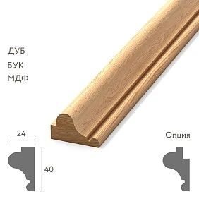
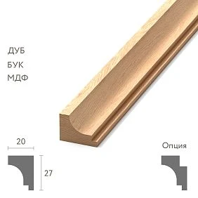
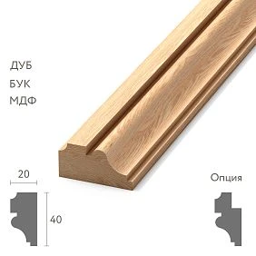
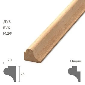
The design elevation and the actual wall are not the same thing
The architectural elevation drawing defines the design geometry. It is needed for composition, proportion coordination, placement of frames, doors, furniture, and other elements. But the procurement specification must account for the surface onto which the molding will actually be installed.
It is useful to distinguish between several states of the same wall.
Design dimension — the dimension in the approved documentation.
Construction base dimension — the geometry before finish leveling.
The dimension after plastering or another leveling layer — already closer to the real plane, but not always final.
Finished as-built dimension — the dimension between the actual architectural boundaries that will define the decorative composition.
For example, the design shows a wall of 4200 mm. After the partition is erected, 4210 mm may be obtained. After plastering and squaring two corners — 4194 mm. After installing the architrave, the decoratively available field may be even smaller.
For a frame system, it is often the last number that has practical significance.
This does not mean that the architect must redesign every wall after plastering. The point of the as-built measurement is different: to check how well the actual object fits into the adopted design system and whether one set can be safely replicated.
If the deviations do not affect the composition, the standard scheme is retained.
If deviations systematically change the side margins, the position of the frames relative to the door, or other noticeable elements, you need to change the adaptation rule first, rather than ordering thousands of linear meters based on the original figure.




Why even a small deviation becomes noticeable in a framed composition
A difference of 8–15 mm on an empty wall may be almost unnoticeable. But decorative layout creates a geometric system against which deviations read much more strongly.
Let's imagine a wall with two identical frames. A fixed gap is provided between them, and equal side margins on the outside.
If the actual wall is 20 mm narrower than the design and the frame sizes do not change, this difference needs to be distributed somewhere.
If only the left margin is reduced, noticeable asymmetry will appear.
If 10 mm is removed from each of the two outer margins, the composition will remain symmetrical.
If you start reducing the frames themselves without a single rule, identical numbers will stop being identical.
The same happens near the door.
The design opening could have been centered on the wall, but the actual outer edge of the casing has shifted. If the frames are positioned relative to the door, even a small shift can affect the composition more than a change in the overall wall width.
Therefore, the executive measurement always answers not only the question:
How much does the size differ?
You need to understand:
What exactly has changed, and which composition parameter accounts for this deviation?
This is what turns a measurement from a set of numbers into a manageable tool for wholesale procurement.
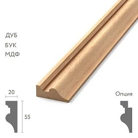
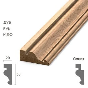
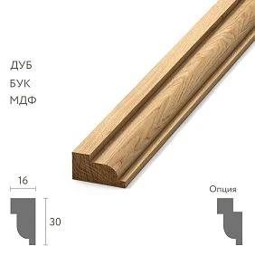
Our factory also produces:
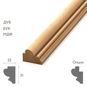
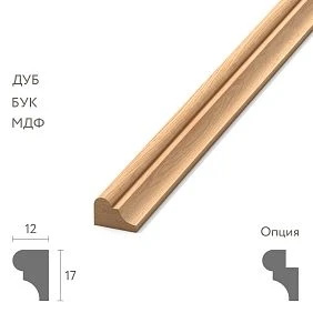
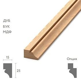
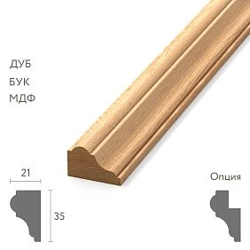
At what stage should the executive measurement be taken
Too early a measurement is useless: the surface will still be changing geometry.
Too late creates another problem: the molding is already needed by installers, while production or procurement is only just beginning.
Therefore, the control point is chosen after the work that forms the actual boundaries of the decorative field.
Depending on the project, the following must already be determined:
-
finished wall surfaces;
-
actual angles;
-
position of door units;
-
dimensions of future casings or casings already installed;
-
niches and projections;
-
wall panels;
-
built-in furniture, if it affects the frame composition;
-
baseboard or its exact top mark;
-
ceiling cornice or another upper architectural boundary.
This does not mean that all rooms must be fully completed.
For example, if the molding will be painted together with the wall, the finish coat may not yet be applied. But the geometry of the surface against which the frame is built must already be clear.
The correct question is:
can the following construction or finishing work still change the dimensions on which the placement of the molding depends?
If yes, it is too early to launch the final execution specification.
If not, you can proceed to the control sample.
Get Consultation
What exactly needs to be measured before a mass order
The mistake is reducing the executive measurement to a single wall width. For a frame system, this is almost never sufficient.
Overall width
It is measured between the finished boundaries that actually constrain the composition.
Most often this is a corner — a corner, but other options are possible: a panel, a column, a portal, a built-in wardrobe.
Decorative field height
Height "from floor to ceiling" is not always needed.
If a tall skirting board is installed at the bottom and a ceiling cornice at the top, the frame effectively lives between their working edges.
Therefore, it is more useful to record:
lower architectural boundary → upper architectural boundary.
Door position
You need more than just the width of the opening.
They record:
-
starting coordinate;
-
width;
-
height;
-
opening direction, if it affects furniture or the composition;
-
dimensions of the door casing;
-
the actual outer edge of the casing after installation.
Windows
They are especially important when the verticals of the frame system are built relative to the window axis or wall piers.
Niches, columns, and protrusions
They divide the wall into separate decorative fields and can change the width of the frames more than the overall wall deviation.
Built-in furniture
If a wardrobe, panel, or other built-in structure reaches the frame area, its position must be fixed before replication.
It is practically useful to create a small data sheet for each reference wall:
| Parameter | Project | Actual | Comment |
|---|---|---|---|
| Overall width | 4200 | 4192 | after finish plastering |
| Left edge of the door | 1280 | 1273 | along the outer edge of the casing |
| Width of the door unit | 980 | 992 | with casings |
| Top of the baseboard | 120 | 120 | without changes |
| Bottom of the cornice | 2800 | 2796 | actual elevation |
Such a table is much more useful than the phrase “the wall differs by 8 mm.”
A unified coordinate system reduces the number of errors
For a serial object, it is especially useful to assign a single zero to each wall.
For example:
left finished corner = 0.
Then all key verticals are recorded from a single point:
-
start of the door unit — 1273 mm;
-
first frame — from 260 mm;
-
composition axis — 2096 mm;
-
second frame — from 2310 mm;
-
right boundary — 4192 mm.
Why is this better than measuring each element from the nearest object?
Because a mixed coordinate system is difficult to verify.
One vertical is measured from the left corner.
Another — from the door.
The third — from the middle of the wall.
The fourth — from the cabinet.
If one number is wrong, it is difficult to find the source.
With a common zero, you can quickly check the arithmetic and see where each element actually is.
On long walls or in rooms with complex geometry, it is acceptable to use several local systems, but then their boundaries must be clearly documented.
The basic principle remains the same:
the coordinate must be reproducible by another specialist.
The installer, architect, order assembler and technical supervisor must all understand equally where the dimension comes from.
The design and the actual measurements need to be compared across several reference rooms.
A single measurement says nothing about the range of construction deviations.
For example:
| Room | Design width, mm | Actual width, mm | Deviation |
|---|---|---|---|
| 301 | 4200 | 4192 | -8 |
| 302 | 4200 | 4184 | -16 |
| 303 | 4200 | 4204 | +4 |
| 401 | 4200 | 4189 | -11 |
| 502 | 4200 | 4196 | -4 |
It is already clear that the real group is not equal to a single number of 4200 mm.
But the table itself still does not answer whether five different sets need to be made.
First, they check which parameters can accommodate this range without visually breaking the composition.
If the frames remain identical at all five values and the deviation is comfortably distributed between the side margins, one standard set may be acceptable.
If at 4184 mm the outer margin becomes visually too narrow, while at 4204 mm it is the opposite, there is grounds for two size groups.
That is why you cannot automatically turn every actual measurement into a new type.
An as-built survey is not needed to create a hundred unique specifications. Its purpose is to find a reasonable grouping system.
What should remain constant across a series of rooms
Before analyzing deviations, the architect or designer establishes a hierarchy of parameters.
Typically, several characteristics are kept consistent in a standard room.
Molding profile
In the case of a single room type, apartment type, or office type, the profile itself should not change from wall to wall just because of a minor construction deviation.
To select specific of wooden moldings first approve the SKU, material, and finish, and then calculate the specific lengths.
Frame height
In many serial interiors, the uniform height of frames creates a horizontal rhythm throughout the rooms.
If it changes on every floor, this can be more noticeable than a small difference in side margins.
Height of horizontal lines
When frames, panels, or bands run through a series of rooms, a single elevation helps maintain architectural discipline.
Principle of symmetry
If the composition is designed to be symmetrical, the installer must not be allowed to decide on their own which side to “hide” the missing millimeters.
Logic relative to the dominant element
In one room, the center of the wall may be the main element.
In another, it may be the door.
In a third, it may be the fireplace portal or a large built-in panel.
Therefore, the rule "always center on the wall" is not universal either.
Which parameters can be adjusted
Once the fixed parameters are determined, it becomes clear what can accommodate construction deviation.
Often these are:
-
outer side margins;
-
distance between groups of frames;
-
distance from the frame to the adjacent architectural element;
-
width of the outer decorative margins;
-
less often — the width of the frame itself, if provided for by the design.
Let's imagine two identical 900 mm frames on a wall.
Design wall — 4200 mm.
Actual — 4186 mm.
If the distance between the frames and their width are considered fixed, the missing 14 mm can be distributed equally across the outer margins: 7 mm on each side.
If the actual wall is 4204 mm, the outer margins increase by 2 mm each.
This way, a single standard frame can work within a small range of walls without creating a separate product for every millimeter.
But this is acceptable only when the designer considers the outer margins adaptive in advance.
If the key parameter is, for example, a strictly fixed offset from the door, the rule will be different.
The adjustment rule must be determined by the project, not by the installer
The installer can clearly see the actual wall, but should not redesign the architectural composition every time.
The procurement specialist also should not decide which frames to reduce in order to obtain a convenient cutting layout.
The designer's task is to turn an idea into a reproducible rule.
For example:
The central axis is fixed. The two main frames have a constant width. The deviation of the total wall width is distributed equally between the left and right outer margins.
Another option:
The position of the frames is fixed relative to the door portal. The free deviation is taken up by the margin at the opposite corner.
Third:
For an actual wall width from 4180 to 4195 mm, type TP-01A is used; from 4196 to 4210 mm — TP-01B.
Such rules make it possible to turn as-built measurements into a procurement system.
Without them, the wholesale batch exists only on paper, while the real design is created directly in the premises.
The control sample should show variation, not a perfect number
It is not necessary to immediately measure all one hundred identical rooms and create one hundred separate schemes.
First, a sample is needed that shows the character of the object.
It is reasonable to include the following premises in it:
-
on different floors;
-
in the end sections;
-
in the middle of the building;
-
at structural boundaries;
-
near expansion joints, if they affect the geometry;
-
in areas where another crew is working;
-
in zones with visually noticeable deviations.
The number of control rooms cannot be set as a universal figure. It depends on the size of the project, the repeatability of structures, the quality of the base, and the identified spread.
The main thing is not to limit yourself to a demonstration number.
A showroom or reference room is usually executed especially carefully. It showcases the design well, but poorly characterizes mass construction geometry.
For wholesale purchasing, you don't need the prettiest room—you need an honest picture of the range.
If ten control rooms show nearly identical dimensions, that's a strong argument in favor of a standard kit.
If they split into two stable groups, the project must acknowledge this before the batch is launched.
How to derive standard groups from as-built dimensions
Let's imagine a hotel with one hundred rooms of the same architectural type.
After the control measurement, it turned out that:
-
some walls fall within the range of 4182–4193 mm;
-
some — 4198–4207 mm;
-
individual rooms have more significant deviations.
Instead of one hundred unique layouts, you can create:
TP-01A — first geometric group;
TP-01B — second;
EXCL — rooms that require separate verification.
The groups differ not in style or molding article number. Only the actual geometry differs.
This provides several advantages.
First, serial production is preserved.
Second, the parts list remains manageable.
Third, the batch can be labeled by room type.
Fourth, a single wall defect does not break the system for the other ninety-nine rooms.
Grouping must be based on real architectural logic. You cannot create TP-01A and TP-01B solely for warehouse convenience if visually they produce different proportions that are not coordinated by the project.
Symmetry must be defined by numbers
Phrase:
position the frames symmetrically
conceptually clear, but insufficient for serial installation.
It is necessary to determine what the symmetry is built relative to.
For example:
-
wall axis;
-
axis of the doorway;
-
fireplace portal axis;
-
furniture composition axis.
After that, the coordinates are fixed.
If the center is a wall 4192 mm wide, its axis is at 2096 mm from the chosen zero.
Two frames can be positioned mirror-symmetrically relative to this axis.
If the door is offset and is the dominant element, the center of the wall may not be used as the main reference point at all.
This approach is especially important for wall moldings, because a decorative frame visually emphasizes the slightest misalignment of axes more strongly than a smooth painted surface.
After installing the door unit, the composition is checked again
On the design elevation, the door may be indicated by a single geometry.
On site, the decorative boundary is often defined not by the rough opening, but by the outer edge of the casing.
For example, the design left boundary of the door is 1280 mm.
After installing the frame and casing, the actual decorative boundary turned out to be at 1273 mm.
The difference is only 7 mm.
If the frame is built from the door, this is already a change in coordinate.
If there are two symmetrical groups to the right and left of the door, the error can be doubled.
Therefore, before starting a large batch, it is useful to check not only the opening, but also the entire future door system.
If the casing has not yet been installed, its dimensions must be known exactly.
You cannot measure only the clear opening and then discover that the casing takes up part of the decorative frame's field.
The baseboard and ceiling cornice define the actual height of the decorative field
The height of the frame is often mistakenly measured from the floor and ceiling.
But in a real interior, the lower boundary may be the top edge of the baseboard.
The upper boundary is the bottom edge of the ceiling cornice.
For example, the project specifies a lower frame offset of 180 mm from the floor.
If the actual baseboard is 120 mm high, it may be architecturally more correct to specify:
60 mm from the top edge of the baseboard.
Why is this more reliable?
Because if the finished floor level changes or the baseboard is replaced, the absolute dimension from the floor may no longer match the intended composition.
The same applies to the top.
Phrase:
200 mm from the ceiling
may be unreliable if the ceiling cornice has a complex projection and the actual visible lower edge is at a different point.
If the cornice is part of an architectural system, the frame grid should be tied specifically to it.
In the as-built schedule, it is useful to store not only dimensions but also the base dependencies:
bottom of the frame = top of the baseboard + approved offset;
top of the frame = bottom of the cornice - approved offset.
Corners after plastering have a particularly strong effect on short walls
Rough masonry may show one geometry, but after squaring the corners the usable width of the decorative field decreases.
On a long wall, a 10 mm change is usually easier to distribute.
On a short pier, the same 10 mm can noticeably change the proportion of the frame.
Therefore, control measurements must be taken at the finished corners.
If one corner has significantly “eaten” into the field, you need to determine the cause.
Various situations are possible:
-
ordinary construction tolerance;
-
thick leveling layer;
-
partition deviation;
-
incorrect geometry that still needs to be corrected.
Not every deviation should be accepted as a given.
If a wall clearly needs to be redone, it makes no sense to adapt an expensive decorative system to a defect that will be corrected later.
An as-built measurement does not replace substrate quality control.
A non-parallel wall requires a separate solution
Sometimes the width of a single decorative panel differs at the top and bottom.
For example:
-
at the bottom — 4190 mm;
-
at the level of the middle of the frames — 4184 mm;
-
at the top — 4178 mm.
In this case, the average value of 4184 mm by itself solves nothing.
The vertical sides of the frame emphasize the non-parallelism.
If they are installed strictly vertically, the gaps to adjacent corners will vary in height.
If you try to replicate the curvature of the wall, the frame itself will look visually incorrect.
First, the cause and acceptability of the substrate are determined.
If the deviation is within the limits accepted by the project design, the architect determines which line is considered the reference line.
If it is a finishing defect, the wall is corrected before installing the molding.
You cannot simply order parts "based on an average figure" and pass the problem on to the installer.
An as-built measurement is also a check of verticality
Molding creates long straight lines.
Therefore, a vertical profile can reveal a deviation that was almost unnoticeable on a painted wall.
The following areas are checked especially carefully:
-
near doors;
-
at tall wall panels;
-
at columns;
-
in the corners;
-
next to built-in wardrobes;
-
where the two frames should form a single rhythm.
For control, not only a tape measure and a laser distance meter are useful, but also vertical axes built with a laser level.
The point is not to turn a procurement article into a surveying manual.
The point is different:
part length and part position are different parameters.
A schedule where lengths are calculated correctly but coordinates are not defined does not yet guarantee the same result across a series of rooms.
Standard linear stock and a pre-cut set require different levels of precision
If ordinary linear stock of standard commercial length arrives at the site, part of the adaptation happens during on-site cutting.
The installer can receive, for example, whole strips of a single SKU and cut verticals and horizontals from them according to the approved scheme.
The requirements for as-built data remain high, but a small range of adjustments can be taken into account directly in the installation map.
A completely different situation is a pre-cut set.
If a batch is pre-assembled with parts of a specific length, an as-built dimension error immediately turns into an unusable part.
Therefore, pre-cutting is advantageous only after confirming real repeatability.
It is especially interesting when:
-
there are indeed many rooms;
-
the standard geometry is confirmed;
-
the set of frames repeats;
-
the finish and SKU are stable;
-
marking is organized by types.
Pre-cutting is dangerous when the project treats rooms as identical, but the control measurement shows a wide variation.
In that case, the desire to prepare the kit as fully as possible at the factory can increase the number of reworks.
The parts list is more important than the overall line in linear meters
After approving the room types, you need to move from the overall footage to specific parts.
Example:
| Part code | Article | Length, mm | Quantity | Room Type |
|---|---|---|---|---|
| V-01 | MLD-X | 1600 | 200 | TP-01A |
| G-01 | MLD-X | 900 | 200 | TP-01A |
| G-02 | MLD-X | 1100 | 100 | TP-01B |
Here:
V — vertical part;
G — horizontal.
The codes are arbitrary. A project may use its own system.
The main thing is that the line:
MLD-X — 1200 meters
turns into a set of parts that actually need to be obtained from stock boards.
This allows:
-
build cutting map;
-
assess usable offcuts;
-
create pre-cut sets;
-
place accurate reorders;
-
verify the completeness of the first phase.
At this stage wholesale purchase of building materials becomes a manageable specification rather than a general budget figure.
The outer frame size, inner sight size, and part length must not be mixed up
One of the most dangerous mistakes is to write in the schedule:
frame 900 × 1600 mm
and not specify what this figure means.
A frame can have at least several size systems.
Outer dimension — the size along the outer edges of the moulding.
Inner sight size — the free field inside the frame.
The length of each part — the actual length of the bar according to the accepted cutting and joining system.
These values are related to the profile width and the method of forming the corners.
Therefore, the executive specification must have a separate field:
frame measurement system.
For example:
All frame dimensions are specified by outer dimension.
Or:
The size is given by the inner sight field; part lengths are provided in a separate list.
Without such a note, one team may treat 900 mm as an internal dimension, while another treats it as an external one.
In a bulk order, the error will be repeated throughout the entire batch.
The cutting map is built only after the actual lengths of the parts are fixed
Calculating the total linear meterage of the molding is useful for an initial estimate, but it is not enough for purchasing.
Let's imagine that 1000 linear meters are needed.
This number does not show how many whole commercial strips will be required.
The reason is the structure of the parts.
from one plank you can get:
-
one long vertical and a short remainder;
-
two medium horizontals;
-
several short elements.
Therefore, a parts list is formed first.
Then specific lengths are distributed across commercial bars.
For each SKU, its actual available length in the selected variant is checked. It cannot be assumed in advance that all Trimming Items have the same commercial length.
In the cutting map, long critical parts usually get priority.
Short elements are then placed in usable remnants.
This is more important than mechanically adding one percent of waste to the entire volume.
Typical parts make it possible to turn remnants into a resource
A serial object provides a major advantage: short parts repeat.
After cutting a long vertical, a section may remain that is ideally suited for the horizontal of another frame.
If the bill of materials is built by part codes, such possibilities are visible in advance.
For example:
-
В-01 — 1600 mm;
-
Г-01 — 900 mm;
-
Г-02 — 450 mm.
The remainder after one operation can cover Г-02.
But remnants must be used systematically.
You cannot rely on a random phrase:
the installers will pick something later.
For a large batch, useful remnants must be part of the cutting map.
This allows reducing unnecessary orders without the risk of an incomplete set.
The system works especially well when several typical rooms use the same wooden molding.
If the material or finish differs, the remnants between such groups are not merged automatically.
A wholesale batch is best divided by room types and installation zones
Even if the entire project uses one profile, the warehouse logic must preserve the origin of the material.
For example:
building A / floor 4 / TP-01A / MLD-X
Or:
building B / rooms 201–220 / TP-01B / MLD-X.
Such a code can be used on a pack, set, or issue sheet.
Why is this needed?
If all the molding is stored as one common mass, the first-phase contractor can easily use up the parts for the second.
This is especially dangerous with pre-cut sets.
A vertical V-01 with a length of 1600 mm may look almost the same as V-02 with a length of 1585 mm.
The difference is barely noticeable to the eye.
Once the frame is installed, it becomes a height violation.
Therefore, different room types cannot be mixed just because the profile is the same.
The article number describes the product.
The standard kit code is its specific application.
The first installation batch should become the control batch, not just the first one.
Even a carefully prepared as-built model needs to be verified on site.
Therefore, it is useful to treat the first few rooms as a control batch.
After installation, check:
-
whether the actual geometry matches the sample;
-
whether the side margins are preserved;
-
is the adaptation rule working correctly;
-
are the part lengths suitable;
-
is the marking convenient;
-
are the external and internal dimensions not mixed up;
-
does the cutting plan match the actual work;
-
is there no systematic shortage of a single part.
If everything is confirmed, the next volume is launched.
If a recurring error is detected, you cannot continue another eighty rooms with manual correction.
It is necessary to stop replicating the defect and update the standard scheme.
This is one of the main advantages of a serial system: the correction is made in the model, not a hundred times on the wall.
A systemic error and an isolated error require different responses
Let's imagine that in the first batch of ten units, eight have the same problem: the outer edge is 12 mm narrower than the calculated value.
This is a sign of a systemic defect in the model.
Possible causes:
-
the actual boundary was determined incorrectly;
-
the casing size differs from the design;
-
the zero point was set incorrectly;
-
one frame parameter was mistakenly considered constant.
In this case, TP-01 is updated.
Another situation: nine units match, but one has a wall 35 mm narrower due to a local construction deviation.
This is an exception.
There is no need to change the entire standard set because of it.
The room receives a separate status and its own adjustment.
This way, serial production is preserved, and real deviations are not ignored.
It is better to place a reorder by part codes, not by linear meters
Phrase:
another 100 meters of MLD-X
too weak.
It does not explain exactly what was missing.
It is possible that there is stock in the warehouse, but the long verticals have run out, and the remaining pieces are too short.
Therefore, a correct reorder looks, for example, like this:
-
V-01 — 12 pcs.;
-
G-02 — 8 pcs.;
-
type TP-01B;
-
item MLD-X;
-
material and finish according to the current specification.
After that, it is calculated how many product strips will be needed to manufacture the missing parts.
Such a system simultaneously helps analyze the cause of the shortage.
If G-02 is constantly reordered, perhaps the cutting map was inefficient.
If B-01 is regularly in short supply, perhaps the initial number of rooms turned out to be incorrect or a systemic defect has appeared.
Reordering becomes a source of feedback, not just an emergency purchase.
Practical scenario: one hundred hotel rooms
Let us consider a hypothetical property.
The architect designed 100 identical rooms.
On the main decorative wall there are two vertical frames made from the same profile.
Design wall width:
4200 mm.
At first glance, procurement can take the design layout, calculate the perimeter of the frames, multiply by 100, and order a batch.
But before launch, an as-built measurement of ten rooms is performed.
The following values were obtained:
| Number | Actual wall width, mm |
|---|---|
| 201 | 4186 |
| 202 | 4194 |
| 203 | 4203 |
| 204 | 4179 |
| 301 | 4188 |
| 302 | 4191 |
| 401 | 4201 |
| 402 | 4198 |
| 501 | 4183 |
| 502 | 4205 |
At the same time, the position of the doors and door casings is checked.
It turns out that most of the rooms fall into two stable groups.
The first is suitable for the type:
TP-01A.
For the second:
TP-01B.
Number 204 has a separate local wall deviation and is placed in the exception.
After this, the designer establishes the rule:
-
the profile is the same;
-
the frame heights are the same;
-
the position relative to the door is preserved;
-
a small difference is distributed between the outer margins;
-
the two geometric groups have different horizontal parts.
Next, the statements are generated.
TP-01A
| Code | Purpose | Length | Quantity per number | |||||||||||||||||||||||||||
|---|---|---|---|---|---|---|---|---|---|---|---|---|---|---|---|---|---|---|---|---|---|---|---|---|---|---|---|---|---|---|
| V-01 | Vertical | According to the approved scheme | 4 | |||||||||||||||||||||||||||
| G-01 | Horizontal | According to the approved scheme | 2 | |||||||||||||||||||||||||||
| G-02 | Horizontal |
According to the approved scheme
This is especially important when Wholesale building material suppliers they receive one large order for several cabinets. The internal specification must preserve an understanding of where the quantity came from. How to account for molding finishThe finished size and the finish are different parts of the specification. One geometry type can exist in several colors. For example: TP-01A / O-01 и TP-01A / O-02. If the profile and lengths are the same, the parts map matches, but the purchasing items after the final finish are no longer interchangeable. Therefore, in the bill of materials, it is advisable to store next to the part code:
The remainder of one finish cannot be automatically sent to another group just because the length fits. If the molding is supplied without a finish and is painted on site, the system may be different. But this must be explicitly recorded. How to compare supplier offersThe wholesale request must contain the same initial specification for all participants. It is not enough to send:
One supplier may count whole product planks. Another — net linear meters. A third — material in a different finish. The fourth — without accounting for configuration by types. Therefore, offers are compared only after aligning the composition. At minimum, the following must match:
If considering building materials at wholesale prices, a low price per meter by itself does not yet show the cost of covering the object's needs. The as-built measurement log must store the origin of each figureOn a large site, it is dangerous to work with a table that contains only final dimensions without reference to the room, date, and readiness stage. For example, the line:
does not allow understanding when the figure was obtained and whether it can be trusted after the next finishing revision. It is more useful to keep a log in which the following is recorded for each control wall:
Example structure:
Such a log serves two purposes. The first is to verify where a typical group came from. The second is to prevent mixing dimensions from different stages. If one specialist measured before casing installation and another after, their figures cannot be blindly combined into a single sample. The geometric difference may not be construction variance but a consequence of different measurement conditions. For a large order, this is critical. A wholesale specification cannot be built on a dataset where different rows measure different physical boundaries. The acceptable range should be a design rule, not random statisticsAfter measuring, it is easy to get an average value and decide that all walls around the average are "roughly the same." This cannot be done. Statistics show the spread, but do not determine architectural acceptability. For example, most walls fall within the range of 4188–4198 mm. This does not yet mean that a standard set automatically fits the entire range. The extreme cases need to be checked. Suppose that at 4188 mm the edge margin is 115 mm, and at 4198 mm it is 120 mm. The difference is visually acceptable and has been agreed with the designer. Then the range can be combined. But if on a short wall section the same 10 mm reduces the margin from 55 to 45 mm and disrupts the intended proportion, a single set may already be unacceptable. Therefore, the type range is not formed by a formula: average ± a few millimeters. It is formed by checking: minimum actual geometry → composition acceptable? maximum actual geometry → composition acceptable? If both edges work, intermediate values are usually easier to control. If one edge does not work, the typical group needs to be narrowed or the adaptation rule changed. Before ordering, it is necessary to freeze not only the dimensions, but also the version of the systemA large project rarely remains unchanged from the first sketch to installation. After the as-built survey, the designer may change:
If the new version is not explicitly documented, procurement may send an outdated table to the supplier. Therefore, the standard set must have a revision. For example: TP-01A / revision 3. The revision card records:
Particularly dangerous file names:
For a wholesale batch, there must be one active version unambiguously linked to the order. If the size of G-02 changes after production starts, the project must understand whether the change applies to a batch not yet produced or requires a separate decision for already finished parts. How to convert a parts list into actual purchasing quantitiesOnce the standard parts are approved, a proper calculation of complete products can be performed. Let's look at a simplified example. For 50 rooms of type TP-01A, the following is required per room:
Total parts required: V-01: 4 × 50 = 200 pcs. G-01: 2 × 50 = 100 pcs. G-02: 2 × 50 = 100 pcs. Net length: 200 × 1.6 = 320 m; 100 × 0.9 = 90 m; 100 × 1.1 = 110 m. Total: 520 m of net parts. But ordering 520 m of linear stock does not yet mean obtaining a sufficient number of whole strips. Suppose the selected product variant has a length confirmed for a specific SKU, and the cutting plan shows that a combination of several parts can be obtained from one strip. Then the purchase quantity is determined precisely by the cutting plan. For example, long B-01 items are allocated first. The remnants are analyzed for G-01 and G-02. If some of the remnants are too short or geometrically inconvenient, the net 520 m turns into a larger purchase volume. This is exactly where the difference between the two concepts becomes apparent: the net linear meters of parts and the linear meters of purchased whole items. For a commercial proposal to the supplier, it is better to provide either the ready quantity of product strips or the full set of part lengths if the manufacturer is to calculate the cutting plan. Why the reserve cannot be added before the cutting planPeople often try to calculate the reserve right away:
This is simple arithmetic, but it does not account for the structure of whole products. If the cutting map already creates a certain technological remainder, an additional percentage may turn out to be excessive. The opposite situation is also possible: 10% in meters looks sufficient, but does not yield the required number of long parts. Let's imagine that after installation you need to have a reserve of four verticals V-01. The warehouse may hold 12 meters of short offcuts, but none of them allows you to obtain a 1600 mm vertical. Formally, the reserve in linear meters exists. Functionally, the required part is not there. Therefore, it is better to define the reserve through real risks:
The method depends on the project, but the reserve must allow for actually restoring a damaged frame, not just look good as a percentage. The connection between the molding and the wall panels must be checked separatelyIn the project, the frame may be on a painted wall, with a built-in panel or boiserie next to it. If the panel is installed after plastering, it can change the actual boundary of the field even after a standard wall measurement. For example, the design composition was built up to the vertical line of the panel. After installation, its visible edge shifted by 12 mm relative to the rough layout. If the molding has already been cut, the outermost frame will end up closer to the panel than intended. Therefore, for moldings for wall panels the as-built boundary must take into account not only the wall plane, but also the actual visible edge of the adjacent system. In the wall inspection passport, it is useful to note:
This way, two independently correct systems — the panel and the molding — do not come into conflict during installation. Changing one standard room must go through an assessment of the impact on the entire batchLet's imagine that after installing the first five rooms, the designer asks to increase the top offset of the frame by 20 mm. On one wall, the change seems small. In a wholesale batch, it can affect:
Therefore, any change to a standard solution undergoes a quick impact check. You need to answer:
If the change only affects the installation coordinate with the same parts, procurement may not change. If lengths change, this is no longer just a design adjustment — it is new procurement information. Acceptance of a wholesale batch must verify completeness by typesIf an order consists of standard kits, accepting it only by total length or number of packs is not enough. For example, 1000 units of parts were delivered, and the total matches the invoice. But for TP-01A, 20 verticals V-01 are missing, and for TP-01B, 20 extra horizontals were delivered. The total quantity is perfect. Installation readiness — no. Therefore, control is performed at a minimum of two levels. Product controlChecked:
Kit controlChecked:
This way, the warehouse sees not just the quantity of molding, but the actual readiness of the rooms. When a mass order is better postponedThere are situations when you can formally calculate the linear meters, but it is too early to launch the main batch. It is better not to freeze the order if:
Under such conditions, early procurement does not speed up the project. It transfers uncertainty from the drawing into physical material, which will then have to be reworked or stored. for construction materials wholesale from the manufacturer unambiguity of the specification is especially important: a large batch should be launched only after its parameters are truly frozen. How to organize the transfer of data from the surveyor to procurementEven a good as-built measurement can be lost during handover between teams. The surveyor works with millimeters and coordinates. The designer — with proportions and standard solutions. Procurement — with SKUs and quantities. The warehouse — with packs and labeling. The installer — with specific parts on the wall. If each team receives a separate table without a common identifier, there is a risk of desynchronization. It is useful to use a single code chain: object → room → wall → type → part → SKU → revision. For example: A / 4 / 412 / С-02 / ТП-01А / В-01 / MLD-X / Р3. It is not necessary to print the entire code on every strip. But it must exist in the document system and make it possible to trace the path of the part from the wall to the order. It is precisely this kind of traceability that sharply reduces the risk of mix-ups when several floors and several installation crews are being worked on at the site at the same time. Eighteen mistakes when ordering molding wholesale based on as-built dimensions1. Ordering from the architectural elevation without checking actual conditionsWhy it happens: the project has already been approved and seems final. Consequence: the actual walls do not match the framing grid. How to prevent: perform a control as-built measurement before mass ordering. 2. Measuring only one ideal roomWhy it happens: it is convenient to use as a reference. Consequence: the real range of the object remains unknown. How to prevent: select control rooms from different zones and floors. 3. Measuring too earlyWhy it happens: there is a desire to start procurement in advance. Consequence: plaster, corners, or openings are still changing the geometry. How to prevent: define a construction control point. 4. Measuring only the wall widthWhy it happens: the frame is perceived as a rectangle within the overall field. Consequence: the position of the door or niche breaks the composition. How to prevent: fix the coordinates of all architectural boundaries. 5. Not accounting for door casingsWhy it happens: the structural opening is measured. Consequence: the outer edge of the door unit ends up closer to the frame than expected. How to prevent: use the actual or precisely known dimensions of the door casing. 6. Not accounting for the baseboardWhy it happens: the vertical dimension is measured from the floor. Consequence: the bottom margin of the frames differs after the baseboard is installed. How to prevent: bind the decorative field to the top edge of the baseboard if the project is built that way. 7. Ignoring the ceiling corniceWhy it occurs: the top offset is set from the ceiling. Consequence: the actual visible interval does not match the project. How to prevent: use the actual architectural boundary. 8. Making every room unique without range analysisWhy it occurs: each execution dimension is treated as a separate type. Consequence: the specification grows to hundreds of variants. How to prevent: first look for stable geometric groups. 9. Leaving adaptation to the installerWhy it happens: it is assumed that the specialist will “figure it out on site.” Consequence: different solutions appear in identical rooms. How to prevent it: approve the adjustment rule in advance. 10. Not defining fixed parametersWhy it happens: all dimensions are considered equally flexible. Consequence: frames, indents, and axes all change at the same time. How to prevent it: establish a hierarchy: what is fixed and what is adaptive. 11. Confusing the outer and inner dimensions of the frameWhy it happens: the documentation only says “900 × 1600.” Consequence: different teams get different part lengths. How to prevent: sign off on the size system. 12. Not accounting for length at cut pointsWhy it happens: the overall dimension is mistakenly taken as the length of the strip. Consequence: parts do not assemble into the required geometry. How to prevent: issue a separate parts list. 13. Counting only linear metersWhy it happens: linear meters are convenient for budgeting. Consequence: it is impossible to create an accurate cutting plan. How to prevent: switch from linear meters to lengths and part quantities. 14. Not building a parts listWhy it happens: they plan to cut everything on site. Consequence: it is harder to control consumption and reordering. How to prevent it: assign codes to repeating verticals and horizontals even when cutting on site. 15. Mixing room types in the warehouseWhy it happens: the profile and finish are identical. Consequence: parts of similar lengths end up in the wrong rooms. How to prevent it: keep the standard kit code in the labeling. 16. Not checking the first installation phaseWhy it happens: after the specification is issued, the task is considered complete. Consequence: a systemic error is replicated across the entire site. How to prevent: the first batch must end with a control check. 17. Continue installation after discovering a recurring errorWhy it happens: they try not to stop the schedule. Consequence: dozens of rooms get the same defect. How to prevent: fix the standard scheme before continuing the series. 18. Place reorders only in linear metersWhy it happens: it's faster to formulate the request that way. Consequence: generic material arrives, but the required lengths are still insufficient. How to prevent: reorder specific part codes. Checklist before launching the main batchBefore finally purchasing molding wholesale for a large project, not only the article number and total linear footage must be determined. Check:
If half of this data exists only "in the head" of a specific installer or designer, the wholesale batch is not yet ready for launch. What the final ordering system should look likeFor a serial object, it is useful to go through the entire path in a single sequence. PROJECT LAYOUT → READINESS OF FINISH GEOMETRY → CONTROL AS-BUILT MEASUREMENT → COMPARISON OF PROJECT AND ACTUAL → ADAPTATION RULE → TYPICAL ROOM GROUPS → COORDINATE SYSTEM → FRAME SCHEDULE → PARTS LIST → CUTTING MAP → PURCHASE QUANTITY → MARKING → FIRST CONTROL BATCH → ADJUSTMENT IF NEEDED → MAIN WHOLESALE BATCH → STOCK CONTROL → REORDER BY PART CODES This approach preserves the main advantage of a serial interior — repeatability — while also accounting for the actual construction geometry. Wholesale purchasing of moulding becomes truly effective not when the total linear footage is simply multiplied by the number of rooms, but when the project knows in advance which parts repeat, which deviations are acceptable, and by what rule each actual wall becomes one of the approved standard kits. Then finishing material suppliers they receive an unambiguous specification, the warehouse understands the purpose of the batch, installers work within a single coordinate system, and a single wall deviation does not turn the entire project into a hundred different design solutions. For a large order, this is the main readiness criterion: not just knowing how many meters of moulding are required, but being able to reproduce one approved architectural system across the entire project without mix-ups, random fitting, and constant emergency reorders. |