











































Article Contents:
- What is a DWG of a decorative slat and why does a designer need it
- A slat and a slatted panel are not the same thing
- Individual decorative slat
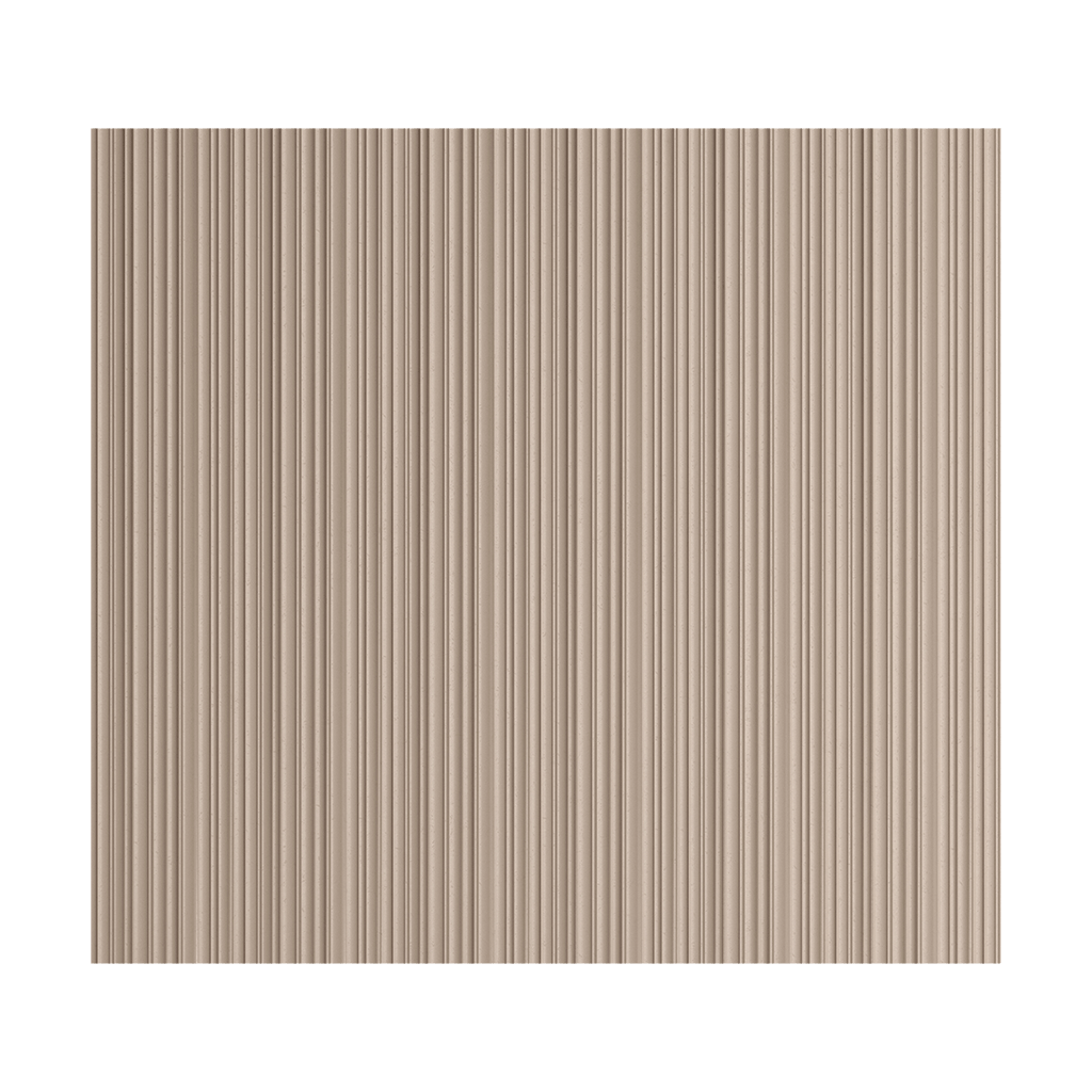
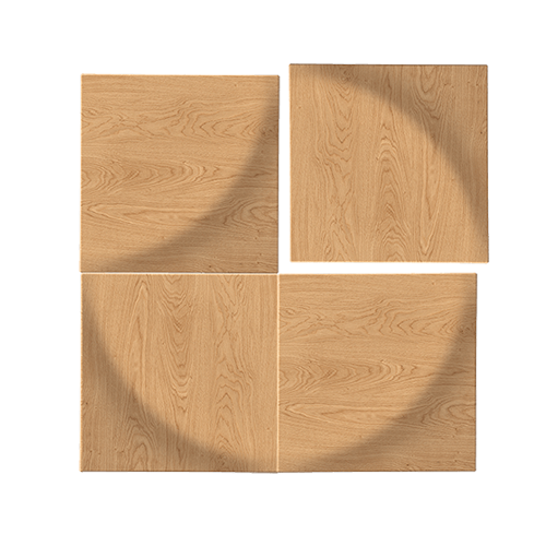
- Finished slat panel
- Centered layout
- Layout from the edge
- Plan
- Facade
- A slat is drawn in the DWG without an SKU
- Only the pitch is specified
- The last slat has not been checked
- Sockets are shown over the slats conventionally
- The slat is scaled in CAD
- The slatted partition is shown only as a facade
- The panel is counted as a set of individual slats

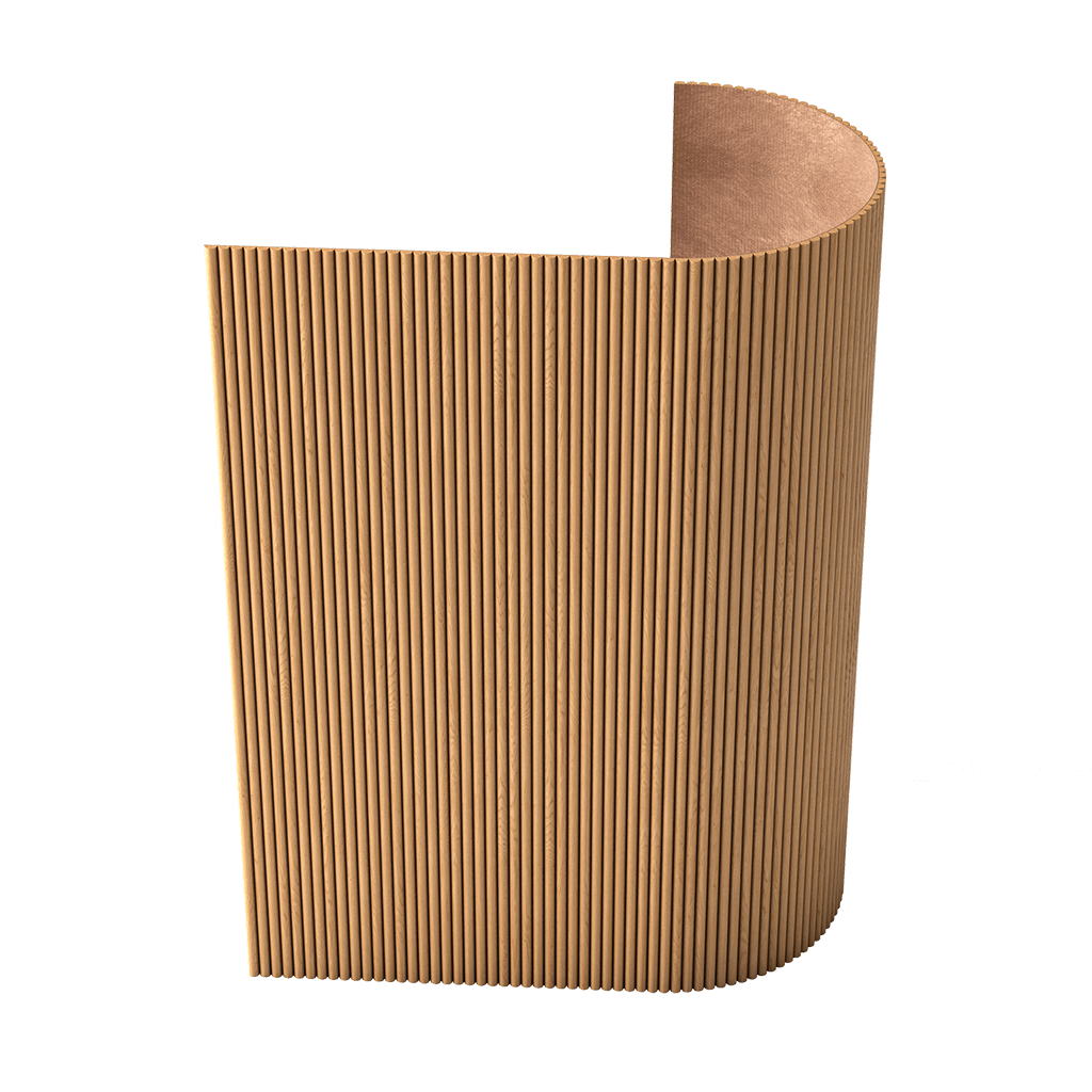
In a visualization, a slatted wall often looks simpler than in working documentation. The rhythm is even, the verticals are neat, and the edge elements are almost invisible. But once you move from the render to the drawing, it turns out that a decorative slat is not a line on a facade. It has an actual width, depth, length, mounting side, material, a specific SKU, and a real way of adjoining to a door, baseboard, ceiling, or furniture.
That is why decorative slat DWG files are needed not as a pretty block library, but as a way to tie the visual concept to the physical product. If AutoCAD contains only evenly spaced vertical lines, the project still does not answer the main questions: which slat will be purchased, what its cross-section is, what the gap between elements is, how the spacing is calculated, what happens in the last module, and whether an outlet lands exactly in the middle of the profile.
The working logic should follow a different order:
SKU → actual cross-section → DWG → layout base → spacing and gap → edge slats → details → quantity → specification → order.
In such a project, the installer does not "divide the wall roughly evenly" on site. The composition is resolved in advance, and the DWG becomes the link between the catalog and the working documentation.


What a decorative slat DWG is and why a designer needs it
A DWG file is useful when it captures the geometry of the actual product. This is a fundamental point.
A slat in a working project is not a conventional vertical line, but a physical profile. At minimum, the following must be known for it:
- actual width;
- actual depth;
- cross-section shape;
- orientation of the mounting side;
- scale 1:1;
- link to a specific SKU.
If these parameters are unknown, the designer is drawing not a product, but an intention.
For an initial visual concept, this is sometimes enough. For issuing working documentation — no longer.
For example, two profiles may read the same in the front view but have different depths. In the unfolded view, this is almost imperceptible. In a real interior, one profile will cast a light shadow and almost blend with the wall, while the second will become a pronounced volume and begin to conflict with the casing, cabinet facade, or socket frame.
Therefore STAVROS decor DWG should be used not as conventional graphics, but as the technical basis of the design solution.
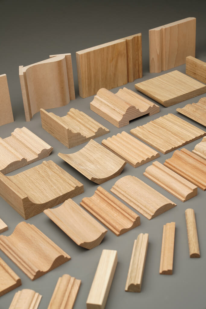



A slat and a slatted panel are not the same thing
In a project, these two solutions are often visually similar, but they are calculated differently.
Our factory also produces:
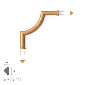
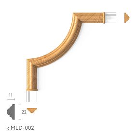



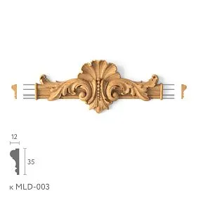
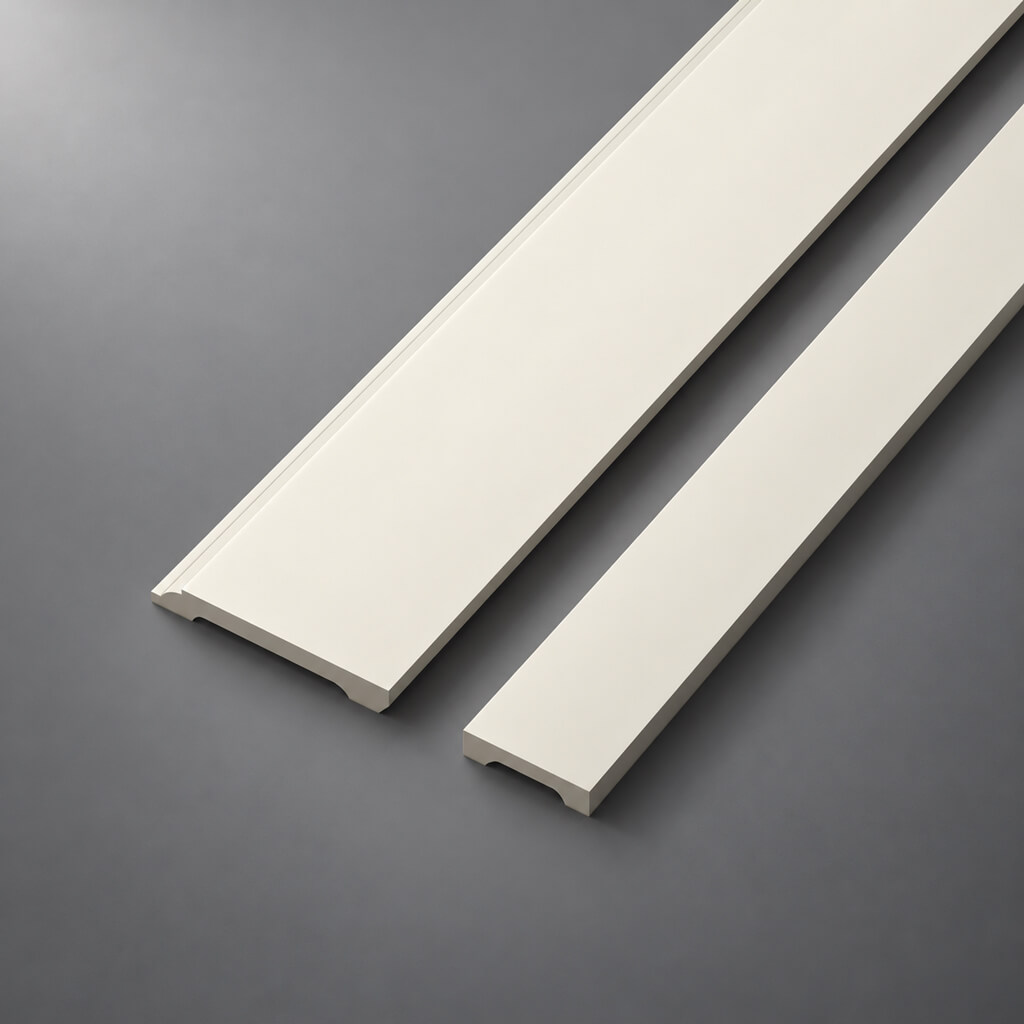
Separate decorative slat
If individual slats are used, the designer determines the following:
- spacing;
- the gap between slats;
- quantity;
- the start and end of the field;
- the alignment to the architectural axis;
- base;
- the method for handling corners and openings.
In effect, the designer builds the rhythm manually.
Get Consultation
Finished slat panel
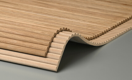
With a ready-made panel, part of the logic is already built into the product module. The rhythm, the distance between protrusions, the width of the base, or the repeating fragment can be set by the design.
Therefore, you cannot take the calculation method for an individual slat and mechanically transfer it to Rafter panels.
For an individual slat, the repetition of physical profiles is calculated. For a panel, it is the layout of ready-made modules and cut-offs.
These are different tasks, even if in the render both surfaces look like a row of vertical wooden strips.
What slat dimensions should be known before layout
At minimum — width × depth × length.
But for working documentation this is often not enough. It is additionally useful to know:
- cross-section shape;
- radii or chamfers;
- the location of the face side;
- the mounting plane;
- the material;
- the direction of the grain, if natural wood is used;
- the specified finish;
- SKU;
- the actual commercial length.
Why is length also important if the slats on the facade run from floor to ceiling?
Because the visual height of the area and the commercial length of the product are not the same thing. If the profile is shorter than the design height, a joint appears. If it is longer, cutting and leftover material occur. For a wooden element, the position of the joint can be visually noticeable, especially on a repeating wall.
Before starting the layout, the designer must understand exactly what they are laying out.
Why you can't design slats using lines alone
A line has no thickness. A slat does.
Let's assume an axial spacing of 50 mm.
Option 1:
- slat width — 10 mm;
- clear gap — 40 mm.
Option 2:
- slat width — 30 mm;
- clear gap — 20 mm.
The axes coincide. The number of elements across the same wall width may also be similar. But visually, these are two completely different surfaces.
In the first case, the wall will be perceived as airy, with a strong presence of the background. In the second, the wood or painted profile will occupy most of the field, and the slatted structure will become dense.
If only the lines along the axes are left in the working file, this difference disappears.
Therefore, for detailed layouts it is advisable to show at least the overall dimensions of the slat, and in a typical detail, its actual cross-section.
Width, gap, and pitch are three different parameters
These values are easy to confuse, especially when the rhythm is set by a short note on the drawing.
The width of the slat is the physical size of the product along the front.
The gap is the clear distance between adjacent slats.
Pitch is the repeating distance between identical points of elements, usually between axes.
For a rectangular slat with uniform layout, we can write:
pitch = slat width + gap.
But in a working drawing, it is better not to force the installer to reconstruct one value from another. If both the pitch and the clear gap are critical for implementation, they should be shown.
This is especially important with a wide profile. The difference between the phrases "slats every 60 mm" and "60 mm gap" can completely change the quantity and appearance of the wall.
How to set slats on a wall elevation
A good elevation should answer not only the question "where the slats are placed", but also "what they are built from".
It is useful to show on the drawing:
- boundaries of the slat area;
- base axis;
- first rail;
- last rail;
- repeating pitch;
- actual profile width;
- clean margins at the edges;
- openings;
- Furniture;
- sockets and switches;
- plinth;
- ceiling boundary.
The phrase "slats with equal spacing" is insufficient.
Equal spacing can be achieved in dozens of ways. Where will the first slat be? At the center of the wall? On the TV axis? From the edge of the cabinet? From the door casing? With what margin will the composition end?
If this is not defined in the design, the decision is deferred to the construction site.
Where to start the layout
A slatted composition must have a base.
It can be:
- center of the wall;
- the axis of the room;
- the edge of the doorway;
- the axis of the furniture;
- center of the TV;
- niche edge;
- architectural axis of the panel;
- line of junction with the cabinet.
The choice of base depends on what a person actually perceives as the main element of the composition.
Let's imagine a wall 4.2 m wide. On the left is a built-in cabinet with a depth spanning the full height of the room, on the right is a doorway. The geometric center of the entire wall may be useless, because the visible area between the cabinet and the door is already asymmetrical.
In that case, it is more correct to anchor the slats to the actually perceived field.
First the base. Then the rhythm.
Center the slats or start from the edge
There is no universal answer.
Centered layout
It is logical if the composition is symmetrical:
- TV zone;
- pier between two identical openings;
- central decorative panel;
- symmetrical wall in the hallway.
Here the center is a natural reference point.
Layout from the edge
It is often more rational near:
- a built-in wardrobe;
- Doors;
- niches;
- an outer corner;
- an abutment to another finish.
For example, if the batten must start at a specific 40 mm from the casing, that reference point matters more than the conventional symmetry of the entire wall.
But laying out from the edge has a mandatory check: what will happen on the opposite side?
It is the last slat that most often shows that the original scheme does not work.
Why the edge slat matters more than the middle one
In the center of the field, the repeating rhythm almost always looks calm. Errors occur at the edges.
Typical problems:
- the last slat ends up too close to the corner;
- a narrow random gap remains;
- the slat falls halfway onto the casing;
- a “cut-off” module forms near the cabinet;
- the edge slat conflicts with the switch;
- after turning the corner, the rhythm breaks.
Therefore, a proper layout check is not only looking at the average spacing, but also carefully examining the two edge zones.
If the center is beautiful but the edges are random, the project is not finished.
What to do if the last slat doesn't fit
Automatically cutting it in half lengthwise is a bad solution if it wasn't part of the concept.
There are several options:
- slightly change the spacing;
- change the margins at the edges;
- shift the base axis;
- change the width of the slatted area;
- finish the composition earlier;
- switch to another profile if the task allows for replacement.
Which option is correct depends on the specific wall.
For example, after calculation, 18 mm remains on the right. If the entire project is built on a 30 mm wide slat, the edge element with a width of 18 mm will look like a mistake, even if technically it can be ripped down.
Sometimes a solution with two identical margins at the edges and a slightly adjusted gap looks much stronger.
But this adjustment must be calculated and shown in the project, not improvised by the installer on site.
Slatted wall and doorway
The door is one of the first junctions where the real depth of the slat becomes apparent.
Need to check:
- width of the door casing;
- the thickness of the casing;
- depth of the slat;
- reveal;
- the clean field between the casing and the first batten;
- baseboard position;
- the upper boundary of the composition.
This is especially noticeable when the decorative batten protrudes from the wall more than the casing.
On the frontal elevation, everything may look flawless: parallel verticals and a neat field near the door. In profile, it turns out that the batten physically extends forward relative to the door opening trim.
Sometimes this is acceptable. Sometimes it looks accidental.
A cutaway is needed.
Batten and concealed door
A concealed door changes the very logic of a batten wall.
There are at least three scenarios here:
- the battens end at the edge of the door leaf;
- the door is integrated into the overall rhythm;
- the slats continue across the door leaf.
The third option is visually strong but technically the most demanding.
Need to check:
- opening;
- gaps;
- the mass of decorative elements;
- hinge position;
- the handle;
- the slat passing across the boundary of the door leaf;
- matching the rhythm in the closed position.
If the door leaf is to visually disappear into the wall, even a slight shift of one slat after adjusting the door will become noticeable.
Therefore, such a scheme cannot be left only in the visualization. It must be worked out in the working project.
Slats and a built-in wardrobe
Built-in furniture creates a similar problem.
Check:
- the side panel;
- facade;
- opening trajectory;
- depth of the slat;
- gap between the slat and the furniture;
- the last axis;
- plinth;
- ceiling junction.
A slat drawn over the facade on a beautiful elevation can physically obstruct opening.
Push-to-open facades and doors without protruding handles are especially risky: visually the furniture looks flat, so the designer easily forgets about the actual trajectory of the panel.
Slatted finishing must account for furniture as a volume, not as a line on the facade.
Slats and skirting
The lower junction must be determined before the project is released.
Different layouts are possible:
- the slat goes all the way to the floor;
- the slat starts from the top edge of the skirting;
- the skirting board runs in front of the slats;
- the skirting board is interrupted in the slat area;
- the slat and skirting board form a single unit.
Visually, the difference is huge.
If a tall skirting board runs continuously, it becomes the lower horizontal band, and the slats begin to work above it. If the verticals reach the floor, the composition is perceived as more cohesive and taller.
There is no universally better option. But it must be chosen in advance.
On the section, show:
- the height of the baseboard;
- its projection;
- depth of the slat;
- the actual junction.
Slats and ceiling
The upper mark seems obvious only in the render.
On the working drawing, you need to check:
- final height;
- stretch or drywall ceiling;
- shadow profile;
- cornice;
- niche;
- lighting;
- actual length of the rail.
If the room has a ceiling cornice, the rail can:
- reach its lower edge;
- go behind it;
- stop at the field;
- fit into a specially designed groove.
Each pattern produces a different geometry.
At nodes with a shadow gap, it is especially important not to substitute the real elevation with a conditional height from the visualization.
Sockets and switches on a slatted wall
This is one of the most common points of conflict.
The rosette can:
- fit entirely into the gap between slats;
- cross one slat;
- land on two at once;
- require a decorative backing;
- disrupt the regular rhythm.
A bad scenario is discovering this after most of the wall has been installed.
A good one is to combine the electrical plan with the slatted layout before release.
Sometimes it is easier to shift the engineering point by a few centimeters. Sometimes it is better to slightly adjust the layout. Sometimes a flat insert for the socket frame needs to be provided in advance.
The solution depends on the interior, but it must be part of the design.
How to show a socket in DWG
A single elevation must simultaneously contain:
- actual dimensions of the slats;
- the axes;
- frame of the electrical installation product;
- reference dimensions;
- elevation mark.
If the socket is shown as a conventional small square without a real size, the conflict may go unnoticed.
This is especially critical for multi-gang frames.
A single switch has a chance to "fall through" between the rails. A wide frame made up of several mechanisms already occupies a significant part of the module.
The drawing must show physical reality, not conventional symbols from different sections of the project.
Slatted wall and TV
The TV area often becomes the center of the slatted composition.
Here, several systems need to be combined:
- TV axis;
- slat rhythm;
- bracket;
- cable outlets;
- Outlets;
- technological niches;
- edges of the decorative area.
You shouldn't hide engineering behind beautiful slats.
If the bracket is mounted through slatted cladding, the mounting base must be provided for in advance. If some of the slats are covered by a screen, this does not cancel out their impact on the mounting and cables.
Sometimes it is rational to stop the decorative slats at the boundary of the TV. Sometimes — to run them continuously. This is an architectural decision, but the technical feasibility must be verified.
Wooden slats for zoning
When slats are used not as wall cladding, but as a spatial partition, a frontal elevation is no longer sufficient.
For slats used for interior zoning, you need to work with the plan and the elevation at the same time.
New parameters appear:
- depth;
- passage;
- floor mounting;
- ceiling mounting;
- stability;
- distance between elements;
- end-face perception;
- furniture nearby;
- door trajectories;
- actual passage boundaries.
In a wall composition, the depth of the slat mainly affects the shadow and junctions. In a partition, this same depth becomes part of the planning geometry.
A slatted partition should be designed in plan and elevation
Plan
The plan shows:
- the thickness of each slat;
- the depth;
- actual position;
- the width of the passage;
- connection with furniture;
- end elements;
- the total thickness of the zone.
Facade
The facade shows:
- rhythm;
- height;
- quantity;
- top and bottom finish;
- composition.
If there is only a facade, it is impossible to assess the real depth of the partition.
If there is only a plan, the visual rhythm is lost.
For a full-fledged slatted partition in a design project, both views are needed.
How to work with an external corner
An external corner is especially noticeable because a person sees it in three dimensions.
You need to decide in advance:
- does the rhythm continue on the adjacent wall;
- is the batten placed directly on the corner;
- how does the end face remain;
- is a special corner element needed;
- how does the spacing change after the turn.
The weakest layout is when on one wall the last batten almost reaches the corner, while on the other wall the first one starts at a different random distance.
In two-dimensional layouts, each wall may look fine on its own. In a real corner, they meet and reveal the inconsistency.
That is why corners need to be checked as a single node.
How to work with an inside corner
An inside corner is visually calmer, but mathematically it is often less convenient.
If the layout is built from the center of the wall, the following may remain near the corner:
- too wide a gap;
- too narrow a gap;
- incomplete slat;
- conflict with the adjacent wall.
There are two approaches.
The first is to treat each wall as an independent field.
The second is to carry the rhythm through the corner as a single system.
Both can be correct. The main thing is to understand which one you have chosen.
If the walls are perceived as one wrapping space, the break in rhythm will be more noticeable. If these are two independent compositions, a separate layout may turn out to be more logical.
Horizontal and vertical slats
Vertical slats are more often associated with room height and vertical architectural axes.
Horizontal ones work differently at:
- doors;
- furniture;
- sockets;
- TV;
- ceiling;
- baseboard.
For horizontal layouts, the height alignment of the first row is critical. An error of a few millimeters at the start can become noticeably apparent at the upper boundary, especially if the rhythm approaches the cornice, shelf, or door lintel.
Vertical layouts more often require careful work with the field width and edge elements.
Horizontal — with height and levels.
Neither option is “better.” They have different design risks.
Slat material in the project
The word "slat" describes the geometry, but not the material.
If natural wood is used, it is useful to record the following in the specification:
- breed;
- grain direction;
- intended finish;
- sample;
- actual SKU;
- length.
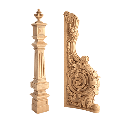
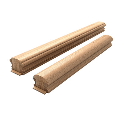
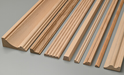
When working with wooden profiles, you can separately check Wooden trim и Wooden moldings and baseboards, if the project allows the use of the relevant profile elements.
If MDF for painting is used, this must be specified precisely as a project scenario. The finish, substrate, and edge will be perceived differently than those of solid wood.
The material cannot be left at the level of "wood look."
Why a slat sample is useful before approval
The more repetitions on the wall, the more even a small difference in cross-section becomes apparent.
A single slat in your hand may seem thin. A hundred identical verticals turn that thickness into visual mass.
Physical Product sample helps to check:
- the actual width;
- the depth;
- shape;
- chamfers;
- surface quality;
- color;
- scale;
- shadow.
It is especially useful to place the sample against the intended background and look at it from a realistic viewing distance.
On a monitor, the spacing between slats is easily perceived abstractly. In a room, repetition is felt physically — through light, shadow, and the scale of the wall.
How to link a DWG to a specific SKU
File reika.dwg says almost nothing six months later.
It is much safer to use clear naming:
STAVROS_[SKU]_DWG
or a design schematic:
RK-01_[SKU].dwg
The same SKU must be in the specification.
The link must work both ways:
drawing → SKU → product
и
product → SKU → drawing.
If a DWG sits separately and is not linked to a real item in any way, similar sections can easily be mixed up over time.
This is especially dangerous when a project uses several profiles of similar size.
Why you should not stretch a slat section in AutoCAD
If the actual product has a section of 30 × 20 mm, the Scale command does not turn it into an existing 40 × 25 mm product.
It creates geometry that may not exist in the catalog.
For a real SKU, you can change:
- position;
- quantity;
- spacing;
- orientation;
- the length of the section if it allows trimming.
But the actual cross-section must remain unchanged.
If the project requires a different width or depth, you need to select a different SKU or switch to a custom product.
This is one of the main rules for working with technical libraries.
How to count the number of individual slats
For a uniform area, it is convenient to first determine the repeating module:
module = slat width + clear gap.
But a universal quantity formula without checking the edge fields can give an incorrect result.
For example:
- area width — 1200 mm;
- slat — 30 mm;
- gap — 20 mm;
- repeating module — 50 mm.
A simple division of 1200 / 50 gives 24 modules.
But this does not automatically mean 24 slats.
You need to determine:
- where the zone begins;
- where it ends;
- whether there are equal margins at the edges;
- whether the width of the last slat is included;
- whether the composition should be centered.
For example, if symmetry is required, the outer margins may need different logic.
Therefore, it is better not to count "how many fit" but to build the layout at actual size and then verify the quantity.
Practical example of calculating a centered zone
Let's imagine a decorative field 1030 mm wide.
A 30 mm wide slat is used, and the design gap is about 20 mm.
Suppose the designer wants to install 20 slats.
Physical width of the slats:
20 × 30 = 600 mm.
remains:
1030 − 600 = 430 mm.
If there are 19 internal gaps between 20 slats and two equal margins are needed at the edges, the distribution can no longer be solved with just the phrase "50 mm spacing."
If the internal gaps are left at 20 mm:
19 × 20 = 380 mm.
For the two edges, the remaining is:
430 − 380 = 50 mm, that is, 25 mm each.
The result is a neat layout:
margin 25 → slat 30 → gap 20 → … → slat 30 → margin 25.
But if the width of the area changes by 40–50 mm due to furniture or opening adjustments, the beautiful balance will disappear.
Therefore, the outer margins must be fixed in the working documentation no less carefully than the repeating step.
How to calculate ready-made slatted panels
With a panel, the logic is different.
Main chain:
zone width → actual panel module → number of full modules → trimming of the edge element.
Here the designer does not distribute each individual slat manually if the rhythm is already set by the manufacturer.
Need to check:
- module width;
- pattern repeat;
- trimming side;
- edge at the opening;
- edge at the corner;
- matching of modules on adjacent walls.
That is why Wall Panels and individual decorative slats should not be mixed in the same calculation.
What to do with niches and short sections
A long wall tolerates a slight pitch correction almost imperceptibly. A short niche does not.
If the section between two fixed boundaries is only 400–600 mm, each module becomes visually significant.
Here it is useful to first check several quantity options:
- fewer slats with a larger gap;
- more slats with a smaller one;
- a symmetrical layout;
- a layout from one edge.
There is no need to mechanically continue the rhythm of the large wall if the short niche starts to look like a random leftover.
The rhythm should support the architecture, not subjugate any surface to itself.
Slats near a staircase or a sloped boundary
If the upper or lower boundary of the zone is slanted, the question of quantity becomes more complicated.
Each slat can have its own length.
In such a case, the total area is not sufficient in the specification.
You need to determine:
- the number of elements;
- the length of each one or of a group of identical lengths;
- cutting rule;
- minimum allowable remainder;
- orientation.
On the drawing, it is useful to number the elements if the differences are significant.
This scenario particularly well illustrates why “slat = line” is too simplified a model.
How to specify slats in the specification
For an individual slat, it is useful to have an entry of approximately the following composition:
| Field | What to specify |
|---|---|
| Code | RK-01 |
| Manufacturer | STAVROS |
| SKU | specific |
| Cross-section | actual |
| Material | wood / MDF |
| Length | actual |
| Step | Project |
| Gap | Project |
| Quantity | pcs. |
| DWG | file name |
| URL | product / category |
Not every field is mandatory for every project, but SKU, cross-section, and quantity cannot be replaced by the general name “decorative slats.”
If the same profile is used in several zones with different spacing, the SKU remains the same, while the zone code and layout differ.
How to design a slatted zone
In addition to the product item, it is useful to have a separate entity — the slatted zone.
For example:
ZONE-RK-01
For it, the following are recorded:
- room;
- width;
- height;
- direction;
- base axis;
- SKU of the slat;
- spacing;
- gap;
- edge margins;
- quantity;
- note on the joints.
This allows using a single product in different compositions.
For example, RK-01 can be installed:
- in the living room with a 60 mm pitch;
- in the lobby with an 80 mm pitch;
- in a partition with a different mounting method.
One product. Different design zones.
What mistakes most often occur in working documentation
The DWG shows a slat without an SKU
The geometry looks real, but it cannot be unambiguously purchased.
What to do: link the file to a specific product code.
Only the pitch is specified
It is unclear whether this is the axial pitch or the clear gap.
What to do: specify the profile width and the gap separately.
The last batten has not been checked
The center of the wall looks good, but the edge ends with a random cut.
What to do: calculate the edge margins before release.
Sockets are shown over the battens schematically
The conflict is discovered on site.
What to do: align the actual dimensions of the electrical accessories with the layout.
The batten is scaled in CAD
The old SKU remains in the specification.
What to do: do not change the actual cross-section of the real product.
The slatted partition is shown only from the front
The actual depth and passage are unknown.
What to do: be sure to add a plan.
The panel is calculated as a set of individual slats
This results in an incorrect number of modules.
What to do: separate the calculation of the slat and the finished panel.
When individual slats may not be the best solution
There are situations where a finished panel is more practical.
For example:
- you need to quickly cover a large surface;
- the designer is satisfied with the rhythm set by the manufacturer;
- there is no need to freely change the pitch;
- installation predictability matters;
- trimming modules is easier than laying out dozens of individual profiles.
Conversely, an individual rail is stronger where a custom rhythm, complex alignment to architectural axes, or a spatial partition is needed.
You should not choose individual rails just because they offer more freedom. Freedom also means more design responsibility.
Checklist before issuing working documentation
Before issuing, check:
- a real SKU is selected;
- the cross-section matches the product;
- DWG is not scaled;
- the actual length is known;
- material is locked;
- layout base is specified;
- spacing specified;
- clearance is clear;
- first batten aligned;
- last batten checked;
- margins on the edges are resolved;
- doors approved;
- hidden doors are checked separately;
- furniture does not conflict;
- skirting and ceiling are resolved in the details;
- sockets and switches are drawn at actual size;
- external and internal corners are detailed;
- there is a plan for the partition;
- quantity is calculated;
- specification matches the DWG.
If even one item still has the phrase "decide on site," that is precisely where deviation from the visualization most often occurs.
How to buy decorative slats after design
The commercial stage only makes sense after the project has answered the technical questions.
First, determine:
- a separate slat or a ready-made panel;
- the material;
- actual cross-section;
- SKU;
- length;
- quantity;
- layout;
- nodes.
After that, you can proceed to ordering.
To make a selection, you can use the section decorative slats for interiors, while for related solutions — a shared one the STAVROS catalog.
If the project is based on solid wood and profile products, it additionally makes sense to check Wooden trim.
For professional work with projects, the section is useful STAVROS for designers and architects, where the project task is considered no longer merely as the purchase of an individual item, but as part of interior furnishing.
The final chain remains short:
SKU → DWG → section → base → spacing → edge margins → nodes → quantity → specification → order.
It is this that turns a slatted wall from decorative hatching into a buildable element of a working project.