Article Contents:
- What a front-on photograph doesn't show about the profile
- Check the width, projection and mounting surfaces
- Treat the finished wall as the common base plane
- Choose the position of the moulding relative to the architrave
- Determine how the frame ends near the door
- Coordinate the lower junction of the skirting and architrave
- Distribute visual emphasis between the bottom, the field and the top of the wall
- Determine the position of the moulding relative to the wall panel
- Check the cornice above the built-in wardrobe
- Review the curtain niche in section
- Coordinate the side junctions to the built-in furniture
- For the concealed door, check the movement separately from the drawing
- Check the section and drawing at the turns
- Supplement the elevation with control sections
- Lock in the specific profile before final approval of the detail
- Build a full-scale sample of the detail
- Link the specification line to the adjacent elements
- Convert the approved details into cutting and ordering

On the flat layout, the molding meets the door casing without visible issues. After installation, it turns out that the relief protrudes beyond the door frame, and its end face is exposed on the passage side. At the bottom, a similar situation arises with the baseboard; at the top, with the cornice, which ended up in front of the opening cabinet door.
Architectural stucco for interiors requires checking such junctions before purchase. The style and width of the face help choose the wall pattern, but they do not determine how the parts will meet in three dimensions. This requires the actual cross-section, the mounting plane, and the position of adjacent surfaces.
A successful solution does not necessarily align all the decor in a single plane. The casing may protrude in front of the frames, the panel may sit deeper than the profile, and the cornice may form a noticeable wall termination. What matters is that every offset is planned and has a neat structural solution.
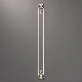
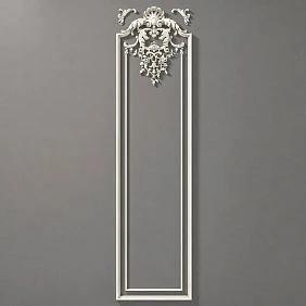
What a frontal photo does not show about a profile
A photograph conveys the overall contour and character of the ornament well. But from it, it is difficult to determine where the back surface is, which area actually adjoins the wall, and how far the outermost point of the relief protrudes. Against a light background, shallow and voluminous profiles can appear similar.
Therefore, during the initial review of architectural polyurethane stucco it is worth separating two tasks. The image helps shortlist options by character, while the cross-section helps verify their placement. An attractive product card does not yet confirm compatibility with a specific casing or wall panel.
Be especially attentive to details that end in a visible place. In a frontal image, the end face almost disappears, but when viewed from the hallway it becomes a noticeable surface. For the cornice, by contrast, the lower angle matters, since that is how a person usually sees it in the room.
If the selected product lacks sufficient data, clarify the geometry before the final layout. Adjusting the project to an approximately guessed depth is inconvenient: changing one profile can affect the door assembly, the furniture, and the distance to the adjacent frame.




Check the width, projection, and mounting surfaces
To compare profiles, you need parameters with clear measurement directions. The letters in the product cards are explained by the specific drawing: the same designation in different categories should not automatically be understood the same way.
| Parameter | What does it describe | What it is for |
|---|---|---|
| Width on the wall | The strip occupied by the installed profile | Checking the frame and clearance |
| Projection from the base | Position of the front points relative to the mounting surface | Comparison with the architrave and panel |
| Cornice overhang | Its horizontal extent in the installed position | Checking the cabinet, ceiling and niche |
| Mounting surfaces | Areas of contact with the base | Checking the fit and fastening method |
The mounting plane is not a separate linear dimension, but a measurement datum. With a complex cornice, it is also important to distinguish the height along the wall from the projection along the ceiling. The depth of the relief itself describes variations in the pattern and is not always equal to the full thickness of the product.
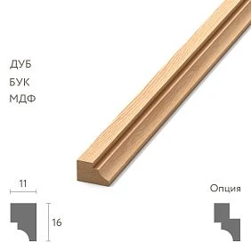
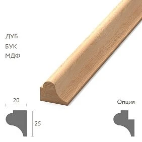
Conventional mouldings 45 mm wide with projections of 11 and 24 mm will occupy the same strip of wall. But next to an architrave and in side light they will be perceived differently. This is a comparison example, not the characteristics of specific SKUs. For the assembly, both directions are checked, even if the width has already been agreed.
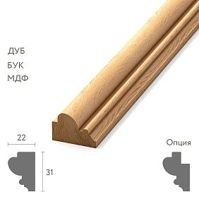
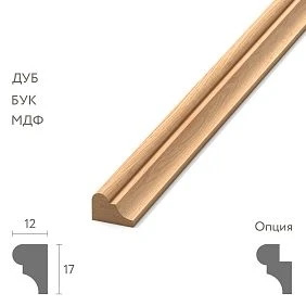
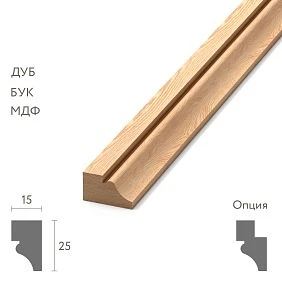
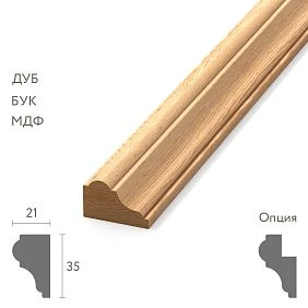
Our factory also produces:
Take the finished wall as the common base plane
To compare products, a single depth reference is needed. The surface of the finished wall can be taken as the conventional zero. Then mark where the mounting surface and the outermost face points of each part are located. This reveals the variations that are lost when comparing individual product cards.
Let us consider a conventional diagram. The installed moulding projects 18 mm from the surface to which it is attached; the outer point of the architrave is 25 mm from the wall. The panel creates a finished surface at a distance of 12 mm from the same zero.
| Part and installation location | Base position | Position of the frontmost point |
|---|---|---|
| Molding directly on the wall | 0 мм | +18 mm |
| Casing in the adopted assembly | By its design | +25 mm |
| Same molding on the panel | +12 mm | +30 mm |
On the wall, the molding is 7 mm behind the frontmost point of the casing, while on the panel it is already 5 mm in front. Its own cross-section has not changed; the base has changed.
The calculation uses the positions of the finished surfaces, taking into account the specified installation layers. Comparing the maximum protrusions is the first step: at the joint itself, the local edge shape of both parts is also checked.
Get Consultation
Select the molding position relative to the casing
Near the doorway, various depth relationships are possible. None of them should be declared mandatory for all interiors. What matters is the chosen role of the portal and how the termination of the adjoining line is designed.
| Ratio | Visual Result | What to check in the joint |
|---|---|---|
| The molding is set deeper | The casing can take the line as a more protruding boundary | Whether its edge covers the required section of the end face |
| The face points are close in depth | The transition looks calm with precise joining | The shape of the edges and the alignment of surfaces at the joint |
| The molding protrudes further | The termination becomes an independent accent | Visible end, return, or separate termination |
At the same time, the maximum width of the casing does not always describe its outer edge. The cross-section may rise toward the middle and become thinner where it meets the molding. Therefore, comparing the two largest numbers is not enough.
Choosing Moldings made of polyurethane, the cross-section is applied to a specific point of the door trim. If the parts should not touch, a clearance is set. Such a solution is often easier to approve than trying to join profiles that differ in pattern and depth without a designated transition.
Determine how the frame ends near the door
A closed frame can stop before the casing and retain an independent outline. An open horizontal line requires a separate end solution: a prepared end, a return to the wall, or a compatible decorative termination. These options take up different amounts of space and cast different shadows.
A return turns the cross-section toward the base with a short matching fragment. Its geometry is determined by the actual projection of the installed profile. The length of such a fragment is not automatically equal to the face width of the molding; the joint must be constructed and checked before cutting.
If the pattern continues through the portal, the transition on the jambs and outer surfaces is agreed first. A single line on the elevation drawing is not enough to resolve all the turns. Sometimes it is better to preserve only the visual horizontal on both sides of the opening, finishing each part separately.
On a very narrow wall section, the frame can be omitted. Trying to extend the molding "as far as possible" often leaves a random piece of the field and an awkward end. The entire area is checked together with the casing, the switch, and nearby furniture. The chosen end point is marked on the drawing so that it is not determined again during installation.
Coordinate the lower joint of the baseboard and casing
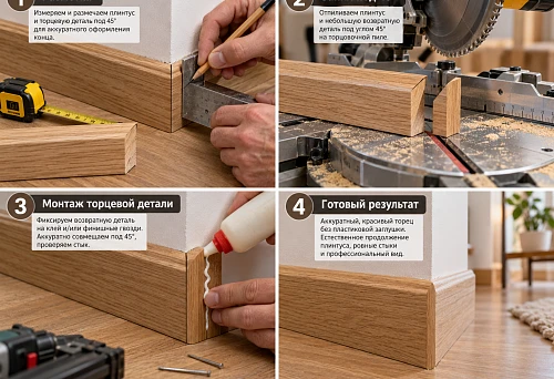
At the floor, the horizontal baseboard meets the vertical door trim. Here, the cross-sections of both products and the position of their edges must be known. The height of the baseboard alone does not indicate how neatly it will fit against the casing.
If the skirting board protrudes beyond the receiving edge, part of its end face will remain exposed. This can be treated as an intended termination or resolved with a different transition detail. One option is a plinth block at the base of the architrave, with dimensions coordinated with both profiles.
The block is not chosen by height alone. Its projection, width, position relative to the architrave, and how the skirting board meets it are all checked. It becomes a visible part of the portal, so it must suit the door's composition. In a calm interior, a different termination method may be more appropriate than an additional accent.
The lower junction should be resolved before finalizing the frames above it. Otherwise, the face plane of the portal will change after the entire wall is coordinated. Do not assume that sealant or painting will fix any discrepancy: joint treatment materials do not create missing geometry. A trial fit gives a clear answer before ordering a set for the room.
Distribute the expressiveness between the bottom, the field, and the top of the wall
The skirting board marks the lower boundary, the moulding divides the wall field, and the cornice completes it at the top. These roles do not require the same width, projection, or ornament. On the contrary, fully identical expressiveness of all lines can deprive the composition of its main accent.
First, determine which level should be the most noticeable. On a wall with a prominent cornice, the frames can remain calm. With an expressive central panel, the top and bottom can work as more restrained boundaries. The decision is checked in the overall view and under side lighting.
Between the skirting board and the lower frame, assess the clear field; between the upper frame and the cornice, assess the remaining wall plane. The dimensions of these sections are tied to the actual edges of the products. Replacing a thin nominal profile with a wider one will reduce the field even if its axis has not shifted.
Depth also affects the shadow. Therefore Polyurethane trim consider it in combination with the other elements. However, profiles separated by a free field and not forming a joint are not required to be in the same face plane. Here, the visual relationship is checked, and at the point of direct abutment, structural compatibility is checked as well.
Determine the position of the moulding relative to the wall panel
Molding can sit on top of the panel, be positioned next to it, or cover its edge. With the same frontal pattern, different cross-sections result. Therefore, the drawing first shows the panel itself, its base and the finished face surface, then adds the profile.
When installed on top of the panel, the molding's projection is added to the distance from the wall to its face side. If the profile is positioned alongside, it is not the sum but the position of two independent surfaces that is compared. For edge framing, additionally check what covers the panel end and which parts of the molding have support.
A profile with a flat back is not always suitable for bridging the step between the wall and the panel. In the drawing it may cover the boundary, but in reality it may only contact along a narrow strip. The installation method for such a junction is agreed based on the actual geometry and fastening requirements, rather than filling the missing support with an arbitrary layer of adhesive.
If the panel receives additional finishing, take the final surface into account. It is especially important not to mix the dimensions of the unfinished base and the finished part. The transition should be checked in the state in which it will be visible in the interior, including edge treatment and the selected profile finish.
Check the cornice above the built-in wardrobe
A cornice has a height along the wall and a projection toward the room. Above a wardrobe, both parameters affect the solution: the lower part may come close to the facade, while the projecting part may end up in the path of an opening door. A frontal elevation does not show this conflict fully.
In the vertical section, combine the wall, ceiling, top of the carcass, facade and cornice. Then check the intended door movement and the feasibility of assembling the furniture. The installation gap is set according to the specific wardrobe design, not by using an arbitrary identical value for all products.
Choose the cornice route in advance. It may end before the furniture, return to the wall, run above a fixed frieze, or continue into a separate furniture composition. If the cornice is fastened to different bases, their connection and the sequence of work are shown in the detail.
Do not rotate the real profile in the model just so that it fits above the wardrobe. Changing its position changes its visible height, projection and contact surfaces. The permissible orientation is determined by the product geometry and the adopted installation technology. In case of a conflict, revise the cornice, the furniture top and the available space together, not just the decorative line.
View the curtain recess in section
The cornice near the window interacts with the niche, the curtain track, the fabric and sometimes the lighting. A section is needed that shows not only the wall and ceiling but also the position of all these elements. A beautiful frontal outline does not show whether there will be room for the curtain to move.
The path of the fabric, its volume when gathered and the distance to protruding decorative parts are checked. The width of the niche is determined by the chosen curtain system and the project conditions. A universal offset from the wall does not replace the actual dimensions of the tracks, the windowsill and other adjacent parts.
Access to the fasteners and serviceable elements is also provided for. If the assembly includes lighting, the placement of the equipment, the light and the required installation conditions are considered separately. The decorative profile must not accidentally cover the required access area.
A cornice for a wall and a profile designed for finishing a niche may have different mounting surfaces. Therefore, the selected part is checked in the planned scheme, without assuming that any similar profile can be fixed on only one side. On a test fragment, both the technical placement and the appearance of the niche from normal room viewpoints are assessed.
Coordinate the side junctions with built-in furniture
In addition to the upper assembly, a built-in wardrobe or bookcase has a side boundary with the wall. The frame may end before the furniture, meet a fixed side panel or visually continue onto the facade. Each option corresponds to its own position of the front surfaces.
If the wall profile and the furniture decor are to be perceived as a single line, their sections and the actual projection from the common base are compared. Matching height on the elevation drawing does not yet mean matching depth. The transition is especially noticeable when light is directed along the wall.
The fixed side panel and the opening door are considered separately. Continuing the pattern across a moving joint does not mean it can be covered by a solid strip. The opening conditions and the clearances provided by the design must be maintained.
If nearby there is molded decoration made of polyurethane, its extreme points are taken into account. The scroll may protrude beyond the main frame and intersect with the handle or the path of the facade. The check is carried out using the full outline and volume. The combined wall and furniture scheme is approved before the dimensions of the fixed side panel or facades go into production.
For a concealed door, check the movement separately from the pattern
On a concealed door, the face of the leaf in the closed position can continue the wall. This makes it possible to run a moulding composition across it. But the geometry of the closed view does not describe the movement of the leaf: a projecting profile may come close to the adjacent wall or the matching decor when opening.
The plan and section show the frame, the leaf, the opening direction and the actual moulding cross-section. The limitations of the specific door system are checked, including whether additional decor is permissible. There is no universal gap that suits all concealed hinges and profiles.
The line is divided along the boundaries of the moving and fixed parts. The edges of the moulding receive the specified treatment, and the joint remains functional after painting. The technique of solidly filling the seam from a fixed wall frame must not be transferred to the outline of an opening door.
It is useful to check a full-size fragment with the actual projection of the decor. If the profile has to be trimmed excessively for opening, return to the choice of cross-section or the position of the frame. The result must preserve both the composition of the closed wall and the normal use of the door. One attractive visualisation is not enough for such a detail.
Check the cross-section and the pattern at the turns
At the corner, two tasks matter: joining the spatial geometry of the profiles and preserving the character of the pattern. With a smooth moulding, the main check concerns the continuation of the cross-section. With an ornamental one, the position of the motifs and the place where they meet are added.
Choosing Carved polyurethane molding, clarify the pattern repeat and the possible layout on the sides of the composition. A precise corner cut does not guarantee that two cut sheets will not meet at the joint. The matching of the motif must be checked separately.
For the internal and external corner, use the actual position of the mounting planes. If the cornice is installed between the wall and the ceiling, its cross-section cannot be checked as if it were a flat wall-mounted strip. The spatial form of the joint depends on the orientation.
Before cutting the whole batch, assemble a representative corner and the nearest end, if there is one. Check the continuity of the face tracks, the absence of an accidental step and the side view. A small trial detail helps to detect an error that would then be repeated at every turn. Differing angles or bases need their own solutions, not automatic copying of the first successful joint.
Supplement the elevation with control sections
The elevation shows doors, architraves, skirting, frames, cornice and furniture. It indicates axes, intervals and height relationships. Then, at the points where parts directly interact, sections are made: through the moulding and architrave, the panel and profile, the cabinet and cornice, the curtain recess.
One standard section can serve repeated identical assemblies. But it does not confirm solutions with a different panel thickness, a different architrave edge or a different opening direction. These changes must be visible in the documentation.
The section shows the finished base, mounting surfaces and the actual outline of the products. Dimensions are set from a common datum, marking critical clearances and projections. A simplified rectangle instead of a complex profile is acceptable only where it is sufficient for the task being checked. A true cross-section is required for edge junctions.
Materials from catalogs, drawings, and models of STAVROS are checked against the selected article and finish. A DWG file is useful for building an assembly if the scale, units and orientation have been verified. The mere presence of a file does not confirm that the correct version of the part has been inserted into the project or that all installation surfaces are shown correctly.
Confirm the specific profile before final approval of the assembly
A preliminary composition can be built with a simplified section. But the final junction must be based on a product with known parameters. After selecting the article, check the dimensions, material, supply length and shape of the mounting side, then refine the design geometry.
For example, in the product page polyurethane moulding MLDPU-001 a cross-section of 10 × 6 mm and a length of 2600 mm are specified. These data provide a concrete basis for the drawing and cutting. They do not mean that such a profile is suitable for any architrave: suitability is determined by the assembled junction.
If the visualization requires a wider or deeper profile, you cannot simply enlarge this model and keep the same item code in the specification. Scaling changes the physical product on screen, which may not exist in the selected supply. You need to select a different product or separately agree on development.
Replacement during procurement is handled in the same way. A similar name and a similar photo are not sufficient. The new item code is re-checked against the parameters that the junctions depend on, and the documents are updated as a single agreed version.
Assemble a full-scale sample of the junction
For checking depth, a combination of parts is more useful than an isolated fragment of molding. Place a casing or its exact mock-up, a section of the panel, and a base of the required thickness next to each other. The sample should reproduce the planes that were compared on the section.
If the panel is not yet ready, its position can be reproduced on a mock-up. It is important to preserve the final depth rather than attach all the parts to a single flat board and get an artificial match. For moving elements, the design trajectory is checked separately.
Product samples are selected by composition and task. A short segment shows the cross-section, but it does not necessarily allow you to assemble a corner or a return. The availability of a specific product and the amount of material for a trial junction are confirmed in advance.
After checking the geometry, the agreed paint finish is applied. The same color can unite the parts, but the shadow from the step will remain, and different gloss may sometimes make it more noticeable. The inspection is carried out from the front and the side, under normal and raking light. The approved sample is kept together with the product designations and the junction version so that the contractor can reproduce exactly the combination that was checked.
Link the specification line to the adjacent elements
A simple entry such as “white molding” is not enough for purchasing architectural trim. The specification must identify the product and link it to the place of application. Then a replacement will not go unnoticed by the specialist who checked the junctions.
| Field | What is recorded |
|---|---|
| Project code | Conventional designation of the position on drawings |
| Manufacturer and item code | Full manufacturer name and exact product code |
| Type and material | Molding, cornice, or baseboard; material of the selected item |
| Dimensions | Profile, height, projection, and other parameters per the drawing |
| commercial length | Length of the supplied plank for cutting calculations |
| Junction | Adjacent casing, panel, or furniture and node number |
| Documentation | Link to the verified profile and current version |
| Finish and sample | Approved coating and reference designation |
| Quantity | Purchase quantity of planks or parts in the specified units |
| Product card | Clean link to the selected product |
The installed position relative to the wall is stored in the node, since it also depends on the substrate. The profile's own thickness in the product line does not replace this information.
If one item is used both on the wall and on top of the panel, the layout must distinguish between these zones. The article number can remain the same, while the checked junctions differ. For project coordination, you can use STAVROS materials for designers and architects, preserving the link between the catalog product and the specific construction.
Convert the approved nodes into cutting and ordering
After choosing the geometry, determine the lengths of the parts: straight sections, frame sides, turns and returns. For ornamental mouldings, take the position of the pattern into account. Only then are these parts laid out across the product strips with the allowances for processing.
Suppose the net total length is 38.6 m, and the selected strips are 2.6 m long. Fifteen strips give 39 m, but this is only a check of the total length. It does not prove that all the required continuous sections can be accommodated within these fifteen strips. The cutting map provides the answer.
Offcuts are assessed by their suitability for specific parts, and the reserve by the accepted work scheme. A short fragment will not replace a long continuous section; a suitable length does not guarantee a matching repeat. Corner and end elements are counted as separate items if the system provides for them.
Once these data are agreed, you can Buy polyurethane wall moldings and the remaining elements according to the verified set. In the order, check the article numbers, finishes, quantities and delivery terms. The installer is given the current nodes: where the face plane runs, how the profile ends and which part it must join to. These are the decisions that preserve the architectural logic of the wall after installation.