Article Contents:
- Why the cornice and modular ceiling cannot be designed independently
- For the ceiling grid, not only the size of the cornice is critical, but also its projection
- A photograph of the cornice does not show its impact on the ceiling
- What initial data is needed before calculating a wholesale batch
- Finished dimensions of the room
- Suspended ceiling plan
- Module size of the specific system
- Position of the load-bearing grid and visible seams
- Ceiling marking
- Precise cornice
- Height and projection
- Perimeter ceiling solution
- Position control
- Zone control
- Step 1. Typify the rooms
- Step 2. Fix the KZ
- Step 3. Obtain the ceiling module
- Step 4. Develop the units
- Step 5. Check the corners and boxes
- Step 6. Assembling the control fragment
- Step 7. Approving revisions
- Step 8. Only now do we calculate the wholesale batch
- 1. Measuring the ceiling grid from the wall and not accounting for the cornice projection
- 2. Choosing a KZ based only on a photo
- 3. Looking only at the height
- 4. Approving the grid before choosing the cornice
- 5. Approving the cornice and not showing it to the ceiling installers
- 6. Allowing accidentally narrow edge modules
- 7. Treating all rooms as identical
- 8. Transferring the study's junction detail to the hallway
- 9. Not accounting for columns and bulkheads
- 10. Do not make a cut
- 11. Do not lock the KZ article number
- 12. Changing KZ without checking the grid
- 13. Changing the ceiling system without checking the cornice
- 14. Mixing materials in one line
- 15. Ordering the entire linear footage before approving the units
- 16. Marking the cornice by floor only
- 17. Treating the decorative KZ as part of the load-bearing ceiling system

A wooden ceiling cornice and a modular suspended ceiling are often designed by different specialists. The architect chooses the profile of the upper wall line, the ceiling specialist lays out the grid, and the specifier later receives two already approved solutions and must bring them together in a single room. It is at this moment that it becomes clear that the visual boundary of the ceiling is no longer where it was assumed to be in the first plan.
If the suspended ceiling is laid out from the finished wall, and a wooden cornice with a noticeable projection into the room then appears along the perimeter, the visible width of the outermost row of modules decreases. A full outermost element turns into a narrow strip. In a single office, this looks like a local failure. On a project with sixty identical rooms, the mistake is repeated dozens of times and becomes systemic.
Therefore, wholesale sales of wooden cornices for projects with modular suspended ceilings should begin not with the total square footage, but with coordinating the geometry of the two systems.
Need to know:
-
finished dimensions of the room;
-
the actual modular ceiling grid;
-
size and type of ceiling module;
-
position of the perimeter elements of the ceiling system;
-
selected wooden cornice;
-
its height and projection;
-
internal and external corners;
-
columns, niches, and bulkheads;
-
ceiling level changes;
-
typical rooms;
-
the approved relative position of the cornice and the ceiling.
Only after that does it make sense to move on to the linear footage, commercial length, number of whole strips, cutting plan, reserve, and wholesale supply.
Main principle:
first the coordination of the cornice and the ceiling grid, then the purchase of the cornice.
This is not a guide to suspended ceiling installation. The purpose of the article is to show what data must be coordinated between the architecture, the ceiling system, and the procurement of wooden trim before launching a large batch.
Why the cornice and the modular ceiling cannot be designed independently
Let us imagine an ordinary office.
A wooden ceiling cornice is provided along the perimeter of the wall. Inside — a suspended ceiling with a regular modular grid.
If the ceiling specialist first takes the finished walls and lays out the modules relative to them, the visible edge of the ceiling is calculated from the wall.
After that, the architect adds a cornice that protrudes into the room.
The physical ceiling may remain in its original place. But the visual boundary changes.
Part of the outermost module ends up hidden under the cornice or behind its inner edge. As a result, a module that looked normal on the plan can turn into a narrow strip in the finished interior.
The problem is especially noticeable where the ceiling grid is open and the seams are visible.
In the center of the room, the modules remain regular. At the edges, a visually random border appears.
On a serial project, this defect is repeated.
Suppose the same office occurs sixty times. One incorrectly calculated junction produces sixty identical unsuccessful edge strips.
Therefore, the right question is not:
What should be designed first — the ceiling or the cornice?
More correctly:
What visible ceiling boundary will result after installing the selected cornice, and how should the modular grid work relative to it?
It is precisely this boundary that must be agreed upon before wooden cornice it goes into mass ordering.




For a ceiling grid, not only the size of the cornice is critical, but its projection
When choosing a ceiling cornice, height is often discussed first.
A tall profile is more noticeable on the wall. A low one looks calmer. But for a modular ceiling, another dimension is especially important — how far the profile protrudes from the wall into the room.
It is precisely this projection that changes the visible plane of the ceiling perimeter.
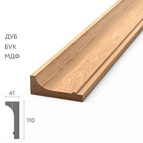
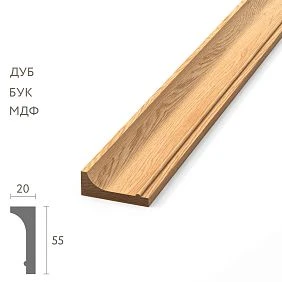
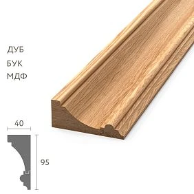
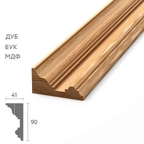
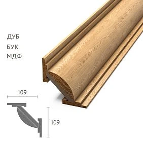
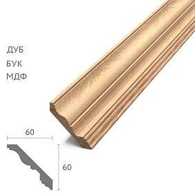
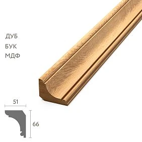
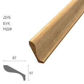
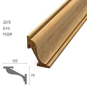
For example, KZ-015 has a cross-section of 61×87 mm, and for ceiling coordination the 87 mm projection is critical.
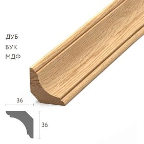
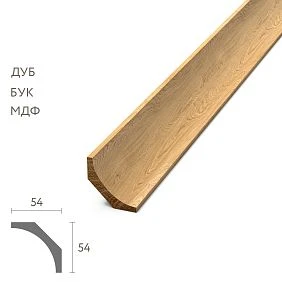
KZ-016 has a cross-section of 54×54 mm.
The difference in projection between these profiles is 33 mm.
For a standard interior description, this is a difference in proportions.
For a modular grid, it is already a different position of the inner boundary along the entire perimeter.
If the outermost ceiling element was calculated as 180 mm of visible width before installing the cornice, a deeper profile can reduce this strip by a few more centimeters. What initially looked acceptable becomes too narrow after adding the cornice.
Therefore, in the working table you cannot write only:
KZ-015.
You need to store at minimum:
item code → cross-section → actual projection → material → room → ceiling node type.
An item code without geometry is weak for interdisciplinary coordination.
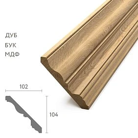
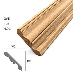
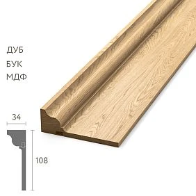
Our factory also produces:
A photograph of the cornice does not show its effect on the ceiling
Two profiles in an interior photograph may appear similar.
One is slightly deeper, the other a bit more compact.
In a separate image, this difference is not always noticeable.
But a modular ceiling grid reads the geometry much more strictly.
If the offset differs by 20–30 mm, this difference repeats:
-
along the long wall;
-
along the short wall;
-
at every inner corner;
-
around the column;
-
near the bulkheads;
-
in every identical office.
Therefore, when purchasing profile in bulk, you cannot choose the final KZ based only on a photograph or decorative styling.
First, the architecture approves the suitable profile.
Then its actual cross-section is passed to the ceiling designer.
After that, the grid is checked against the inner edge of the approved cornice, not against an abstract wall.
This does not mean that the ceiling should dictate the choice of decorative profile.
But the decorative profile also should not exist in the project separately from the actual ceiling perimeter.
Get Consultation
What initial data is needed before calculating a wholesale batch
Before moving on to the quantity of cornice, the kit assembler needs a set of initial data.
Finished dimensions of the room
Not rough masonry and not dimensions between frames.
The cornice and ceiling system operate relative to the finished surfaces.
If, after plastering, the room has become 20 mm narrower, this also matters for the edge modules.
Suspended ceiling plan
It should show the actual grid, not just a schematic hatching.
Module size of the specific system
The common example of 600×600 mm must not be turned into a universal rule.
A different size, rectangular panels, or custom modularity may be used on site.
Position of the load-bearing grid and visible joints
For architectural coordination, it is important to understand where the boundaries of the elements visually run.
Ceiling elevation
It is needed for cutting and checking the vertical alignment.
Exact cornice
An article number is needed, not the phrase "medium-sized wooden cornice".
Height and projection
Both parameters must be confirmed for the specific profile.
Perimeter ceiling solution
The wooden cornice and the standard wall-mounted ceiling system element must not accidentally come into conflict.
The exact method of their relative positioning is determined by the design.
Why room dimensions must be finished dimensions
An unfinished room may differ from the finished one.
The position of the walls changes after:
-
plaster;
-
cladding;
-
wall panels;
-
removing the corners;
-
installing decorative layers.
If the ceiling grid is calculated based on the rough dimension, while the cornice is ordered based on the finished wall, the two systems begin to rely on different bases.
On an ordinary smooth ceiling, the difference may remain unnoticeable.
In a regular modular grid, it shows up in the edge elements.
Let's imagine a design width of 4800 mm.
After finishing, the finished width became 4778 mm.
The difference is 22 mm.
If the grid was centered on the old dimension, the two edges will already shift by approximately half of this deviation, and then the cornice projection additionally affects them.
Therefore, before final approval of the standard unit, it is useful to verify the actual dimensions of at least the reference rooms.
For dozens of identical rooms, it is not necessary to measure each one before the first discussion. But the standard system must be tested on a real site before mass ordering.
The ceiling module is a parameter of a specific project, not a universal 600×600
In discussions about suspended ceilings, the figure 600×600 mm often appears automatically.
For the approval methodology, this is only an example.
A real site may use:
-
a different square module;
-
a rectangular module;
-
a linear ceiling system;
-
acoustic panels;
-
cassette system with a different geometry;
-
individual grid.
Therefore, the cornice configurator should not design the ceiling itself.
Its task is to obtain from the ceiling section:
-
actual module;
-
layout;
-
position of the end elements;
-
perimeter rules.
After this, it adds the cornice offset to the coordination.
This is how the interdisciplinary boundary becomes clear.
The main problem arises in the end module
In the center of the room, a regular grid is usually predictable.
Difficulties arise along the perimeter.
The width of the edge module depends on:
-
the overall size of the room;
-
the position of the grid;
-
the chosen centering principle;
-
columns and niches;
-
ducts;
-
the inner edge of the cornice.
That is why the edge element cannot be assessed based on the general plan alone.
For example, before choosing a curtain rod, the remaining strip along the wall looks like 210 mm.
After installing a profile with an 87 mm offset, a significantly smaller part remains visually open.
If the architecture was meant to achieve a calm edge, such a result may be unacceptable.
Conversely, a compact profile will reduce the impact on the end module.
But this does not lead to the conclusion:
let's choose the smallest curtain rod so the ceiling installers have it easy.
The curtain rod remains an architectural element.
The task of coordination is not to subordinate the architecture to the ceiling, but to find a compatible solution.
Why random narrow cuts spoil the entire perimeter
A narrow strip along one wall looks like a local mistake.
If it runs along all four sides of the room, the ceiling visually gains an additional frame.
Moreover, this frame can be of different widths:
-
along the long wall it is one;
-
along the short wall it is another;
-
near the column it is a third.
Instead of a regular modular system, there is a feeling that the ceiling was simply “extended” to the walls with leftovers.
In a hotel or office property, the problem is amplified by repetition.
Each room becomes proof of the same mistake.
Therefore, even at the stage of the typical unit, it is useful to ask:
After the cornice appears, does the end module look meaningful or like a random offcut?
This is a visual question, but its resolution directly affects procurement: if the cornice changes, the ceiling perimeter is recalculated; if the grid changes, the approved cornice must be rechecked.
What to design first: the cornice or the ceiling
There is no strict universal order.
It is incorrect to state:
always the ceiling first.
It is equally incorrect:
always the cornice first.
On a strong project, these decisions develop in parallel.
The architect determines:
-
the scale of the upper line;
-
stylistics;
-
the required height;
-
profile depth;
-
material;
-
finishing.
The ceiling designer determines:
-
system;
-
module;
-
the load-bearing structure;
-
layout;
-
edge margins;
-
perimeter elements.
After this, the decisions are superimposed on each other.
If there is a conflict, a deliberate adjustment is sought.
Sometimes it is reasonable to shift the grid slightly.
Sometimes it is better to choose a different profile.
Sometimes the position of the edge seam is changed.
Sometimes a specific room gets its own assembly.
The main thing is to make the decision before wholesale purchasing.
The curtain rod offset should be a separate specification field
For a regular product purchase, the SKU may be sufficient.
For coordination with the ceiling — no.
Convenient working table:
| Room | Article | Height | Projection | Material | Ceiling assembly |
|---|---|---|---|---|---|
| O-01 | KZ-015 | 61 мм | 87 мм | Per specification | KP-01 |
| O-02 | KZ-016 | 54 мм | 54 мм | Per specification | KP-02 |
Such a table immediately shows why two similar rooms cannot automatically be considered identical.
It is especially important not to transfer the geometry of one product code to another.
If the project replaced KZ-015 with KZ-016, you cannot keep the previous projection just because "it is also a wooden cornice."
Each profile has its own cross-section.
A comparison of KZ-015 and KZ-016 shows the purpose of coordination
KZ-015 has a cross-section of 61×87 mm.
For ceiling coordination, 87 mm is a critical projection.
KZ-016 has a cross-section of 54×54 mm.
Difference in projection:
87 − 54 = 33 mm.
On a short sample, 33 mm may seem small.
But along the entire ceiling perimeter, this is already a different inner line.
If the ceiling grid is designed for one profile, replacing it with another can:
-
enlarge the outermost visible module;
-
reduce it;
-
change the symmetry;
-
shift the visual seams relative to the walls.
Therefore, replacing the KZ after the ceiling grid has been approved must always undergo re-verification.
This does not mean that KZ-015 is worse or better than KZ-016.
They solve different architectural tasks.
The comparison shows only one thing: the cornice profile is part of the room's ceiling geometry.
An architectural cornice cannot be chosen solely for the convenience of the ceiling tile
A ceiling system has technical requirements.
But a wooden cornice is not chosen based on those alone.
It forms:
-
the scale of the upper line;
-
wall proportion;
-
relationship with doors;
-
relationship with the baseboard;
-
character of the interior.
If a large profile is required, it cannot be automatically reduced just so that the outermost ceiling module becomes wider.
First, grid coordination options are checked.
If a solution is possible, the architectural profile is retained.
If not, the architect makes a conscious decision to replace it.
This is fundamentally different from a situation where the supply department independently chooses a “smaller cornice.”
But the ceiling system cannot be ignored either
The opposite extreme is to commit to a deep wooden cornice without showing it to the ceiling specialists.
Such a profile may visually intrude into the already calculated zone of the edge modules.
On the plan, the cornice looks beautiful.
The ceiling grid is beautiful too.
Together, they create a conflict.
That is exactly why, before Buy wooden crown, it is useful for the specifier to request not only the wall elevation but also the current ceiling plan.
For a large project, this is especially important: the cost of an error is multiplied by the number of rooms.
The centering of the grid should be checked relative to the visible boundary
In a regular ceiling, the goal is often to achieve a meaningful distribution of the edge elements.
How exactly this is done depends on the specific ceiling system and project.
The article should not replace the ceiling designer with a universal formula.
But there is a principle that is useful for cornice specification:
the visible boundary of the ceiling after cornice installation may not be on the finished wall, but along the inner edge of the profile.
Consequently, it is this line that must be communicated to the ceiling designer.
On the plan, it is convenient to show it as a separate control line.
This way, the ceiling is calculated not in an abstract empty room, but together with the real upper architectural frame.
Why a universal formula is dangerous here
Different suspended ceiling systems have their own rules:
-
the load-bearing structure;
-
restrictions on cutting;
-
wall-mounted elements;
-
mounting;
-
access to engineering systems;
-
manufacturer's requirements.
Therefore, you cannot write:
the end module must be at least X.
Without reference to a specific system, this would be an invented universal rule.
The right material teaches something else:
-
determine the actual cornice;
-
get its projection;
-
pass this projection to the ceiling section;
-
check the end module;
-
approve the assembly;
-
only then send the cornice to the wholesale order.
A typical room is first checked separately
On a serial project, it is convenient to enter the room code.
For example:
O-01 — typical office.
For it, the following are recorded:
-
finished width;
-
finish length;
-
ceiling height;
-
cornice item number;
-
removal;
-
type of ceiling system;
-
module;
-
approved layout.
After coordination, the assembly is issued:
KP-01 — cornice + ceiling grid.
The node must make it clear:
-
where the wall is located;
-
where the inner edge of the cornice is;
-
where the visible ceiling begins;
-
how the end module runs;
-
where the wall-mounted part of the ceiling system is located.
Such a node becomes repeatable.
If a site has eighty identical offices, there is no need to make the architectural decision anew in each one.
But before replicating, it is necessary to make sure that the rooms are truly identical.
Mirrored rooms do not always require a new node
If the room is fully mirrored, and the ceiling grid is symmetrical and contains no local bulkheads or niches, KP-01 can work in both the left and right versions.
But this needs to be verified.
Differences can be created by:
-
column;
-
an engineering bulkhead;
-
additional equipment;
-
a niche;
-
a change to the door portal;
-
a local ceiling insert.
If the geometry changes, a new type appears:
KP-02.
You shouldn't artificially create dozens of nodes. But you also can't transfer a standard node to a place where its base has already changed.
A long corridor requires different logic than an office
In an office, the ceiling grid works within a compact geometry.
In a corridor, it stretches over a greater length.
Along the two long walls, the cornice forms a continuous inner frame.
Here it is especially clear how symmetrical the grid is relative to the left and right sides.
Even a slight systematic offset can create a long narrow strip along one wall and a wider one along the other.
The transverse walls matter too.
They are what determine the residual module along the length of the corridor.
That is why the corridor gets its own ceiling-and-cornice assembly, even if the same KZ is used as in the offices.
An elevator lobby cannot be automatically copied from a corridor
The elevator hall can:
-
have a different size;
-
a different ceiling module;
-
a larger cornice;
-
different columns;
-
a different ceiling composition.
If KZ-015 is used in the corridor and KZ-016 or another profile is used in the hall, the geometry of the end modules changes.
Even with a single KZ, the ceiling grid of the hall must be checked separately if the room geometry is different.
Therefore, it is useful to store the following in the master table:
| Room Type | Crown Molding | Ceiling system | Node |
|---|---|---|---|
| Office | KZ-015 | P-01 | KP-01 |
| Corridor | KZ-015 | P-02 | KP-02 |
| Hall | KZ-016 | P-03 | KP-03 |
This is much more reliable than a string:
cornice KZ-015 — the entire fourth floor.
An open transition between the corridor and the hall requires a separate solution
If the corridor ends with a door, the boundary is clear.
If it flows freely into the hall, an architectural question arises:
-
does the corridor cornice end;
-
does it continue;
-
does another profile begin;
-
where does the ceiling grid change;
-
is it necessary to align the seams of the two systems.
If these issues are not resolved on the plan and section, installation teams begin making decisions on site.
As a result, a single profile may break off accidentally, and the ceiling grid may change its rhythm without an architectural reason.
For a serial project, the transition is better designed as a standalone detail.
A single cornice SKU can be used in different rooms, but the ceiling is still checked separately
KZ unification is useful.
It:
-
reduces the number of SKUs;
-
simplifies ordering;
-
simplifies reordering;
-
preserves the architectural language.
But an identical cornice does not make the spaces identical.
An office 3600 mm wide and a corridor 2400 mm wide have different residual ceiling grid margins.
Therefore, one KZ can participate in several nodes:
KZ-015 → KP-01, KP-02, KP-04.
Item one.
Ceiling-perimeter solutions differ.
Multiple cornices require multiple perimeter nodes
If the project uses KZ-015 and KZ-016, at least two types of offset already exist.
Consequently, it is impossible to create a single universal node "wooden cornice + ceiling".
Each profile has its own inner edge.
In the master specification, it is useful to highlight:
KP-01 / KZ-015
KP-02 / KZ-016
If different ceiling types are added to these profiles, the number of junctions may increase.
But each new junction must exist for a real reason, not for the sake of bureaucracy.
The inner corner of the cornice affects the perceived frame of the ceiling
On a straight wall, the projection is easy to imagine as a single line.
At the inner corner, the two lines meet.
The deeper the profile, the more noticeable the geometry of this frame.
Need to check:
-
the junction of the cornice itself;
-
the position of the ceiling modules;
-
visible seams;
-
the symmetry of the corner area.
This is especially important when the end module is already small.
An incorrect layout can create a visually strange small fragment in the corner.
For a typical room, it is reasonable to check at least one corner fragment before placing a bulk order.
External corners complicate the modular grid more
External corners appear near:
-
columns;
-
protrusions;
-
ducts;
-
pilons;
-
individual architectural volumes.
The cornice wraps around such an element.
The ceiling grid is also forced to respond to it.
A single straight regular perimeter turns into a system of additional facets.
Therefore, an outer corner cannot be considered merely extra centimeters of cornice.
It creates a separate ceiling section.
If such protrusions repeat, it is useful to categorize them.
For example:
KP-04 — column with cornice bypass.
A column can break the regular grid
Simple scenario:
a column is located in the center of the room or near a wall.
The cornice continues the architectural line around it.
But the modular grid can no longer simply continue as in an empty rectangle.
Appear:
-
additional edge modules;
-
corner sections;
-
short strips;
-
changing the direction of the grid.
Therefore the phrase:
the cornice simply goes around the column
oversimplifies the task.
The column must be coordinated simultaneously with the ceiling.
If a project has dozens of identical columns, the error is also replicated.
The ceiling box should be treated as an independent unit
The box changes several parameters at once:
-
the visible ceiling perimeter;
-
the length of the wooden cornice;
-
number of corners;
-
the position of the outermost ceiling elements.
If the box fits flush against the cornice, the actual relative position must be determined in the section.
The box cannot simply be considered a "cutout" in the total linear footage.
For wholesale purchasing, it also affects the cornice cutting plan: short pieces and additional joints appear.
Therefore, a repeating box can be coded separately:
KB-01 / assembly KP-05.
Multiple ceiling levels require coordination of the transition, not a new choice of cornice by height
If a room has two ceiling levels, it is important not to repeat the other task — selecting the KZ scale to match the room height.
Here the question is different:
how the modular system of one level ends near the cornice and where the other ceiling level begins.
Need to show:
-
the transition line;
-
continuation or termination of the cornice;
-
edge of the modular grid;
-
new perimeter element;
-
junction in section.
If the cornice is continuous and the ceiling changes height, the junction is especially important.
The standard wall-mounted ceiling element must not be ignored
A suspended ceiling system has its own perimeter elements.
A wooden cornice is a separate architectural profile.
One cannot automatically assume that a decorative KZ will replace any standard wall-mounted element of the ceiling system.
The exact structural solution is determined by the designer of the specific ceiling.
The purpose of the article is not to provide a universal installation recipe, but to establish the need for coordination.
Both systems must be visible in the section.
If one conceals the other, this must be accounted for in the design.
If a gap remains between them, it too must be intentional.
A wooden cornice is not a load-bearing part of a suspended ceiling
This is a fundamentally important distinction.
The decorative KZ forms the architectural upper line of the wall.
The load-bearing grid of the suspended ceiling performs a different function.
One cannot describe a wooden cornice as an element that automatically takes on the function of a suspended ceiling system.
Therefore, procurement documents are separated:
wooden cornice — one schedule;
suspended ceiling — another schedule.
The connection between them exists at the level of:
-
coordinates;
-
section;
-
node;
-
installation sequence of the project.
This helps avoid "default" responsibility, when one team believes that an adjacent element should have been prepared by someone else.
The ceiling plan must show the inner edge of the cornice
Writing the profile name in the legend is not enough for coordination.
On the plan, it is useful to show the line where the visible ceiling area ends after installation.
It can be designated as the control line of the inner edge KZ.
Then the grid designer sees the actual visual perimeter.
This is especially important for:
-
deep cornices;
-
narrow rooms;
-
corridors;
-
columns;
-
ducts;
-
repeating offices.
The plan answers the question about horizontal geometry.
But a plan alone is still not enough.
On a wall elevation, vertical geometry is fixed
The elevation shows:
-
cornice height;
-
the bottom edge;
-
connection with doors;
-
connection with wall panels;
-
decorative scale.
It makes it easier to understand whether the cornice looks too heavy or too small.
But the elevation poorly shows the projection relative to the ceiling system.
Therefore, it complements rather than replaces the section.
Section — the main drawing of the cornice + ceiling junction
The section simultaneously shows:
-
wall;
-
cornice;
-
ceiling plane;
-
removal;
-
height;
-
standard ceiling element;
-
possible gap;
-
vertical elevation marks.
This is exactly where it becomes clear whether the systems conflict or not.
If the project is large, one well-developed typical section brings more value than dozens of text notes.
For each fundamentally different profile and ceiling system, a separate junction detail can be provided.
For example:
KP-01 / study / KZ-015
KP-02 / hallway / KZ-016
Why a plan without a section does not solve the problem
The plan shows the projection.
But it does not show how the cornice is positioned in height relative to the ceiling.
You can get the correct line in the plan and an incorrect vertical detail.
For example:
-
the ceiling is too high;
-
the cornice does not cover the expected area;
-
the wall-mounted element is visible;
-
an unwanted gap appears between the systems.
A section allows these issues to be checked before purchase.
A 1:1 control fragment is especially useful for repetitive rooms
If a large cornice and a visible modular grid are selected, it is worth checking one typical corner at 1:1 scale.
This could be:
-
physical mockup;
-
test area;
-
first real room;
-
reference number.
They check more than just the beauty of the KZ.
You need to look at:
-
width of the edge ceiling field;
-
symmetry;
-
location of visible seams;
-
internal corner;
-
height of the top line;
-
actual junction of the ceiling and cornice.
If everything is confirmed, the assembly becomes the reference for the series.
After verification, the assembly receives a revision
For example:
KP-01 / revision 1.
The revision records:
-
cornice item number;
-
its cross-section;
-
material;
-
ceiling system;
-
module;
-
grid position;
-
section;
-
approval date.
If KZ changes later, the following appears:
KP-01 / revision 2
or a new node.
This protects the project from a situation where the ceiling is already being built to a new grid, but the cornice was purchased based on the old design.
Replacing the cornice after approval requires re-checking the grid
Even a visually similar profile may have a different offset.
If the KZ was replaced, you need to re-check:
-
the end module;
-
symmetry;
-
internal corners;
-
external corners;
-
columns;
-
ducts;
-
typical rooms.
You cannot say:
the new profile is almost the same, so everything fits.
For a ceiling grid, "almost the same" can mean plus or minus a few centimeters around the entire perimeter.
On a serial project, this is already a significant change.
It is useful to record the reason for the replacement.
For example:
-
a different architectural profile was selected;
-
the material has changed;
-
the item code was replaced due to a design adjustment;
-
the finish has changed;
-
the availability of the specific configuration has changed.
After that, the new profile is added to the master table, and the related nodes are set to re-check status.
A change to the ceiling system also requires verification of the approved KZ
The reverse situation:
the cornice has already been approved.
Then the following changes:
-
module size;
-
type of ceiling system;
-
layout;
-
wall-mounted element;
-
grid position.
The wooden cornice itself has not physically changed.
But its compatibility with the new ceiling geometry has not yet been proven.
Therefore, it is useful to store the "cornice + ceiling" link as a separate CP code, and not only as two independent specifications.
If the ceiling section issues a new revision, the list of related CP nodes must be checked again.
This way the change is not lost between disciplines.
A master table helps manage dozens of rooms
For a large facility, it is convenient to have a single coordination table.
For example:
| Room | KZ | Projection | Ceiling system | Node | Status |
|---|---|---|---|---|---|
| office O-01 | KZ-015 | 87 мм | P-01 | KP-01 | Approved |
| office O-02 | KZ-015 | 87 мм | P-01 | KP-01 | Approved |
| Hall | KZ-016 | 54 мм | P-02 | KP-02 | Approved |
| Corridor | KZ-015 | 87 мм | P-03 | KP-03 | Under review |
This makes it clear which rooms are already ready for cornice procurement and which still require coordination.
The article "wooden cornice" without a code is useless here.
finishing material suppliers should receive an already finalized specification rather than guessing on their own which ceiling grid the profile belongs to.
Such a table is especially useful when there are multiple contractors on site, because it links the architectural choice to a specific room and the status of the assembly.
The cornice material is specified separately
Even after the geometry is approved, the procurement line is not ready until the material is selected.
For example, one profile may have versions made of:
-
MD
Acceptance checks more than just the number of planks
When a batch arrives, verify:
-
article number;
-
material;
-
execution;
-
length;
-
quantity;
-
condition;
-
marking;
-
assignment by zones.
If the required total quantity of KZ has been delivered, but part of it belongs to a different material or a different finish, the delivery does not cover the requirement.
On a large project, it is also useful to see:
how many rooms of KP-01 are fully supplied?
This is more practical than just warehouse stock in meters.
The acceptance sheet can have two levels:
Item control
The product line itself is checked.
Zone control
It is checked whether this item is sufficient for specific rooms.
This way, procurement and installation look at the same system.
A universal order for installing the cornice and ceiling cannot be prescribed
On different sites, the sequence may differ.
It depends on:
-
ceiling system;
-
the base;
-
cornice finishing;
-
the method of attachment;
-
organization of work;
-
contractor requirements.
Therefore, the article cannot be turned into a rigid instruction:
always install the cornice first, then the ceiling.
Or vice versa.
But procurement must know the schedule.
If the cornice is needed before a certain stage of related works, the batch must be on site on time.
Otherwise, even a fully approved assembly becomes a cause of stoppage.
Therefore, in the master schedule, the CP assembly must have a required-on-site date for the cornice.
Repeatable floors make it possible to replicate the assembly
If floors 2–5 have identical:
-
sizes;
-
ceiling system;
-
KZ;
-
corridor geometry;
assembly CP-03 can be repeated.
This reduces the number of solutions.
But the first and last floor are worth checking separately.
The following may differ there:
-
height;
-
entrance areas;
-
engineering systems;
-
additional ducts;
-
corridor configuration.
Typification works only after confirming a real match.
If the first floor has a separate lobby ceiling, it cannot be included in the typical series just for calculation convenience.
Practical example: business center
Let's consider a hypothetical property:
-
60 offices;
-
8 meeting rooms;
-
6 corridors;
-
6 elevator lobbies.
KZ-015 was selected for the offices.
KZ-016 is used in some common areas.
The main lobbies use a different approved profile.
The ceiling systems also differ.
Step 1. Standardize the rooms
Create:
O-01 — office;
PG-01 — meeting room;
K-01 — corridor;
LH-01 — elevator hall.
Step 2. Fix KZ
For each type — a specific article and offset.
Step 3. Obtain the ceiling module
We do not assume that it is the same throughout the entire building.
Step 4. Develop the units
For example:
KP-01 — O-01 + KZ-015 + ceiling P-01.
KP-02 — K-01 + KZ-015 + ceiling P-02.
KP-03 — LH-01 + KZ-016 + ceiling P-03.
Step 5. Check corners and boxes
If the corridor contains a repeating box, it gets a separate solution.
Step 6. Assemble the control fragment
Check the end module and the visual seam.
Step 7. Approve revisions
For example:
KP-01 / R1.
Step 8. Only now calculate the wholesale batch
For each KZ separately:
-
finished linear meters;
-
material;
-
product length;
-
number of whole slats;
-
cutting;
-
reserve.
This way the entire project doesn't turn into a single line “wooden cornice — 1800 m”.
How to build a compatibility matrix for the entire project
After typing the rooms, it is convenient to create a simple matrix.
Room Type KZ Ceiling Node Number of rooms Ready for purchase O-01 KZ-015 P-01 KP-01 60 Yes PG-01 KZ-015 P-04 KP-04 8 Yes K-01 KZ-015 P-02 KP-02 6 After inspection LH-01 KZ-016 P-03 KP-03 6 Yes Such a table immediately shows which part of the cornice can be sent to production or purchasing, and which part is not ready yet.
This is much more reliable than the approach:
we order the entire KZ-015 at once because the SKU has already been selected.
If one room type has not yet passed coordination, it is better not to mix its volume with the fully approved part.
What to do if one KZ is used in two ceiling systems
Such a scenario is quite normal.
For example:
-
offices — KZ-015 + ceiling P-01;
-
corridors — KZ-015 + ceiling P-02.
The cornice is the same.
But the end module and the perimeter grid differ.
Therefore, two nodes are created:
KP-01
и
KP-02.
The procurement material can then be combined if the following match:
-
article number;
-
material;
-
finish;
-
the required commercial length.
But the architectural-ceiling check remains separate.
This is a good example of why a node and a product item are not the same thing.
What to do if the ceiling is the same but the KZ is different
The reverse scenario:
the P-01 ceiling system is used both in the office and in the lobby.
But the cornices are different.
Then the inner edge is different too.
Therefore, the ceiling grid should not be transferred automatically without verification.
Appear:
KP-01 / P-01 / KZ-015
и
KP-05 / P-01 / KZ-016.
An identical ceiling system does not eliminate the difference in projection.
When you don't need to complicate the system
Not every project requires dozens of order codes.
If there is a single room, a simple ceiling, a small cornice, the grid is already approved, and there are no repeating types, a standard working unit is sufficient.
A complex matrix is not needed for its own sake.
It is justified when:
-
many rooms;
-
several KZ;
-
several ceiling systems;
-
repeating floors;
-
different contractors;
-
phased delivery;
-
serial purchase.
The goal is to reduce risk, not to increase the number of documents.
How to compare commercial offers for a curtain rod
After the components are approved, the purchaser can request offers.
But you need to compare the same specification.
Not enough:
KZ-015 — price per meter.
It is useful to specify in the request:
-
article number;
-
material;
-
finishing;
-
product length;
-
the required number of whole items;
-
distribution by batches;
-
marking;
-
packaging;
-
deadlines.
If considering building materials at wholesale pricesyou need to compare the cost of a closed identical specification, not just the base price per linear meter.
This is especially important if different offers include different packaging or logistics.
Why a wholesale batch cannot be launched based on preliminary linear footage
Preliminary linear footage is useful for budgeting.
For example:
approximately 1800 m of cornice.
But if several quotation nodes have not yet been approved, this linear footage cannot be considered a final request.
After coordination, the following may change:
-
profile;
-
some rooms;
-
the length of individual sections;
-
material;
-
cutting.
Therefore, it is useful to separate the statuses:
PRELIMINARY
и
APPROVED FOR PURCHASE.
So the project does not provide an estimated figure for the finished product requirement.
The reserve should be calculated after cutting
A single reserve percentage for the entire project is convenient, but not always accurate.
For a long corridor, one type of joint pattern.
For offices — another.
For a hall with columns — a third.
Therefore, a cutting map is built first.
After this, it is visible:
-
which long elements are critical;
-
what short pieces are produced from the leftovers;
-
where inconvenient offcuts are formed;
-
what stock is actually needed.
The reserve can also be stored by KZ types and material.
For example:
KZ-015 / oak / reserve
и
KZ-016 / MDF / reserve.
This way the warehouse does not mix different versions.
Seventeen mistakes when coordinating a wooden cornice and a modular ceiling
1. Measuring the ceiling grid from the wall and not accounting for the cornice projection
Why it happens: the ceiling plan was made before architectural coordination.
Consequence: the end module becomes narrower after the KZ appears.
How to prevent: assign the inner edge of the approved cornice to the ceiling section.
2. Choosing KZ based only on a photo
Why it happens: the profile is evaluated decoratively.
Consequence: the actual projection turns out to be unexpected.
How to prevent: check the cross-section.
3. Looking only at the height
Why it happens: the cornice is perceived as a wall element.
Consequence: the impact on the ceiling perimeter is underestimated.
How to prevent: projection is a separate specification field.
4. Approve the grid before selecting the cornice
Why it happens: the sections are designed independently.
Consequence: after selecting the KZ, the end modules have to be redone.
How to prevent it: joint coordination before releasing the final assembly.
5. Approve the cornice and not show it to the ceiling specialists
Why it happens: the cornice is considered a purely decorative element.
Consequence: the ceiling system does not know about the offset of the visible boundary.
How to prevent it: the offset is passed into the ceiling plan.
6. Allow accidentally narrow end modules
Why it happens: the overall grid formally fits.
Consequence: a meaningless narrow border appears along the perimeter.
How to prevent: visually check the outermost row.
7. Treat all rooms as identical
Why it occurs: they share a single KZ.
Consequence: differences in dimensions and ceiling system are ignored.
How to prevent: type the room together with the ceiling.
8. Move the office unit to the hall
Why it occurs: the profile matches.
Consequence: the modular layout does not match the new geometry.
How to prevent: use a separate unit when changing the room.
9. Ignoring columns and bulkheads
Why it happens: attention only to straight walls.
Consequence: chaotic edge elements appear around protrusions.
How to prevent: standard details for recurring complex areas.
10. Not making a section
Why it happens: it seems the plan shows enough.
Consequence: the vertical junction remains unchecked.
How to prevent: a section of the wall, KZ, and ceiling.
11. Not specifying the KZ item code
Why it happens: documents say "wooden cornice."
Consequence: the offset and cross-section become ambiguous.
How to prevent: exact SKU and parameters.
12. Changing the KZ without checking the grid
Why it happens: the new profile looks similar.
Consequence: the inner edge shifts.
How to prevent: reopen the ceiling assembly.
13. Changing the ceiling system without checking the cornice
Why it happens: the KZ was not physically changed.
Consequence: compatibility with the new grid is not confirmed.
How to prevent: re-coordination.
14. Mixing materials in one line
Why it happens: the profile is the same.
Consequence: product lengths and configurations get mixed up.
How to prevent: material as a separate attribute.
15. Ordering the entire linear footage before approving the details
Why it happens: the purchase needs to be locked in early.
Consequence: after coordination, part of the batch may no longer match the project.
How to prevent: first the standard details, then the bulk volume.
16. Marking the curtain track only by floor
Why it happens: logistics seems simple.
Consequence: different ceiling types are mixed on one floor.
How to prevent: floor + room + KP + KZ.
17. Treat decorative KZ as part of the load-bearing ceiling system
Why it occurs: the elements visually touch.
Consequence: functions and responsibilities are mixed.
How to prevent: separate schedules, connection via the node.
Pre-wholesale order checklist
Before launching a large batch, the following must be approved:
-
current ceiling plan;
-
finished room dimensions;
-
type of ceiling system;
-
actual module;
-
grid position;
-
end modules;
-
selected wooden cornice;
-
exact article number;
-
cross-section;
-
height;
-
removal;
-
material;
-
finish;
-
internal corners;
-
external corners;
-
columns;
-
niches;
-
ducts;
-
level changes;
-
standard perimeter ceiling elements;
-
typical rooms;
-
ceiling-cornice junctions;
-
plan with inner edge KZ;
-
elevation drawing;
-
section;
-
if necessary, a 1:1 control fragment;
-
junction revision;
-
product length;
-
cutting map;
-
number of whole slats;
-
reserve;
-
marking;
-
delivery sequence;
-
required on-site date.
If some of this information has not yet been determined, the total cornice footage cannot be considered fully ready for a wholesale order.
Final procurement logic
For a large project, the sequence is as follows:
ARCHITECTURAL CHOICE KZ
→ SECTION AND OFFSET
→ FINISHED ROOM DIMENSIONS
→ CEILING SYSTEM
→ MODULAR GRID
→ END MODULE
→ PLAN
→ ELEVATION
→ SECTION
→ TYPICAL CP UNIT
→ CONTROL FRAGMENT
→ APPROVED REVISION
→ ITEM CODE AND MATERIAL
→ product length
→ CUTTING MAP
→ number of whole items
→ RESERVE
→ MARKING
→ PHASED DELIVERY
This approach does not force the kit assembler to design a suspended ceiling. Their task is far more specific: not to launch a large batch of wooden cornice until the actual profile projection is coordinated with the visible ceiling perimeter.
That is exactly when cornices wholesale cease to be merely a large quantity of identical linear trim. They become part of a pre-verified architectural system, where each profile is tied to a specific room, ceiling grid, assembly, and project revision.
For a serial office, hotel, restaurant, or public space, this helps avoid several costly consequences at once: random narrow cuts, chaotic perimeter grid, KZ mix-ups between rooms, re-purchasing after a profile change, and reworking an already installed ceiling.
Practical calculation: how cornice projection changes the residual strip
Let us consider a conditional example not as a universal norm for ceilings, but as a way to verify geometry.
There is a finished width of the room:
4800 mm.
The ceiling designer uses its own modular system and has produced a symmetrical layout in which two opposite walls have identical edge margins.
Suppose that before the wooden cornice appears, the visible residual strip is:
170 mm on each side.
The architect selects a KZ with an offset of 87 mm.
If the inner edge of the cornice actually overlaps part of the visual ceiling field by this amount, the preliminarily visible width of the edge strip is reduced:
170 − 87 = 83 mm.
The figure of 83 mm by itself does not yet indicate whether such an edge module is acceptable or not. This is determined by the specific ceiling system, the project, and the visual design.
But the calculation performs its main function: it reveals the conflict before installation.
Now a specific question can be put to the designer:
With the visible ceiling boundary shifted inward by 87 mm, do we approve the current layout, or does the grid need to be coordinated anew?
If KZ-016 with a 54 mm offset is used instead of KZ-015, with the same initial 170 mm, the preliminary remainder will be:
170 − 54 = 116 mm.
The difference between the two options:
116 − 83 = 33 mm.
These are the same 33 mm of difference in the offset of the two profiles, but now it is clear how they manifest in a specific ceiling zone.
Such a calculation does not replace the ceiling design. It allows the specifier to identify in time the place where two sections must be coordinated.
Why the offset must be checked on all four sides
Sometimes attention is focused only on the long walls.
For example, across the width of the office, the outermost modules look good.
Along the length of the room, the grid ends much less successfully.
The cornice runs along the entire perimeter, so the visual boundary changes on all sides.
For a rectangular room, it is useful to check at minimum:
-
the left long side;
-
the right long side;
-
the end wall with the entrance;
-
the opposite end wall.
If the room is asymmetrical, the list expands.
For example, one wall contains a niche, another a column. Then the same cornice projection creates different edge sections.
You cannot approve a detail based on one beautiful side and assume the rest are automatically resolved.
What the approval matrix looks like before launching a batch
For a large project, it is useful to have a document that shows, for each room type, not only the selected curtain track but also the readiness of adjacent solutions.
Example:
Room Type Final dimension confirmed KZ approved Setting-out checked Ceiling grid approved Section approved Purchase O-01 Yes Yes Yes Yes Yes permitted PG-01 Yes Yes Yes No Yes Waiting K-01 Yes Yes Yes Yes No Waiting LH-01 No Yes Yes Preliminary No do not start Such a document protects against one of the most common organizational mistakes: the item code has already been selected, so it seems that the purchase can be processed.
In fact, the selected KZ is only one of the stages.
If the cut or ceiling layout is not approved, the batch may be premature.
for wholesale purchase of building materials the "ready to order" status should apply to a closed node, not just to the selected item.
What to do with rooms where the residual module turns out poorly on only one wall
It is not always necessary to completely rebuild the room grid.
Suppose:
-
three sides are coordinated;
-
one short wall gets a visually awkward residual strip.
Different design solutions are possible.
The ceiling designer can adjust the layout if the system allows it.
The architect can consider a different KZ specifically for this type of room.
Sometimes the problem is not related to the cornice, but to a local box, which should get a separate node.
It is important not to draw a false conclusion:
if one side is bad, the chosen cornice is unsuitable altogether.
First, localize the conflict.
This aligns with the general principle of the article: one defective node should not automatically break solutions that already work normally in other rooms.
What to do if, after plastering, the dimensions of standard rooms diverge
A serial project may consider twenty offices identical.
After finish finishing, the width differs by 10–25 mm.
If the ceiling grid and cornice are sensitive to this range, one KP-01 may not be enough.
Then the rooms are divided into geometric groups.
For example:
O-01A — width in the first range;
O-01B — second range.
The cornice can remain single.
It is specifically the ceiling layout or the edge strip that changes.
There is no need to create twenty unique specifications if the actual variation fits into two stable schemes.
But you also cannot force all rooms to conform to a single drawing if the actual geometry already shows otherwise.
How to check rooms with asymmetry
An asymmetrical room requires special attention.
For example:
-
column on the left;
-
regular wall on the right;
-
the door is offset;
-
ceiling box on only one side.
Centering the grid on the overall width can produce a visually weak result, because the perceived architectural frame is no longer symmetrical.
The specifier should not decide on their own what the ceiling should be aligned to.
But they should report in a timely manner:
KZ creates an inner line at such a distance from the wall; on the right and left, the visible boundaries differ because of the column.
After that, the architect and the ceiling designer make a decision.
For procurement, the result is expressed simply: an asymmetrical room receives a separate KP code if its cornice lengths or nodes actually differ.
How to work with a room of minimum width
In a very narrow room, a large cornice projection occupies a noticeable share of the ceiling plane.
For example, the same KZ can work perfectly well in a 5 m wide lobby and noticeably change the perception of a 1.8–2 m wide corridor.
This does not imply a universal restriction on room width.
But narrow zones need to be checked separately.
Especially:
-
small corridors;
-
vestibules;
-
narrow passages;
-
small utility rooms.
If the profile is chosen as a single standard for the entire facility, the smallest room becomes a good boundary test.
If the system works there, larger rooms are usually easier to check. But there is still no automatic transfer — the ceiling grid geometry may differ.
When it is better not to start a wholesale order of a wooden cornice
Even with a tight schedule, there are situations when an early order creates too high a risk.
It is not worth starting the entire batch if:
-
the exact KZ is still being selected among several profiles;
-
the ceiling system is under re-approval;
-
the offset has not been determined;
-
the finished dimensions of typical rooms have not been confirmed;
-
the relative position of the wall-mounted ceiling element and the cornice is unknown;
-
there is no section;
-
the first typical unit shows an inconvenient end module;
-
the project is actively changing the ducts and engineering zones;
-
the KZ material has not yet been approved;
-
several floors have different ceiling systems, but the specification is still combined.
In such a situation, you can preliminarily estimate the budget or production capacity reserve, if this is provided for by the commercial process. But it is too early to issue the entire linear meterage as the final procurement requirement.
When, conversely, the object is already ready for mass procurement
The signs of readiness are clear.
There is an approved profile.
The material and finish have been confirmed.
The commercial length is known.
In standard rooms, the finished dimensions have been checked.
The inner edge of the cornice is shown on the ceiling plan.
The end modules have been approved.
A section has been issued.
Complex angles and boxes received separate nodes.
Standard solutions have revisions.
Only after this does the quantitative part become stable.
Then it can be scaled:
KP-01 × 60 offices;
KP-02 × 6 corridors;
KP-03 × 6 halls.
After this, the net footage turns into real planks.
Why a reorder must also preserve the node code
Bad reorder:
another 30 meters of KZ-015 are needed.
Much better:
KP-02 / KZ-015 / oak / 4th floor corridor — additional quantity per the current revision.
This makes it immediately clear:
-
what profile;
-
what material;
-
what zone;
-
why the additional need arose.
If the reorder is related to damage, that is one reason.
If it is related to a change in the ceiling box, that is another.
If it is related to an error in the initial cutting, that is a third.
It is useful to keep the reason, because recurring reorders help identify a systemic error before the next batch.
How to link the reserve to standard units
The reserve does not have to be a single line:
cornice stock — 5%.
A more manageable scheme:
-
KZ-015 / material / office reserve;
-
KZ-015 / material / corridor reserve;
-
KZ-016 / material / hall reserve.
If the product is fully interchangeable, internal groups can be merged physically, but the remainder allocation should still be preserved in accounting.
This is especially important if different zones are installed by different contractors.
Why the first phase should be a control phase
Even a well-designed ceiling junction should be checked in the first actually completed rooms.
After installing the first offices, check:
-
the actual visible width of the outermost ceiling modules;
-
seam placement;
-
geometry of internal corners;
-
cornice joints;
-
match between actual dimensions and the drawing;
-
actual consumption of whole planks;
-
ease of marking.
If the error repeats, the standard unit or cutting map is adjusted.
If the problem is isolated, the room is flagged as an exception.
This way, the project does not replicate the defect across the next fifty cabinets.
What the reader gets from such a system
After coordinating the wooden cornice with the modular ceiling, the buyer can answer not only:
which KZ to order?
They understand:
-
where the profile is used;
-
what its actual overhang is;
-
which ceiling system it is associated with;
-
which CP assembly is approved;
-
which rooms are truly standard;
-
where separate solutions are needed;
-
when it is possible to move from square footage to whole planks;
-
how to label batches;
-
how to check queue readiness;
-
how to place a reorder without overordering.
It is this information that turns a general wholesale sale of wooden cornices into managed project kit assembly.
-