Article Contents:
- First, determine what exactly is symmetrical about the profile
- Section dimensions do not define the installation direction
- Choose a rule for the entire perimeter
- Four markings eliminate ambiguity
- The position of the inner edge changes on each side
- Lay out the future sides before final cutting
- Measure the length along a pre-selected edge
- Each cut piece must retain its marking
- Rotating on the table and flipping the part are different actions
- The left and right verticals are equal in length but each has its own place
- The test corner checks where two cuts meet
- MLD-014: why a single size of 25 × 20 mm is not enough
- One good corner does not confirm the other three
- Light helps find a suspicious area but does not deliver a verdict
- What to do if one side was flipped
- Oak for tinting adds a check of the wood grain
- Enamel hides the wood color but preserves the shape
- A section sample and a test corner serve different purposes
- For the series, save the orientation card
- The first facade becomes the reference only after a full check
- A different profile requires a new check
- Before installation, restore the approved layout once more
- Where to buy solid wood furniture profile
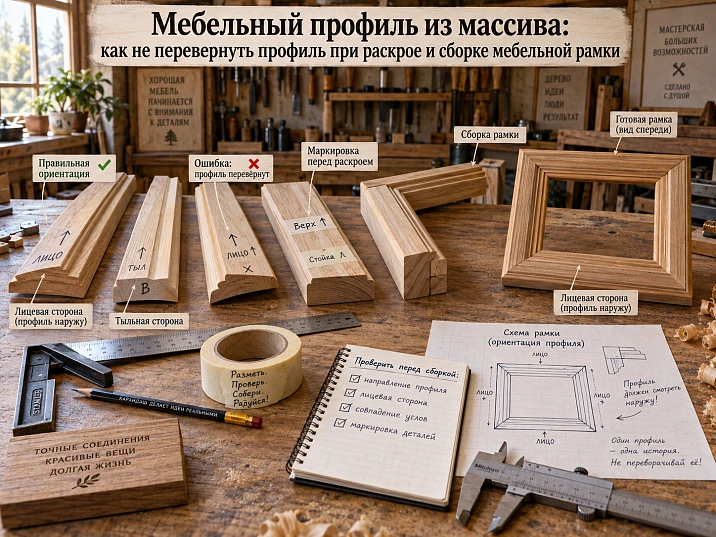
Four strips have already been cut, the outer rectangle came out the right size, but at one corner the relief suddenly breaks off. The cause may be quite simple: one side of the frame was turned with its inner edge facing outward. Along a single line the joint looks closed, but the convexity of the adjacent parts no longer continues.
Solid wood furniture profile must be marked indicating its position in the finished product. Before the first cut, determine the face and mounting sides, choose the inner and outer edges, distribute the four sides of the frame, and preserve these markings during processing. After cutting, check the entire perimeter dry.
This order is especially useful for asymmetric moldings: their high side, bevel, or characteristic curve must occupy a consistent position relative to the center of the frame. A precise cutting angle solves only part of the task. The cross-section must also meet the adjacent cross-section correctly.
Next, a flat overlay frame on a furniture facade with a rectangular contour is considered. If the profile is installed at an angle to the base or forms a spatial transition, the joint scheme is calculated separately. A single designation of "45°" does not describe all equipment settings for such assemblies.
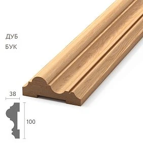
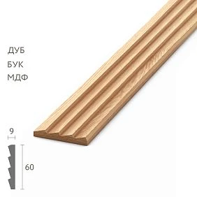
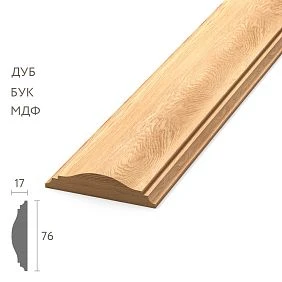
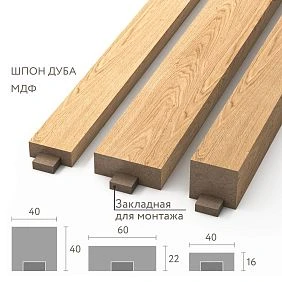
First, establish exactly what is symmetrical about the profile
Symmetry is checked against the cross-section. If the inner and outer edges are swapped while keeping the mounting surface on the base, will the profile shape remain the same? For a profile that is symmetrical about the middle of its width, this is possible. For an asymmetrical one, the position of the bulge, step, or bevel will change.
At the same time, symmetry of the face pattern does not allow the front and back to be swapped. The underside may contain the mounting plane, a rebate, or other areas that determine the fit. Their purpose is checked separately.
Even a simple decorative solid wood strip requires such a check if its edges are finished differently or the project specifies a particular visible side. The external simplicity of a part does not replace understanding its cross-section.




Cross-section dimensions do not set the installation direction
The size 25 × 20 mm gives the overall dimensions but does not explain which edge should face the facade area. Two positions of the same profile can occupy the same area and produce a different relief around the perimeter.
Next to the facade view, draw a cross-section of the assembly. Show the base, the mounting surface, the protruding profile, and the direction toward the center of the frame. For repeatable work, such a diagram is more useful than the verbal instruction “wide part that way.”
The documentation for the specific model is used as the basis. In the section drawings and models STAVROS you can look up the geometry of the product, but its position within your own frame must be fixed in the project itself.
A photograph of a single strip does not define the design intent. The same profile in different projects may be oriented differently if both options are structurally permissible and agreed upon.
Our factory also produces:
Choose a rule for the entire perimeter
The workshop should receive a short, verifiable instruction. For example: "the high edge faces the frame field" or "the narrow step runs along the outer contour."
These are examples of a possible solution, not a universal rule for any molding. It cannot be stated that the convex part must always face inward. The direction is chosen based on the cross-section, installation, and facade pattern.
After choosing, check the rule on each of the four sides. If the top strip complies with it but the bottom one is turned the opposite way, identical part codes will not save the composition.
For a complex profile, it is useful to attach a short sample to the cross-section diagram. Mark the characteristic edge on the sample: it is precisely its position that the craftsman will recognize during layout and after transfer to the equipment.
Get Consultation
Four designations remove ambiguity
For a single frame, the words "face," "mounting side," "inward," and "outward" are sufficient. They describe different directions and do not replace one another.
| Designation | What it means |
|---|---|
| Face | Surface visible from the front side of the facade |
| Mounting side | Surface facing the base in the selected node |
| Inward | Edge facing the central field of the frame |
| Outward | Edge facing the outer contour of the frame |
The “top” marking refers to the position of the entire part in the product. It does not indicate which edge of this part should be the inner one.
Specify all frame side designations when looking at the front side of the facade. If the craftsman is looking at the back side, the visual left and right are reversed. The saved part numbers remain unchanged.
The position of the inner edge changes on each side
On the top horizontal, the inner edge is at the bottom, and on the bottom horizontal, it is at the top. This is normal: the profile rotates around the perimeter while maintaining its relation to the frame field.
| Frame side when viewed from the front | Direction of "inward" | Direction of "outward" |
|---|---|---|
| Top | Down, toward the field | Up, away from the field |
| Right | Left, toward the field | Right, away from the field |
| Bottom | Up, toward the field | Down, away from the field |
| Left | Right, toward the field | To the left, from the field |
If the high edge is selected as the inner edge in the project, it follows exactly these directions. The requirement "high part always on top" does not suit a rectangular frame: it describes the position in the room, not the construction of the perimeter.
Therefore, the arrow on each part is tied to the center of the frame. A single common marker on the bundle is not enough.
Lay out the future sides before final cutting
Mark which sections of the source strips will produce the top, bottom, and two verticals. Place them next to the facade diagram in their intended position, face side toward the observer.
Whole long strips may extend beyond the layout boundaries. At this stage, the direction of the cross-section and the purpose of the sections are checked. The exact closing of the frame will be achieved after cutting.
Go around the perimeter sequentially: top, right side, bottom, left side. On each, check the mounting surface and the selected inner edge. Then mark the position of the future parts.
If you first cut the blanks without these marks, a short segment can easily be mistaken for one suitable for any side. Especially if it lies in a common box and already has one angled end of unknown purpose.
Length is measured along the pre-selected edge
For a part with two 45° cuts, the outer and inner edges have different lengths. Therefore, the entry "horizontal 620 mm" requires clarification: along which side was this dimension measured?
Let's take a conventional flat rectangular frame with external dimensions of 620 × 820 mm. The visible profile width is constant and equal to 25 mm, the corners are joined at a 45° miter, and there are no additional protrusions beyond the outer contour. The internal opening will be:
620 − 2 × 25 = 570 mm in width; 820 − 2 × 25 = 770 mm in height.
Thus, for the horizontal piece, the outer edge is 620 mm long and the inner edge is 570 mm. A confused reference base produces a 50 mm difference, even though in both cases the craftsman carefully measured the specified number.
On the diagram, indicate the measurement rule and the side of the retained piece relative to the cut line. The allowance itself and the kerf width are accounted for separately in the cutting map.
On a single piece, you also need to distinguish the left and right ends in its final position. In the schedule, it is useful to show both, including the direction of the angled cut. The entry “two 45° cuts” without a view of the piece allows several interpretations and does not explain where the long edge should end up.
Marking must remain on every cut piece
For the first front, use clear labels: “Front 01 — top”, “Front 01 — right”, “Front 01 — bottom”, “Front 01 — left”. Next to them, designate the inner edge and the mounting side.
If short codes are needed, the key must be provided in the same schedule. The symbol “П” without explanation can easily be read both as “right” (правый) and as “front” (передний).
Marks are placed in an area where they will not damage the visible finish and will not contaminate a critical glue contact. If necessary, use separate labeled cells or tags. An arbitrary marker may be a poor choice for a surface intended for light tinting.
Before cutting, check that the marking will not end up in the waste. Before sanding, transfer it to an accompanying record if the operation itself removes the mark.
Rotating on the table and flipping the part are different actions
The bar can be rotated in the plane while keeping the face visible, or it can be flipped face down. You can also change which longitudinal edge faces the stop. These actions change the position of the workpiece in different ways.
The phrase "turn it over for the second cut" is therefore insufficient. The working diagram must show which surface rests on the table, which edge serves as the reference, and which part of the workpiece is kept after the cut.
For specific equipment, different methods of producing the required end are acceptable. The chosen method is verified against the machine instructions, the profile geometry, and a test part. A universal command to "always place face up" for any profile and any equipment would be unreliable.
After each change of position, check three features: the face, the inner edge, and the purpose of the part in the frame. This is faster than reconstructing the meaning of a cut already made.
The left and right verticals are equal in length but each has its own place
On the front, the inner edges of the two verticals face each other. If identical parts are placed side by side on the table in the same orientation, this relationship to the frame is not yet visible.
The problem appears when the craftsman transfers the position of one vertical to the other based only on length. He obtains a suitable size but may change the direction of the profile or leave an incorrectly oriented mitred end.
Check each vertical according to its place in the diagram. The required position on the saw is determined by the chosen technology: some fixtures allow one reference to be maintained, while others require a change of setup. Equal length alone does not provide the answer.
The same rule applies to the upper and lower horizontals. Before the second cut, it is especially useful to read the "inward" mark once more rather than relying on the previous part from memory.
A test corner checks the meeting of two sections
Before the main batch, prepare two test offcuts of the same profile. Their length must allow standard fastening and processing on the equipment used. A random offcut that is too short is not suitable for this task.
Cut and join the offcuts without final gluing. Check the outer edge, the inner edge, the position of the mounting surfaces and the continuation of all visible relief lines.
A joint closed along only one line does not yet confirm a correct connection. With an asymmetric profile, a reversed orientation can produce a step or a mismatch of the end-face sections at another height.
Compare the resulting corner with the section diagram. If the result is accepted, keep it together with the orientation marking. It will become a clear answer to the question of how adjacent sides should meet.
MLD-014: why a single size of 25 × 20 mm is not enough
In the product card of the MLD-014 moulding a section of 25 × 20 mm is specified. Beech and oak versions are offered in a length of 2400 mm, the MDF version — 2600 mm. For a solid wood project, select the appropriate material even if the model name remains the same.
Work with this model begins with a specific section sample: place it against the base, identify the mounting surface and mark the edge that, according to your drawing, should face into the frame field. The entry “MLD-014, 25 × 20” does not contain this decision by itself.
If an additional rebate is provided, it is also shown on the assembly section. The location of the mounting surfaces cannot be transferred from the standard version to the modified one without verification.
This example does not define a single correct position for the molding. It shows what information must supplement the article number before the frame is manufactured.
One successful corner does not confirm the other three
After cutting, dry-assemble the entire perimeter on a verified flat surface or on the base provided for by the project. Mark the corners so that you inspect them in the same order.
For each corner, check in sequence:
- Whether the correct sides of the frame have met each other.
- Whether the position of the face and the mounting surface is preserved.
- Whether the selected inner edge continues.
- Whether the characteristic section lines match.
- Whether the ends meet without forced bending of the parts.
Then evaluate the frame as a whole: outer dimensions, inner contour, flatness, and squareness. Clamping may temporarily hide a problem, but it does not turn an incorrect section into a correct one.
Do not mark the set as verified after a single good corner. A flipped bottom horizontal will affect two adjacent joints at once.
Light helps locate a suspicious area, but it does not deliver a verdict.
Side lighting makes the relief more noticeable. You can see a suddenly broken bulge, a step, or a change in the character of the transition at a joint. During inspection, it is useful to rotate the dry frame relative to the light source.
However, correctly assembled top, bottom, and verticals do not have to cast the same shadow. Their surfaces are oriented differently relative to the lamp. A difference in light and shadow does not by itself prove that one strip is flipped.
If an area looks suspicious, return to the geometry: compare the position of the marked edge, the cross-section, and the continuation of the lines at the corners. If necessary, inspect the opposite side in a comparable position relative to the light.
For example, a dark band only on the bottom horizontal may be explained by overhead light. If, at the same time, the selected rebate runs along the inner contour of all four sides and the lines converge at the joints, there is no reason to flip the bottom piece just for uniform brightness.
The criterion for correctness is compliance with the approved scheme. Lighting helps notice a reason for checking, but it does not replace it.
What to do if one side was turned around
Stop assembly and find which condition is violated. Sometimes only the place of the part is mixed up: it was intended for the other side. In another case, the ends are cut so that, with the correct orientation, the strip no longer fits.
First try to restore the intended layout by marking without machining. If re-cutting is required, check whether the required finished length will be preserved. Additional trimming shortens the part; it cannot be considered acceptable just because the profile now faces the right way.
Separately check the case where the section direction is correct but a gap remains between the ends. Here the cause may be the cut angle, non-flatness of the part, or an inaccurate length. Rotating the profile will not fix such an error. Compare the reference edges with the sample, check the fit on the base, and only then decide what exactly needs to be corrected.
If the size cannot be restored, make a replacement and update the list. With a transparent finish, compare the new part with the others by tone and texture.
A shape error should not be masked with finish or joint filler. First correct the orientation and geometry, then confirm the external result of the entire frame.
Oak for tinting adds a check of the wood grain
An oak frame with an open texture has two conditions: the correct position of the profile and a consistent perception of the wood. Geometry is confirmed first. You may rotate an already assigned strip for a beautiful grain only within the limits permitted by the section and the end pattern.
Lay out all four sides together before finishing. Do not promise a continuous grain pattern at every corner: adjacent parts change direction, and natural material is not uniform.
The more practical task is to avoid a random combination in which one side stands out sharply from the overall appearance. After a test coating, check whether the accepted combination has been preserved.
For paired fronts, look at both frames at the same time. Two compositions that are well assembled individually may look inconsistent next to each other if the texture was selected without considering the overall appearance of the furniture.
Enamel hides the color of the wood but preserves the shape
A beech furniture profile for enamel can be selected with less attention to the natural shade. The orientation of the section, however, is checked fully: the paint layer does not correct a reverse bevel or a broken relief line.
On the page quality of STAVROS products blanks for enamel and for tinting are separated. The differences in the selection of lamellas relate to the future appearance of the wood. They do not replace the requirements for the shape and assembly of the unit.
Before starting painting, confirm the dry frame, and then check the selected finish on a sample. If the geometry was approved in one position, that exact position must be preserved when handing over to the painter.
The finish code and the designation of the installation scheme are recorded separately. A color change must not imperceptibly turn into a new orientation rule.
A section sample and a test corner serve different purposes
In the section samples of trim products STAVROS lists pieces 100 mm long. They allow you to examine the profile and place it against the facade. The sample material must be clarified: MDF, beech, and oak are possible.
For comparing different sections, there is Molding samples set OMLD-005. The set description lists 85 molding samples 100 mm long made of oak, beech, and MDF.
Such a selection is convenient for choosing and approving a shape. But the presence of a short sample does not mean that a full-fledged pair of test parts for your cutting technology can be obtained from it. Material for the test corner is provided separately, taking into account fastening, cuts, and the required length.
For a series, keep an orientation card
For ten identical facades, the section direction must not depend on who carries the planks to the saw today. After the first product is approved, save a card with a clear scheme.
| Card field | What to fix |
|---|---|
| Profile | Article number, cross-section, material and finish |
| Product view | From the front surface side of the facade |
| Mounting side | Marked surface on the section |
| Inner edge | Distinctive cross-section feature facing the panel |
| Outer edge | Cross-section feature on the outer contour side |
| Frame sides | Top, right, bottom, left with part numbers |
| Ends and dimensions | Cutting diagram and length measurement rule |
| Control | Approved trial angle and four-corner check |
| Finishing | Finish code and reference to the approved sample |
Assign the card a number, for example "Orientation 01", and a revision date. Attach a photo of the signed frame and a cross-section diagram. A photo without annotations leaves too much room for guesswork.
The first front becomes the reference only after a full check
Do not start a run based on the first successfully cut pair. Check a complete frame, its position on the front, all four corners, and the approved finish in the quantity required for the project.
After confirmation, designate a control specimen or keep a sufficient set of diagrams and samples. Before repeating, verify the material and configuration of the incoming profile against this documentation.
The production specification needs separate entries: which product is used, which four parts are made from it, and by which card the frame is assembled. A single line "molding — twelve meters" does not contain this information.
If the orientation has been changed, correct not only the drawing but also the processing instructions. Old signed parts must not be automatically mixed with the new run: first check whether they can be used.
A different profile requires a new check
A similar width of two models does not confirm the same mounting plane, symmetry, or relief position. When changing the item code, review the cross-section again, identify the edges, and assemble a test corner.
for carved wooden moulding additionally check the longitudinal direction and the position of the ornament. The correct orientation of the cross-section does not yet guarantee that the decorative motif matches at the joint.
If, instead of the selected product, you decided Buy solid wood molding on a different configuration, treat this as a specification change. The previous control corner remains a sample of the previous solution only.
Also keep offcuts with the item code, cross-section, material, and orientation marking. An angled end without a labeled purpose does not explain for which corner the part was prepared.
Before installation, reconstruct the approved layout once more
After sanding and painting, the four sides must return to their facade. Lay them out by number, check the inner edge, and make sure that a similar offcut from another frame has not ended up in the set.
The fastening order depends on the base and the condition of the surfaces. In STAVROS installation tips unfinished and already finished surfaces differ. The specific composition and technique are chosen for your particular joint.
Before final fastening, prepare suitable Mounting and finishing materials and the intended clamp. Installation must not become a way to force together mixed-up or incorrectly cut parts.
At this stage it is useful to have an orientation card nearby: the finished relief may be perceived differently, but its position relative to the frame field must remain the same.
Where to buy solid wood furniture profile
Select solid wood furniture profile for the frame it is convenient to use a specific section and sample. Before ordering a batch, confirm the article number, dimensions, wood species, blank finish and commercial length.
If you need to buy wooden moldings for furniture for a recurring project, attach a list of parts and provide material for a test corner. First confirm the chosen orientation on the first facade, then set the rule for the entire series.
For regular purchases, review conditions for manufacturers, and before placing an order — payment and deliveryAdditional processing and assembly according to your specifications are quoted separately.
A ready-to-use kit consists of four labeled parts, a profile position diagram, and verified angles. With this preparation, the craftsman preserves the frame's design at every transfer: from the original strip to the saw, from the saw to finishing, and from finishing to the facade.