Article Contents:
- Short answer: the number of KZ-001-11 is determined by the cutting map, not by a single total length
- Confirmed characteristics of KZ-001-11
- What exactly is added to the cart
- Why perimeter and specification are different values
- The theoretical minimum is needed, but only as a reference figure
- Measurements are taken along the actual installation line of KZ-001-11
- The wall schedule turns the room into a set of verifiable sections
- Before cutting, the plan version and DWG are fixed
- The most visible walls receive the best whole sections
- How to work with a wall longer than 2400 mm
- Joint off the central axis
- Two approximately equal sections
- Long main fragment and short extension
- One straight section is shorter than 2400 mm
- A regular room with four walls
- A complex object with niches, portals, and columns
- Mistake 1. Dividing the perimeter by 2.4 and buying immediately
- Mistake 2. Measuring the room by the floor
- Mistake 3. Not planning joints in advance
- Mistake 4. Assembling the main wall from short leftovers
- Mistake 5. Considering any leftover suitable
- Mistake 6. Inventing an insertion repeat
- Mistake 7. Transferring KZ-014 technology
- Mistake 8. Not marking the direction
- Mistake 9. Ignoring external corners
- Mistake 10. Mixing batches
- Mistake 11. Painting before a dry fit
- Error 12. Expecting individual cutting from STAVROS
- Error 13. Confusing architectural profile with curtain rod
- Error 14. Not keeping repair allowance
- What is the length of one KZ-001-11 strip?
- Why can't you simply divide the perimeter by 2.4?
- What does the theoretical minimum show?
- Where is the best place to place the joint on a long wall?
- Can a joint be placed in the center of the wall?
- How to account for an internal corner?
- Why is an external corner more complex than an internal one?
- Can short offcuts be used?
- Does the insert have a confirmed pattern repeat?
- Is the insert supplied separately?
- What material should the cornice be ordered in?
- Is it necessary to order a spare plank?
- Does STAVROS provide custom cutting?
- When should the final measurement be taken?
- What to do if the wall size changed after ordering?
- How to accept oak planks?
- Is it possible to fully paint the parts before fitting?
- What documents should be handed over to the installer?
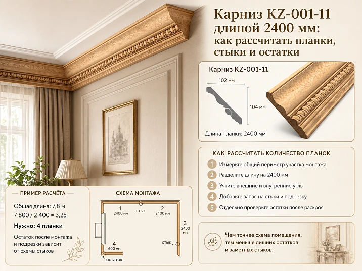
Buy wooden cornice KZ-001-11 For the ceiling perimeter, portal, built-in furniture, or a complex wall composition, it is only worth doing after a piece-by-piece layout of the original slats 2400 mm long. Simply dividing the total footage by 2.4 shows only the theoretical minimum. It does not answer the main questions of the order: where the joints will be, how much length will go to internal and external corners, whether the remainder can be transferred to a niche, whether a seam will fall in the center of a prominent wall, and how the decorative insert will behave at the connection point.
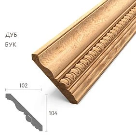
KZ-001-11 is a wooden cornice with an insert with a confirmed cross-section of 104 × 102 × 24 × 17 mm and a length of 2400 mm. The product card provides for execution in beech or oak, "Prestige" sanding, preparation of beech for enamel and oak for tinting. STAVROS does not perform cutting of this item to individual customer sizes, so whole products are added to the cart, and the wall list, joint map, and cutting plan are prepared by the designer or installer.
Proper specification begins not with the line "perimeter — 16 meters," but with a list of sections: central wall, side walls, niche, column, protrusion, short return, portal, place of adjoining the cabinet. Each section is assigned a code, the actual length along the installation line, the type of ending, and the permissible position of the joint are indicated. After that, the most visible zones receive whole or maximally long pieces, and suitable remnants are distributed to short sections. This approach helps to order a sufficient quantity of KZ-001-11 without accidental excess and without a shortage of one slat at the end of installation.
Short answer: the quantity of KZ-001-11 is determined by the cutting map, not by one total footage
The theoretical minimum is calculated by dividing the total length of all sections by 2400 mm and rounding up. But you can place an order based on this number only when the cutting map really confirms that each wall is assembled from the obtained segments, corner cuts are taken into account, and remnants can be transferred between sections. In a complex room, such a coincidence does not always happen.
- First measure the actual installation line on each wall.
- Then mark internal corners, external corners, end terminations, and interruptions of the cornice.
- After that assign acceptable and undesirable joint zones.
- Next lay out whole planks of 2400 mm length and assign codes to all segments.
- Only at the end count the number of original products KZ-001-11 and make a decision about a spare plank.
A universal percentage allowance does not replace this work. For one room, an additional strip may be justified by an external corner and a complex insert, while in another project surplus arises already with rational distribution of offcuts. The decision should follow from the specific cutting layout.




Confirmed characteristics KZ-001-11
| Parameter | Confirmed value | What to check before ordering |
|---|---|---|
| Article number | KZ-001-11 | Keep the exact designation in the plan, specification, and marking. |
| Product type | Wooden cornice with insert | Do not transfer the construction of another model to it without checking the drawing. |
| A | 104 мм | Verify the purpose of the dimension arrow against the current DWG. |
| C | 102 мм | Check the profile offset relative to the wall, ceiling, and furniture. |
| D | 24 мм | Consider it as part of the section only according to the product drawing. |
| E | 17 мм | Do not guess the parameter location from a photo. |
| L | 2400 мм | This is the length of one original strip, not the length of any finished section. |
| Material | Beech or oak | Select one breed for the agreed perimeter, unless otherwise specified by the project. |
| Sanding | «Prestige» | Match the preparation with the future finish and the painter's requirements. |
| Beech finish | For enamel | Specify the covering finish system and make a test coat. |
| Oak finish | For tinting | Coordinate the tone, coating transparency, and texture visibility. |
| STAVROS cutting | Individual cutting is not performed | Order whole planks and prepare your own cutting map. |
| Technical documentation | A drawing is available for the product. | Record the used DWG version in the project documents. |
The numbers in the card describe the product but do not replace the design section. Before approving the ceiling line, it is useful to download the DWG and the wooden trim catalog, compare all arrows and ensure that the profile extension does not conflict with doors, curtains, built-in wardrobes, light fixtures, and engineering grilles.
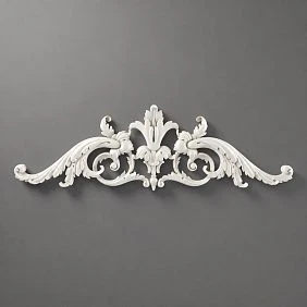
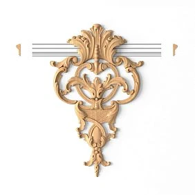
Our factory also produces:


What exactly is added to the cart
| The buyer receives | Not included automatically | Who is responsible for the result |
|---|---|---|
| One strip KZ-001-11 | Finished room perimeter | The designer compiles a list of sections. |
| The original length of 2400 mm | Cutting by wall lengths | The installer performs cutting according to the approved map. |
| Confirmed cross-section | Ready-made internal and external corners | Corners are marked according to the actual geometry of the room. |
| Beech or oak | Automatic color matching for the entire finish | The designer and painter agree on a coating sample. |
| Prestige sanding | Final finishing of the entire perimeter | The contractor follows the chosen painting or tinting system. |
| Cornice with insert | Guaranteed seamless pattern match | The joint is checked against the actual product, sample, or DWG. |
| Separate product line item | Installation, marking, and storage of segments | These operations are included in the work order. |
Such a distinction is especially important when transferring an order between the designer, the kit assembler, and the installation crew. The product card confirms the parameters of the strip but cannot know the geometry of a specific room. The more accurately the project separates supply and installation operations, the lower the risk of expecting a turnkey solution from a single product item.
Get Consultation
Why perimeter and specification are different values
In casual estimates, a single figure is often used: "18 meters of cornice needed." This is insufficient for purchasing KZ-001-11. Behind one figure, at least six different values are hidden:
- Geometric length — the sum of the finished lengths of all sections along the installation line.
- Theoretical number of planks — geometric length divided by 2400 mm and rounded up.
- Useful yield — the length of segments that can actually be used after corner and straight cuts.
- Technological losses — sections used for fitting, damaged ends, test cuts, and corrections.
- Usable remnants — segments with clear direction, intact face surface, and sufficient length for another section.
- Final number of source planks — the number of whole items from which the cutting map assembles the entire project.
If you mix these concepts, a remainder of 420 mm in length may be mistakenly considered a full resource for returning 400 mm, without checking the corner end and insertion direction. Or, conversely, suitable pieces are not taken into account at all, and extra products are ordered. An item-by-item map makes the calculation verifiable: each source has a number, and each obtained element has a purpose.
A theoretical minimum is needed, but only as a reference figure
It is convenient to write the lower bound as a formula:
Nmin = rounding up the sum of section lengths / 2400 mm.
This figure helps to quickly spot a rough error. If the total footage is 14,100 mm, it is impossible to buy fewer than six planks: five products give only 12,000 mm of initial length. However, six planks do not yet guarantee that the project will assemble. It may turn out that three long walls require separate solid fragments, and the remaining pieces have unsuitable corner ends.
It is useful to compare three values: the theoretical minimum, the number of planks from the first layout, and the number from the optimized layout. If optimization reduces the order, you need to check whether the position of noticeable joints has worsened. Saving one plank is not always justified when the central wall turns into a set of short pieces.
Measurements are taken along the actual installation line of KZ-001-11
Measuring along the floor or along a conditional rectangle from the plan often gives an incorrect result. The cornice is located higher and has its own projection. Protrusions may appear on its line that are not present below, or, conversely, part of the wall is hidden by built-in furniture. Therefore, all dimensions are taken where the profile will actually run.
- The finished level of the ceiling and walls is marked after the main finishing layers are completed.
- Columns, boxes, niches, beams, portals, and furniture ends are checked.
- They mark the places where the line is interrupted by a ventilation grille, door portal, or other element.
- They check the curvature of long walls and the parallelism of opposite sections.
- For complex angles, templates are made rather than recording them as automatic 90°.
- They indicate where the cornice ends with an open end, and where it returns to the adjacent plane.
It is convenient to take measurements together with a side section. KZ-001-11 has a large cross-section, so knowing only the wall length is not enough: it is important to see where the profile goes in height and depth. If a general scale selection is required, the material is useful how to choose a wooden cornice for the interior; this article assumes that the model has already been selected and the task at hand is specifically cutting.
The wall schedule turns the room into a set of verifiable sections
Each line is assigned a short code. Walls can be marked C-01, C-02, and C-03, niches — N-01, returns — R-01, columns — K-01, portal — P-01. The code must be repeated on the plan, in the cutting table, on the label of the finished piece, and in the installation diagram.
| Code | Section | Finished length | Start | Ending | Joint condition |
|---|---|---|---|---|---|
| C-01 | Central wall | By measurement | Internal corner | Internal corner | Do not place the joint on the main axis. |
| C-02 | Side wall | By measurement | Internal corner | End near the cabinet | Joint is acceptable closer to the furniture. |
| H-01 | Niche | By measurement | External corner | Internal corner | Check the insertion direction. |
| V-01 | Short return | By measurement | External corner | Open end | Do not use the remainder with a damaged end. |
| K-01 | Column bypass | By measurement | External corner | External corner | Assemble the pattern of all faces. |
| P-01 | Area above the portal | By measurement | As per project | As per project | Align symmetry relative to the opening. |
The list allows discussing the project without phrases like "that small piece on the right." If a size change is detected during installation, the specific line is corrected. Then only the related source strips and remainders are recalculated.
Before cutting, the version of the plan and DWG is fixed.
Room dimensions change after wall leveling, furniture installation, or clarification of the ceiling structure. At the same time, the product's technical file may be updated on the website. Therefore, the work card must contain the measurement date, the version number of the interior plan, and the designation of the used drawing KZ-001-11.
In practice, a simple header is sufficient: "Room plan v3, measurement from 07/26/2026, DWG KZ-001-11 — file received when placing the order." If the contractor receives an update, the old card is not deleted without a trace but is marked as inactive. This prevents a situation where the workshop cuts slats according to one document, while the installer opens another.
The most visible walls get the best full-length sections
Cutting begins not with short returns, but with compositionally important lines. The central wall of the living room, the area above the portal, the long line in the hallway, or the front of the built-in bookshelf are usually considered first. For them, a full slat or the longest possible fragments with a pre-assigned joint are selected.
This differs from mathematical packing, where the program aims to minimize waste at any cost. In interior design, joint quality has its own priority. It is acceptable to have a slightly larger remainder if, due to this, the joint moves from the center of the wall to a less noticeable zone. Therefore, it is useful to have a "visual priority" column in the card: high, medium, or technical.
How to work with a wall longer than 2400 mm
If the finished section is longer than one slat, a joint is inevitable. But its coordinate should not appear randomly as a remainder of arithmetic. First, a zone is chosen where the joint is less noticeable and does not conflict with the decorative axis. Then, it is checked what lengths are obtained on the left and right and whether the remainders can be used on other sections.
Joint off the central axis
On a symmetrical wall, a joint exactly in the center can be especially noticeable: it is emphasized by a chandelier, fireplace, TV zone, or portal. Shifting it to the side often makes the line calmer, but it must be deliberate. You cannot mechanically move the joint to the corner if a complex cut begins there and a too-short fragment remains.
Two approximately equal sections
Sometimes the composition requires balance, and two fragments of similar length look better. This solution is checked on the wall layout. For the insert, additionally assess how the joint line of the decorative band reads. Without information about pattern repeat, a perfectly invisible match cannot be guaranteed.
Long main fragment and short add-on
This scheme is convenient when the short add-on can be tucked away near a wardrobe, curtain, side wall of a portal, or another inconspicuous area. But the segment should not be so short that it is difficult to fit precisely and install reliably. The minimum practical length is determined by the installer based on the specific geometry and installation method.
Internal corners are measured according to actual geometry
Even in a new room, walls rarely meet at exactly 90°. The error is especially noticeable on large wooden profiles. Therefore, the angle is checked with a template or measuring tool, and the cut line is set according to the actual section KZ-001-11.
A diagonal cut consumes the original length differently than a straight cut. In the wall schedule, it is not enough to record only the finished length between corners; the installer needs an allowance for fitting and an understanding of which reference point the dimension is taken from. It is reasonable to check the first complex corner on a test piece or leftover suitable for tool adjustment.
General principles of joining and surface preparation are covered in the material about types of profiles and installation of wooden cornices. In card KZ-001-11, not a universal cut angle is recorded, but the specific measurement result of each joint.
External corner requires a separate resource for checking
The external corner is in plain sight and highlights any profile discrepancy. Here, geometric accuracy, preservation of the front edge, and continuation of the decorative insert are all equally important. One cannot assume that two segments will "somehow meet" after painting.
- Each side of the external corner is assigned a separate code.
- On the segment, the top, bottom, and direction along the perimeter are marked.
- Before the final cut, the corner template is checked.
- The front surface is protected from chips and press marks.
- The insert joint is evaluated during a dry assembly.
- After a successful fit, the result is photographed and transferred to the installation documentation.
If the project contains several identical external corners, the first one becomes the reference sample. But even then, each subsequent corner is checked on site: construction geometry may differ.
Niches cannot be counted as a single line of the overall perimeter.
A niche adds at least three sections: the front line and two short returns. It introduces external and internal corners, and the direction of the cornice changes several times. The total footage may be small, but the number of cuts and requirements for offcuts increase.
For a niche, it is useful to draw a separate enlarged diagram. It indicates the depth, width, each face, and the traversal order. Then decide which elements are more advantageous to cut from a single plank, and which from remnants after long walls. Not only the size matters, but also the type of both ends. A remnant with one already made corner cut is suitable only when its orientation matches the new section.
A short return is checked as an independent part
A return at a built-in wardrobe, box, or portal often seems like a convenient place for any remnant. This is a dangerous simplification. The piece must have sufficient length, an intact face surface, a suitable insertion direction, and ends from which the required finishes can be obtained.
If a return ends with an open end, its appearance is additionally considered. A random offcut with a damaged edge cannot be assigned just because its nominal length is greater than the size of the section. In the remnant map, the condition of each end is recorded separately.
Going around a column or box is a group of faces
A column cannot be described with a single figure "perimeter 1.6 m". The four faces may differ in length, and the corners in actual size. In addition, one side is often perceived as the main one, while another recedes into the shadow. Therefore, the traversal gets its own set of codes: K-01A, K-01B, K-01V, and K-01G.
First, the front face is assigned and it is decided whether a solid piece is needed on it. Then the side and back sides are distributed. This order allows using remnants without degrading the most visible surface. For each pair of external corners, a dry fit is performed.
Built-in furniture can interrupt or continue the cornice line
If the wardrobe reaches the ceiling, KZ-001-11 may end at its side, go around the body, or transition to a furniture cornice — depending on the project. These scenarios cannot be mixed. The statement records the exact end point and the type of junction.
It is especially important to check the 102 mm profile overhang according to the drawing. The cornice must not interfere with the opening of upper doors, lift-up facades, or access to service hatches. A flat room plan does not show such conflicts; a section is needed.
The decorative insert makes the joint a separate design task.
With a regular smooth molding, attention is focused on matching the main profile. With KZ-001-11, you additionally need to evaluate the decorative line. Available data confirm the presence of the insert in the product name, but do not provide its repeat, the length of one motif, the method of formation, or the possibility of seamless joining.
Therefore, the correct procedure looks like this:
- Open the current drawing and check what information about the insert is shown in it.
- Obtain a physical sample or two fragments of the product, if possible within the order.
- Join the fragments in the intended direction.
- Evaluate the alignment of the main profile and the decorative band.
- Determine acceptable joint zones and the required length for fitting.
- Record the orientation of each original plank in the cutting map.
You cannot write "match the repeat" in the task if the repeat itself is not confirmed. The correct wording is: "check the visual continuation of the insert based on the actual product and agree on the connection line."
The KZ-014 structure cannot be transferred to KZ-001-11
Cornice KZ-014 with a separate decorative frieze has its own confirmed structure and technology. There is a separate material about how to order KZ-014 with separate painting and frieze insertion. This information cannot be automatically applied to the wooden KZ-001-11.
In the article and installation task for KZ-001-11, it cannot be stated that the insert is supplied separately, glued in after painting, or allows two-tone finishing, until this is confirmed by the card, DWG, or official consultation. The similar word "insert" does not mean the same structure.
KZ-001 without the insert helps to check whether the complex version is needed
If the decorative band creates unwanted complexity in connections, you can look at the wooden cornice KZ-001 without the decorative insertCoincidence of the main cross-section does not mean full interchangeability: the base model may differ in materials, lengths, and design variants. However, comparison helps to honestly answer the question of whether the project specifically needs the KZ-001-11 accent.
Another version with an insert — KZ-001-4 — is also considered only by its own card. The modification number cannot be used as confirmation of the same pattern, repeat, or joining method.
The direction of each plank is marked before the first cut
Even if the profile visually appears symmetrical, the direction must be recorded. On the source, the plank number, conditional "left" and "right" ends, top, and face side are marked. After the first miter cut, this information becomes critical: the remainder can no longer be freely rotated without checking the decorative line.
Marking is done on the protected back area or on a removable label that is preserved after priming. The card records the origin of each piece: P-03/A means part A from source plank No. 3. If the installer finds a problem, the entire chain can be traced.
The source plank map must be a separate table
| Plank | Material | Source length | Main section | Additional section | Remainder |
|---|---|---|---|---|---|
| P-01 | Per order | 2400 мм | S-01, left part | No | Record after cut |
| P-02 | Per order | 2400 мм | S-01, right part | B-01 when ends match | Record after fitting |
| P-03 | Per order | 2400 мм | C-02 | N-01A | Mark separately |
| P-04 | Per order | 2400 мм | P-01 | N-01B | Save as backup |
| P-05 | Per order | 2400 мм | K-01A and K-01B | Test corner | Do not consider suitable until inspection |
The table above shows the structure, not a ready-made layout for a specific room. The numbers of sections are filled in after measuring. It is important that each plank has a primary purpose. Short pieces should not "take" the best source materials before long and visible walls are ensured.
The remainder receives its status only after the actual cut
In the preliminary layout, the remainder can be predicted, but the final status is assigned after fitting. The actual length may decrease due to angle adjustment, chip removal, or re-cutting. Therefore, during installation, the remainder is measured again.
| Remainder code | Actual length | End 1 | End 2 | Front surface | Solution |
|---|---|---|---|---|---|
| O-01 | As per actual | Straight | Corner | No damage | Check for return with suitable orientation. |
| O-02 | As per actual | Straight | Straight | No damage | Consider for niche or technical wall. |
| O-03 | As per actual | Corner | Chipping | Partially damaged | Use as finish or settings sample. |
| O-04 | As per actual | Straight | Straight | Texture selected | Save as repair reserve. |
Suitability is determined not only by length. The segment must match the material, shade, insertion direction, and type of required ends. For oak, the wood grain on the visible joint is additionally assessed.
Conditional example: rectangular room without protrusions
Suppose that after the final measurement, four sections are obtained: 3700, 3700, 2900, and 2900 mm. The total length is 13,200 mm. The theoretical minimum is six planks: 13,200 / 2400 = 5.5, rounded up.
But then the actual layout is performed. Two walls of 3700 mm each can be assembled from fragments of 2400 + 1300 mm. Two walls of 2900 mm each — from 2400 + 500 mm. In a simplified scheme without losses at corners, six planks provide sufficient length if two remainders of 1100 mm after the long walls allow obtaining the necessary segments of 500 mm. However, before ordering, you need to check:
- whether the selected coordinates of the four joints are acceptable;
- what ends will be required for the 1300 and 500 mm fragments;
- how much length will be consumed by actual corner cuts;
- whether the remainders can be used while preserving the insertion direction;
- Is a trial or repair resource needed?
This example demonstrates a method, not recommending six planks for any room with such a perimeter. After accounting for corners and a decorative line, the order may change.
Conditional example: a room with a niche
To the four main walls, we add a niche 1200 mm wide and 350 mm deep. The list gains three new sections: a front of 1200 mm and two returns of 350 mm each. The total length increases by 1900 mm, but complexity grows more because two external and two internal corners appear.
In a mathematically compact layout, returns can be cut from short remnants. In practice, their ends are checked first. If both remnants after the main walls already have corner treatment of an unsuitable direction, a different source is needed. Therefore, the niche is considered before final approval of the planks, not trying to "assemble from what remains."
Conditional example: a central portal and side returns
Let the main wall be 5200 mm long, but a portal is located in the center, above which a visually continuous line is required. The designer may decide that the joint should not coincide with the portal's axis. Then the simple scheme of 2400 + 2400 + 400 mm requires rework: a short fragment at the edge may be inconvenient, and two connections may be too noticeable.
Another layout is possible, for example, with two more balanced sections and transferring the remainder to a side return. Specific numbers are assigned after drawing the wall and checking the decorative insert. The point of the example is that the placement of joints shapes the number of planks no less than the total length.
When a reserve plank is truly justified
A reserve is not a universal percentage or an automatic line. Its necessity is confirmed by project risks. An additional whole plank is especially justified when:
- there are several external corners with high visibility;
- the decorative insert needs to be checked and adjusted according to the actual sample;
- installation takes place far from the delivery site, and quick additional purchasing is difficult;
- the project has many short sections with different types of ends;
- a transparent oak finish is used and matching of the wood grain pattern is required;
- part of the material is intended to be kept for future repairs;
- the room may still receive minor adjustments after the final measurement.
The reserve should not hide a weak layout. First, an optimal cutting plan is performed, then separately explained what task the additional plank solves.
When an extra strip may be unnecessary
In a simple perimeter with a small number of corners, the initial layout sometimes already creates a large usable offcut. If it has an intact face surface and is suitable for likely repairs, a separate reserve may not be needed. Such a decision should also be documented so that the savings do not look like an accident.
The order cannot be reduced below the layout just because "installers usually manage." If one section remains without a confirmed source, the specification is incomplete.
Beech and oak change not the length, but the requirements for the batch
| Criterion | Beech | Oak | Practical conclusion |
|---|---|---|---|
| Confirmed execution | For enamel | For tinting | The finishing system is chosen before placing the order. |
| Surface perception | Focused on opaque finishing | The texture may remain visible | For oak, the planks are distributed more carefully across visible walls. |
| Joint | After opaque finishing, attention is focused on geometry | Additionally, the wood grain pattern is readable | Oak joints are evaluated in a dry layout. |
| Batch | Preferably a unified finish | Tone and texture are especially important | It is better to complete one perimeter with a matched batch. |
| Sample for testing | Shows the color and quality of the enamel | Shows the tone and transparency | The sample is approved before finishing all parts. |
The card does not establish a universal superiority of one wood species. Beech is rational when the project is based on covering enamel; oak — when it is necessary to preserve the character of the wood under tinting. All material changes must be reflected in the card so that the remainder of one species does not end up in another perimeter.
Prestige sanding does not cancel the trial finish
The prepared surface remains part of the overall painting system. Before processing all slats, a control fragment is selected, the primer, enamel or tinting is checked, the filling of the relief and the condition of the ends are assessed. The current description of preparation levels can be verified on the page choose the preparation of a wooden cornice for finishing.
It is advisable to obtain a control sample from the same material and finish as the main order. On it, you can also assess how noticeable the joint line is after finishing. The result is recorded with a photo and a brief description of the coating composition.
A dry fit should precede the final painting
If all parts are fully finished before the first assembly, adjusting an angle or joint may damage the coating. Therefore, the workflow is divided: preliminary cutting with allowance, dry fit, refinement of ends, marking, then coordinated finishing and final installation.
The specific sequence depends on the coating and the contractor's technology. It is useful to study in advance recommendations for finishing and installation of wooden moldings, but the final procedure should take into account specifically KZ-001-11, the selected material, and the substrate.
Marking must survive painting work
After painting, visually similar elements are easy to confuse. Therefore, the code is duplicated on a removable label, packaging, and in the card. Do not apply a mark to the visible surface or use a method that will show through a transparent coating.
For a long perimeter, color grouping is useful: the central wall — one label color, the niche — another, the column — a third. Color does not replace the alphanumeric code but speeds up sorting on site.
What to buy and prepare together with KZ-001-11
The cornice cannot be considered separately from the drawing, finishing, and mounting base. At the same time, random fastener positions should not be added to the article without confirmed compatibility. It is more correct to form a list of categories and design materials that are checked before ordering.
| What to add to the project | Why | When required | What to Check |
|---|---|---|---|
| Current DWG KZ-001-11 | Check the section and dimension arrows | Always | File version and compliance with the card. |
| Mounting line plan | Record all walls, niches, and returns | Always | Final dimensions and measurement date. |
| Cutting map | Determine the number of whole planks | Always | Purpose of each source and remainder. |
| Corner templates | Account for actual geometry | For non-standard angles | Section label and orientation. |
| Test fragment | Check cut, insertion, and finish | For complex joints and coatings | Material, direction, and profile preservation. |
| Agreed preparation for finishing | Link product to painting system | Always | Beech under enamel or oak under tinting. |
| Installation materials | Pin profile to a specific base | As per project | Compatibility with the base and coating. |
| Repair remainder | Keep material from the same batch | For complex and long-term projects | Marking, storage conditions, and length. |
How not to confuse KZ-001-11 with a curtain rod
The key "wooden cornice" is often used for rods and guides on which curtains hang. KZ-001-11 belongs to architectural wooden moldings and decorates the transition of a wall, ceiling, portal, or furniture composition. It is not a ceiling rail, electric curtain rod, or textile holder.
Before purchasing, it is useful to open the category where you can buy a wooden cornice specifically as a decorative profile. This eliminates incorrect expectations about its purpose and helps compare KZ-001-11 with relevant models.
Who is suitable for per-piece calculation of KZ-001-11
| Situation | Is the method suitable | Why |
|---|---|---|
| Simple rectangular room | Yes | Even here, you need to assign four corners and connections of long walls. |
| Room with niches | Especially needed | Short returns and different types of ends appear. |
| Bay window or column bypass | Essential | The overall perimeter hides many individual faces. |
| Cornice around built-in furniture | Yes | Need to connect wall and furniture geometry. |
| One short straight section up to 2400 mm | Simplified | It is enough to check the ends, cross-section, and the absence of complex angles. |
| Order without final measurement | No | Quantity and cutting will be based on assumptions. |
| Attempt to obtain cutting from the manufacturer | No | For the item, it is confirmed that STAVROS does not perform custom cutting. |
When it's better to choose another solution
KZ-001-11 may not fit if the project is not ready to check the decorative insert at the joints, if the depth and height of the profile conflict with the placed
How to check the cart before payment
- The cart specifies exactly KZ-001-11, not the base KZ-001 or another version with the insert.
- The quantity reflects whole strips of 2400 mm length, not linear meters.
- One agreed material is selected — beech or oak.
- The execution corresponds to the future enamel or tinting.
- The cutting map covers all areas, including niches and returns.
- A joint position is assigned for each long wall.
- External corners have a verification resource.
- No unconfirmed pattern repeat is declared for the insert.
- A separate decision was made regarding the reserve plank.
- Acceptance and delivery conditions for long-length goods are checked on the page Order and delivery conditions for KZ-001-11.
Acceptance of the batch before cutting
After receiving the planks, they are not sent straight to the saw. First, the article number, quantity, material, and finish are verified. All products are laid out in the same orientation, and the face surface, cross-section, and decorative line are inspected. Dimensions are compared with the card and the current drawing.
| Check | What is recorded | Action in case of discrepancy |
|---|---|---|
| Quantity | Number of whole planks | Do not start cutting until clarified. |
| Length | Source plank 2400 mm | Compare with order and documents. |
| Cross-section | Conformity to drawing | Separate disputed item. |
| Material | Beech or oak | Do not mix batches without design decision. |
| Preparation | Sanding and execution for finish | Coordinate further actions before painting. |
| Front surface | Chips, dents, storage defects | Take a photo and mark it. |
| Insert | Appearance and direction | Check the joint on two fragments. |
Storage before installation is part of cutting quality
Long wooden products must be stored so as not to get deformation, contamination, or damage to the front surface. Conditions are determined by the contractor based on the material and the object. Slats are not mixed with already cut parts without marking.
Remnants selected for repair are packed separately. The packaging indicates the article, material, coating, original batch, and place of application. In a few years, without this information, even a good piece may turn out to be useless.
Transfer to the installer should include not only the products
The installation team receives a plan with codes, a wall list, a map of original slats, a joint map, templates for complex corners, a finishing scheme, and marking rules. The verbal instruction "make joints wherever convenient" cancels all the design work.
The responsible contractor signs the first control assembly. After that, repetition of the confirmed solution on similar areas is allowed. Any change in the coordinate of a visible joint is agreed upon before cutting.
A long wall with two or more connections requires a separate composition
When the wall length significantly exceeds 4800 mm, one pair of planks is no longer sufficient and at least two joints appear. In such a situation, you cannot simply place whole products in a row and leave a short remainder at the last corner. First, a layout is constructed and the main axis of the wall, architectural centers, openings, furniture, and light sources are marked. Then the rhythm of joints is chosen.
Three principles are possible. The first is one long central section and two side fillers. The second is several fragments of similar length. The third is shifting both joints to inconspicuous zones. None of the options is universal. A central section can look convincing above a fireplace or portal, but it will require two symmetrical joints. Equal parts simplify the visual rhythm, but may increase the number of initial planks. Shifted joints save material only when they do not create ends that are too short at the corners.
For KZ-001-11, a decorative insert is added to the overall geometry. Two joints need to be checked not separately, but as a system: the direction of the planks, the visual continuation of the belt, and the position of both joints must be coordinated on a single layout.
Ceiling level differences break one perimeter into several contours
The room may have ceiling beams, coffers, lowered zones, stair sections, or transitions between levels. In such a case, the total footage does not form one continuous line. Each level gets its own contour, separate start and end points, and sometimes open ends.
The schedule should show not only the horizontal length, but also the level assignment: U-01, U-02, and so on. On the section, check whether the same position of KZ-001-11 relative to the ceiling and wall is maintained. If the profile transitions to a vertical section or breaks off at a beam, such a solution cannot be considered a regular corner without a separate drawing.
The division into contours also affects the remainders. A fragment from the upper level may not fit the lower one due to a different type of ending or visibility. Therefore, optimization is performed within each contour, and then the possibility of exchanging remainders between them is checked.
Open-plan layout requires coordinating the boundaries of rooms
In a kitchen-living room, a hall with a corridor, or an enfilade, the wall line may pass through several functional zones. The question is not only how many planks are needed, but also where the cornice should continue without a break and where termination is acceptable.
If the same model runs through the entire common volume, joints should preferably be distributed taking into account views from different points. A joint hidden at the entrance to the living room may end up right in front of the eyes from the kitchen side. The layout is supplemented with directions of main views and photographs of the room.
When zones receive different cornices or different finishes, the boundary must coincide with a clear architectural edge: a pier, portal, beam, or furniture composition. A random change of material in the middle of an open wall complicates both cutting and perception.
Cutting optimization follows a hierarchy, not just minimal waste
| Priority | What is preserved | What is allowed to change | What must not be done for the sake of savings |
|---|---|---|---|
| 1. Technical feasibility | Sufficient length, correct ends, actual angles | Distribution of secondary remnants | Assigning a part that physically does not exist. |
| 2. Main walls | Solid sections and matched joints | Joints on inconspicuous walls | Break up the central composition with short pieces. |
| 3. Decorative insert | Verified direction and acceptable continuation | The joint coordinate within the allowable zone | Promise a match of an unconfirmed repeat. |
| 4. External corners | Resource for testing and a full face edge | Using leftovers in internal areas | Leave the most complex corner for a random offcut. |
| 5. Material savings | Rational use of suitable remnants | Order of cuts within a confirmed map | Worsen the appearance for the sake of a single plank. |
This hierarchy helps resolve disputes between the estimate and the design. First, they check that the entire perimeter physically assembles, then protect visible areas, and only after that reduce waste. The economically optimal layout is not the shortest sum of remnants, but the arrangement that is executed without rework and matches the approved appearance.
Preliminary and final cutting are performed at different stages
Part of the work can be prepared in the workshop: mark the original planks, make straight blanks with a reasonable allowance, distribute material across the walls. But final corner cuts and precise lengths that depend on actual geometry are safer to confirm on site.
In the map, it is useful to distinguish statuses: "prepare", "cut only after measuring", "fit on site", "keep as reserve". This prevents premature processing of all parts to the design size, which may differ from the actual one.
If all cutting is done in the workshop, the site must be finally measured and the corners templated. Responsibility for the accuracy of the initial data is fixed before launch. If some cuts are transferred to the site, suitable conditions and protection of finished surfaces must be provided. The article does not assign a specific tool or cutting method: they are chosen by a qualified performer based on the material and profile.
Responsibility distribution protects the map from accidental changes
| Participant | What confirms | What should not be changed independently |
|---|---|---|
| Customer | Selected appearance, material, and acceptable joints | Coordinates of connections after cutting starts. |
| Designer | Compositional axes and visibility of areas | Technical dimensions without re-measurement. |
| Measurer | Actual lengths, angles, and obstacles | Product code and finish of the item. |
| Assembler | Product code, material, quantity of whole planks | Reducing the quantity without a new map. |
| Painter | Finishing system and reference sample | Removing markings before sorting parts. |
| Installer | Fitting on site and actual condition of remnants | Moving a visible joint without approval. |
In a small project, one person may perform several roles, but functions must still be separated. The one who changes the size must update the map. The one who changes the material checks the entire specification and finishing. This rule matters more than the number of participants.
Changing the layout after ordering requires a full recalculation of related sections
If after purchase a cabinet has shifted, a box has appeared, or the length of one wall has changed, you cannot simply reduce or increase the nearest segment. The adjustment may affect a strip, from whose remnant a niche or return is planned. Therefore, first mark the changed line, then find all parts from the same sources.
The new version of the map must show which strips remain unchanged, which are redistributed, and whether additional goods are required. Old stickers are replaced or crossed out so that no two active designations remain on the site. If cutting has already been done, first conduct an actual inventory of segments.
Repair reserve is planned as a specific part, not an undefined offcut
For future repairs, it is more useful to keep a straight segment of a clear length with an intact decorative line than a bag of small scraps. It is selected after installation is completed and recorded in the passport: code, actual length, material, finish, origin, and storage conditions.
If damage occurs in the joint or corner area, one straight leftover may not be enough. Then the designer determines in advance which type of repair is most likely and whether a full reserve source is needed. This decision is especially significant for oak under a transparent finish, where a new batch may differ in texture and tone.
Logistics of long planks are checked before delivery is arranged
A length of 2400 mm affects not only cutting but also acceptance. Before ordering, it is checked whether the products can be brought in through doors, staircases, and elevators, where they can be temporarily placed, and who is responsible for unloading. These questions do not change product characteristics but help keep the planks intact until installation.
Upon receipt, the packaging and products are inspected before moving to a cramped space. If carrying along a complex route is required, the planks are protected from impacts and bending in accordance with the contractor's regulations. They cannot be cut in advance just for transport convenience: such cutting destroys the approved layout and may deprive the project of a long continuous section.
The as-built layout records the actual result
After installation, the design layout is updated to the as-built version. It notes the actual coordinates of joints, used planks, remaining pieces, and changes agreed on site. Photos of the main walls, external corners, and the marked repair leftover are attached to the layout.
Such a passport is useful for local repairs, repeating the solution in an adjacent room, and quality checks. It also shows why the final quantity might differ from the theoretical division of the perimeter by 2.4.
Three procurement scenarios require different depths of preparation
One straight section shorter than 2400 mm
They check the cross-section, both ends, the actual length, and the need for a repair allowance. If the section is truly straight and has no complex junctions, the map may consist of a single line. But even here, one must not forget about the profile offset and finishing.
A regular room with four walls
They compose four lines, determine the types of corners and junction points on walls longer than 2400 mm. Remnants are distributed only after ensuring the main sections. The theoretical minimum is compared with piece-by-piece layout.
A complex object with niches, portals, and columns
They create developments, separate face codes, a seam visibility map, corner templates, and a two-stage cutting plan. The reserve plank is considered as a means of managing a specific risk. For such a project, it is especially important to order material in one agreed batch and retain as-built documentation.
The cutting map audit is conducted independently of its author
Before ordering, it is useful for a second specialist to check the table without verbal hints. They must reconstruct the purpose of each plank from the plan, see all corners, and ensure that no section depends on the same remnant twice.
- The sum of the initial lengths matches the number of planks of 2400 mm.
- Each finished section has a source.
- Each predicted remnant is subtracted only once.
- Corner cuts and trial operations are not hidden in the finishing footage.
- Main walls are not assembled from unreasonably short fragments.
- The reserve has a recorded purpose.
- The material and direction of all related parts match.
If an independent inspector does not understand the table, it will also be read ambiguously during installation. The map is simplified until the path from the starting plank to each section becomes obvious.
Side lighting makes the quality of joints more noticeable
Ceiling lighting, light from a high window, or a directional spotlight can emphasize even a small step at a joint. Therefore, the joint map is evaluated not only on a flat layout, but also considering the main light sources. A joint that is almost invisible under frontal lighting creates a shadow under side lighting.
During a control dry assembly, it is useful to inspect fragments from different sides and heights. For a clear oak finish, the texture transition is additionally evaluated. This does not mean that every joint must be invisible under any lighting; the task is to identify in advance the most demanding areas and not place random short segments there.
Several identical rooms are considered as a series, but checked separately
In a hotel, restaurant, salon, or large house, rooms with similar layouts may repeat. The first approved map becomes the basis for the series, but dimensions cannot be copied without a control measurement of each room. Construction deviations affect angles and lengths even with the same design.
For a series, a base scheme and a deviation list are created. If the differences are minor, the original planks can be distributed from a common pool, but each finished part still receives the code of a specific room. The material, finish, and trim are ordered in coordination so that repeated perimeters look uniform.
Installation acceptance confirms not only the presence of the cornice
After installation, the continuity of the line, the position of joints relative to the approved layout, the quality of internal and external corners, the integrity of the coating, and the absence of mixed-up fragments are checked. Areas with inserts and transition points to furniture, portals, and open ends are inspected separately.
All changes that the installer agreed to on site are transferred to the as-built map. Usable leftovers are recounted, marked, and handed over for storage or written off as technological waste. Acceptance is considered complete when the client understands where the connections are and which material is retained for repairs.
A repeat order starts with the as-built map, not with the old invoice
If KZ-001-11 needs to be installed in an adjacent room or to supplement an already completed perimeter, you cannot simply repeat the previous quantity. First, open the as-built map, check the actual leftovers, material, finish, and product version. Then take a new final measurement.
- Check the article number and technical file.
- Inspect the retained repair material.
- Take measurements of the new contour.
- Compare the shade and finishing system.
- Build a separate cutting map.
- Determine whether the old remainder can be used.
- Order the missing quantity of whole planks.
This order is especially important for oak: a new batch may have a different wood grain pattern. The old invoice confirms the previous purchase but does not replace the calculation for the new room.
Main mistakes when ordering KZ-001-11
Mistake 1. Dividing the perimeter by 2.4 and buying immediately
This gives only the lower bound. The fix is to break down each original plank into coded sections.
Mistake 2. Measuring the room by the floor
At the cornice level, the geometry may differ. The fix is to take measurements along the actual installation line and check the cut.
Mistake 3. Not assigning joints in advance
The joint ends up in the center of the composition or near an outer corner. Fix: create a map of allowed zones.
Error 4. Assembling the main wall from short leftovers
Saving material worsens the appearance. Fix: first distribute the best whole sections.
Error 5. Considering any leftover suitable
Ends, direction, and damage are not taken into account. Fix: perform actual acceptance of each leftover.
Error 6. Inventing the insertion repeat pattern
Available data does not confirm it. Fix: check the actual product and DWG.
Error 7. Transferring KZ-014 technology
The models have different confirmed construction. Fix: do not claim a separate insert or two-color scheme without data.
Error 8. Not marking the direction
After an angled cut, the remainder is unfolded incorrectly. Fix — encode the ends, face, and top before cutting.
Mistake 9. Ignoring external corners
The most visible joints do not get trial resources. Fix — allocate separate lines and templates for them.
Mistake 10. Mixing batches
Material or tone differences appear after installation. Fix — assemble a single perimeter with a coordinated batch.
Mistake 11. Painting before a dry fit
Cut adjustments damage the finish. Fix — approve the operation sequence with the painter and installer.
Mistake 12. Expecting custom cutting from STAVROS
The opposite is confirmed for this position. Fix — include cutting in your own production or installation task.
Mistake 13. Confusing architectural profile with a curtain rod
Incorrect expectations arise regarding the purpose. The fix is to work with the category of wooden decorative molding.
Error 14. Do not keep a repair reserve
Late replacement requires selecting a new batch. The fix is to decide in advance whether a marked reserve is needed.
Final project check before starting the cutting layout
| Control question | Yes | No — what to fix |
|---|---|---|
| Have all areas been measured along the installation line? | Proceed to the layout | Repeat the final measurement. |
| Has a code been assigned to each wall, niche, and return? | Link to table | Add notations to the plan. |
| Is the position of each visible joint agreed upon? | Fix coordinates | Perform wall unwrapping. |
| Is the decorative insert checked at the connection? | Record the result | Do not promise seamless finish; request a sample or data. |
| Are the corners checked in reality? | Prepare templates | Do not use automatic 45°. |
| Does each source have a purpose? | Count the final quantity. | Refine the cutting map. |
| Do the remnants have expected sections? | Keep the codes. | Do not count them as guaranteed resource. |
| Are material and finish approved? | Format the item. | Approve beech/enamel or oak/tinting. |
| Is the reserve plank decision justified? | Record the assignment | Assess project risks. |
How to order KZ-001-11 on STAVROS
The commercial route starts with a card where you can order KZ-001-11 in beech or oak and check current options for the item. Then download the technical file, create a wall list and cutting map. The quantity in the cart is specified in whole planks of 2400 mm.
Before payment, the manager is provided with the material, finish, number of items, and questions related to the product. The room geometry is confirmed by the designer, and precise corner cuts by the installer after measuring the site. This division of responsibility does not complicate the order but prevents an expensive mistake when the total footage is formally correct, but one suitable piece for an external corner is missing.
FAQ: calculation, cutting, and ordering KZ-001-11
What is the length of one KZ-001-11 plank?
The confirmed length L is 2400 mm. In the order, whole pieces of this length are counted, not just the sum of linear meters.
Why can't you simply divide the perimeter by 2.4?
Division does not account for the distribution of length across individual walls, corner cuts, joint positions, niches, returns, and the suitability of offcuts.
What does the theoretical minimum show?
It shows the number of planks below which the original length will definitely not be enough. The final result is confirmed only by a piece-by-piece cutting map.
Where is the best place to place a joint on a long wall?
The coordinate is chosen based on the layout. Usually, the main compositional axis and a complex external corner are avoided, but there is no universal place.
Can a joint be placed in the center of a wall?
Yes, if it is coordinated with the composition and the connection of the decorative insert looks acceptable. The center cannot automatically be considered the best place.
How is an internal corner taken into account?
It is measured according to the actual geometry, a template is prepared, and the length required for the diagonal cut and fitting is taken into account.
Why is an external corner more complex than an internal one?
It is more noticeable, requires preserving the face edge, and a separate check of the continuation of the insert.
Can short remnants be used?
Yes, if the actual length is sufficient, both ends are suitable, the face surface is intact, and the direction matches the section.
Does the insert have a confirmed repeat?
The repeat and motif length are not specified in the provided data. They cannot be invented; the connection is checked against the DWG or the actual product.
Is the insert supplied separately?
The available description does not confirm this. Information about KZ-014 cannot be transferred to KZ-001-11.
What material should the cornice be ordered in?
The card confirms beech under enamel and oak under tinting. The choice is linked to the finish and the rest of the wooden decor.
Do I need to order a spare plank?
The decision depends on external corners, insertion complexity, logistics, the need for repair stock, and the actual cutting layout.
Does STAVROS perform custom cutting?
For KZ-001-11, it is confirmed that custom cutting to the buyer's dimensions is not performed. Whole planks are ordered.
When should the final measurement be taken?
After forming the final installation line and determining built-in furniture, ceilings, boxes, and other junctions.
What to do if the wall size changed after ordering?
Update the wall list and redistribute the original planks before cutting. You cannot fix one line without checking related remainders.
How to accept oak planks?
In addition to dimensions and profile condition, the visible texture is checked, and products are distributed across noticeable areas before tinting.
Is it possible to fully paint the parts before fitting?
The order is determined by the finishing technology, but complex corners and joints are safer to confirm with a dry assembly before final operations.
What documents should be handed over to the installer?
A plan with codes, a wall list, a cutting map, a joint map, corner templates, part markings, and an approved finishing sample.
Why the final quantity may be higher than the theoretical minimum
The difference between Nmin and the quantity in the cart does not indicate an error or unjustified stock. It appears when the original length cannot be distributed without compromising joints, when an external corner requires a trial resource, when offcuts have unsuitable ends, or when the project retains a separate plank for repairs. In the specification, it is useful to directly state the reason for the discrepancy: "the theoretical minimum is 8 planks, according to the cutting map — 9, the ninth ensures the external corner and a repair reserve." Such a note makes the purchase transparent for the client and prevents later reduction of the quantity without recalculation. If the map shows that the additional plank has no specific purpose, its necessity should be reconsidered before payment.
Conclusion: first the layout, then the quantity in the cart
KZ-001-11 with a length of 2400 mm cannot be precisely calculated with a single formula based on the total perimeter. The formula provides a useful theoretical minimum, but the actual specification appears only after distributing planks along the walls, assigning joints, checking corners, coding offcuts, and evaluating the decorative insert.
Before ordering, fix the final dimensions, drawing version, material, finish, and purpose of each original plank. Ensure the most visible walls are provided with whole or maximally long pieces, and use offcuts only after checking ends and direction. Then open the KZ-001-11 card, transfer the final number of whole items to the cart, and attach the cutting map to the installation task. This procedure turns "approximately needed footage" into a verifiable procurement specification.