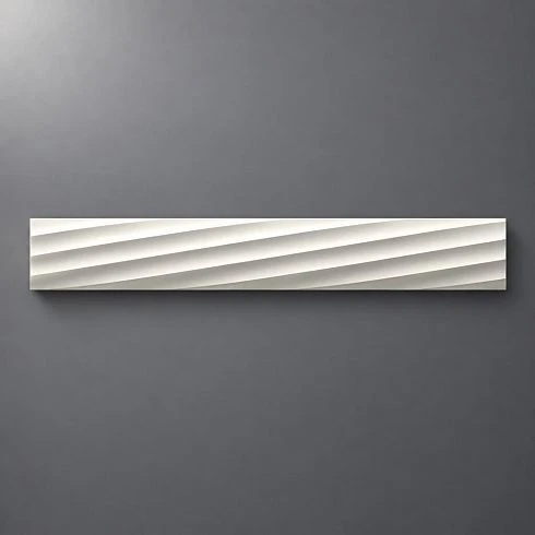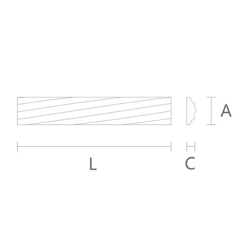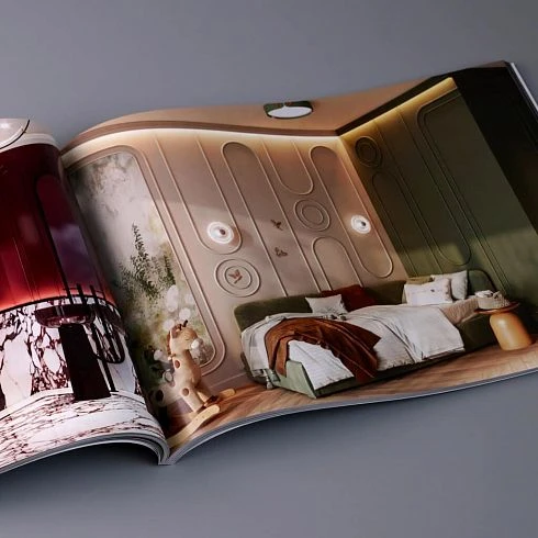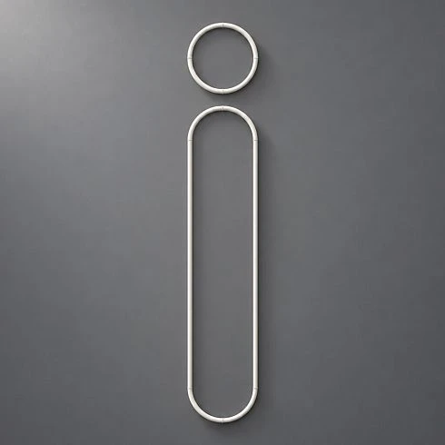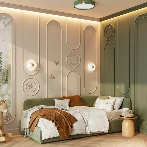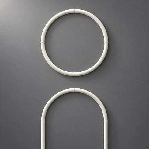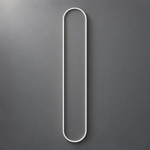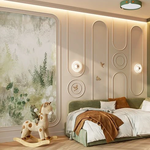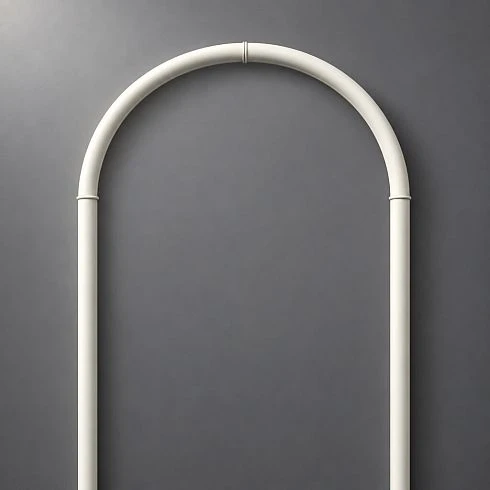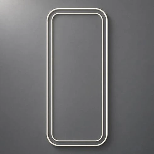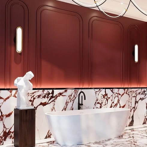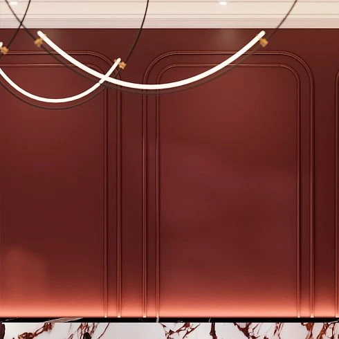
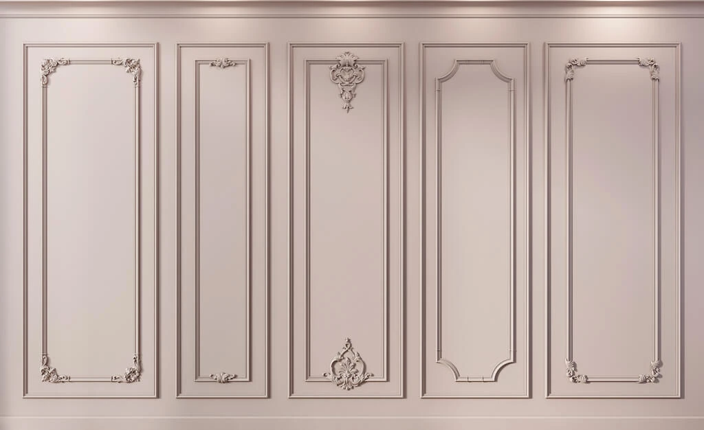
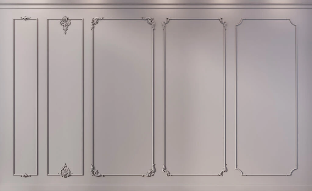
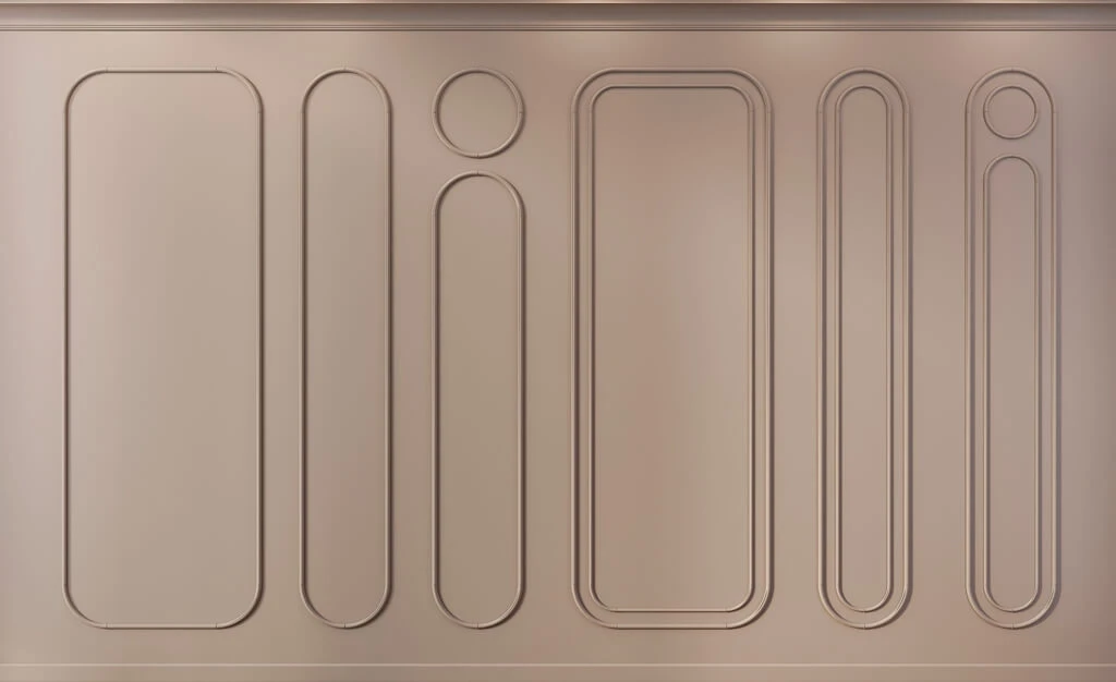
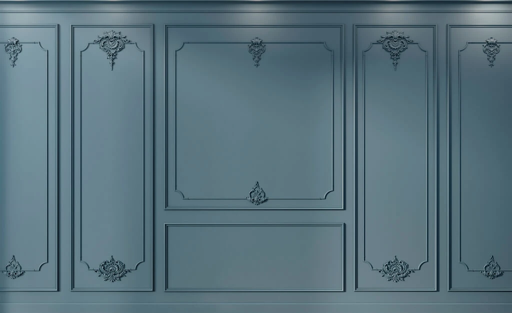
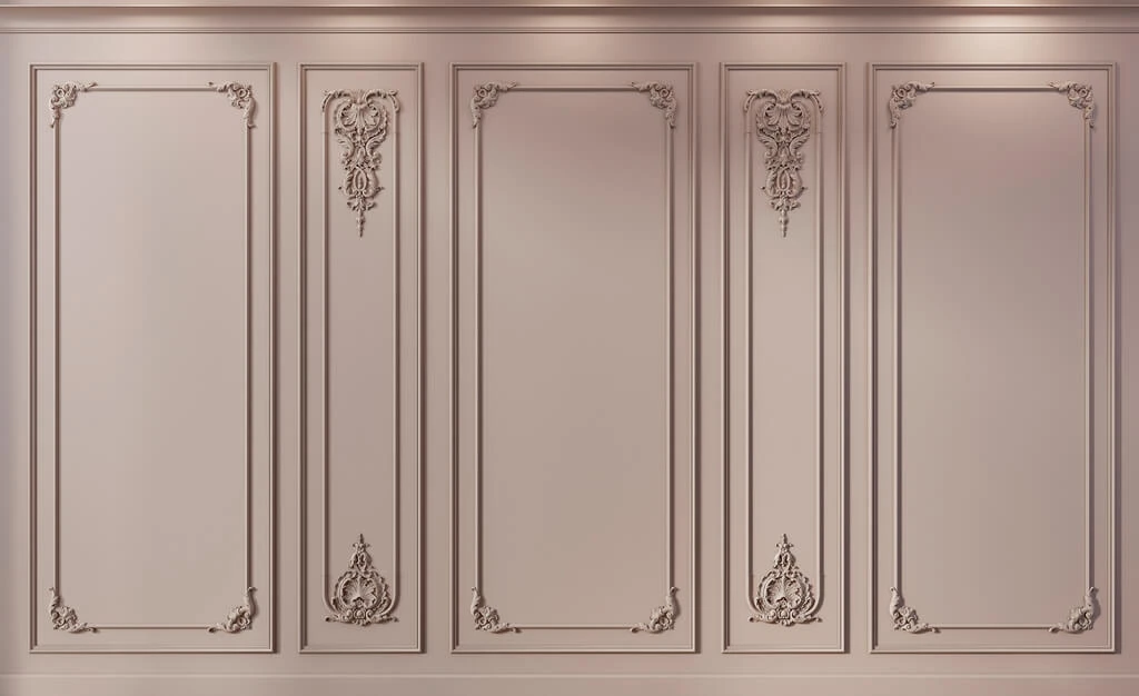
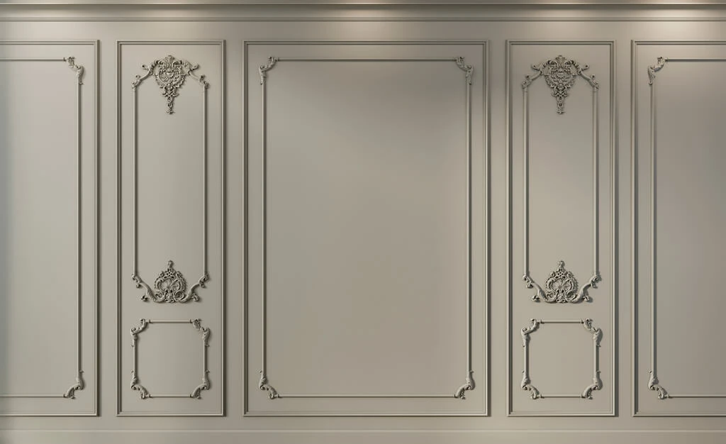
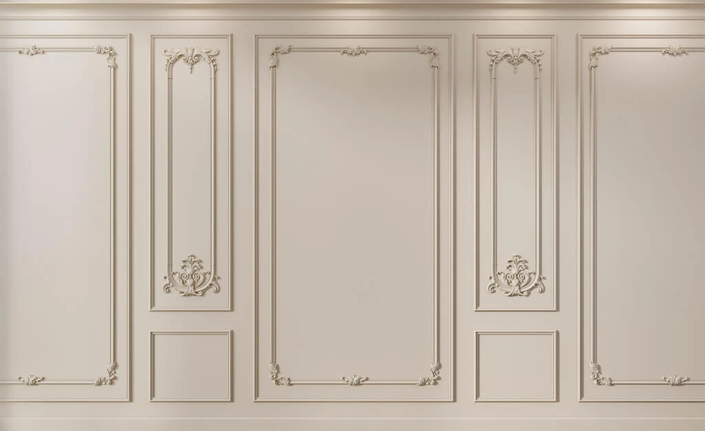
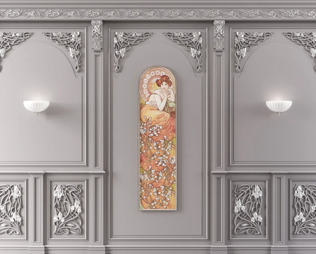
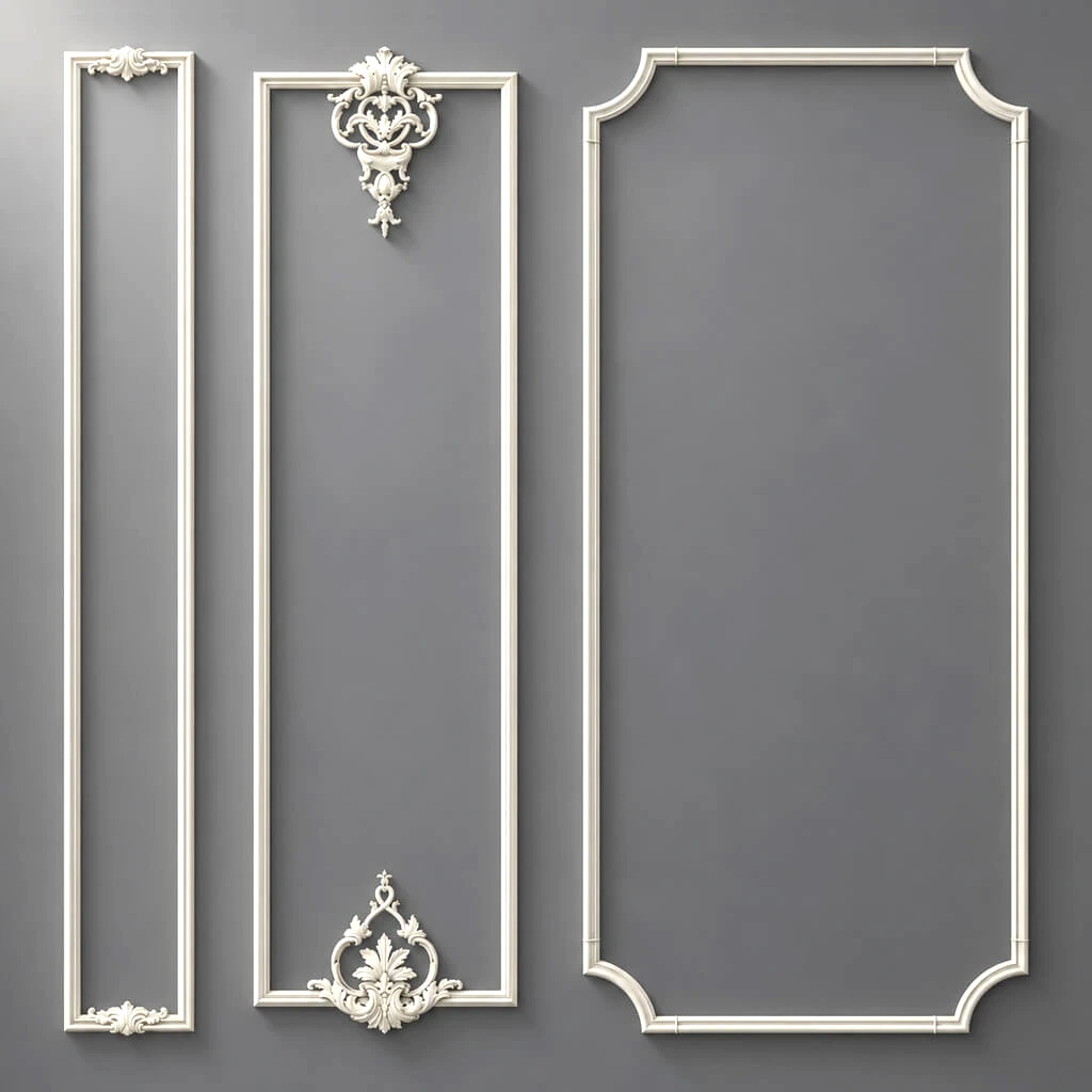
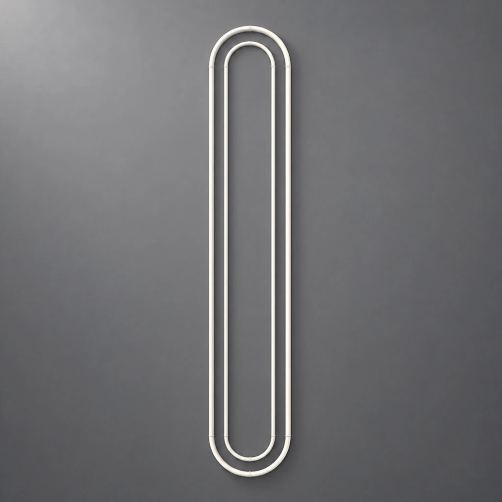
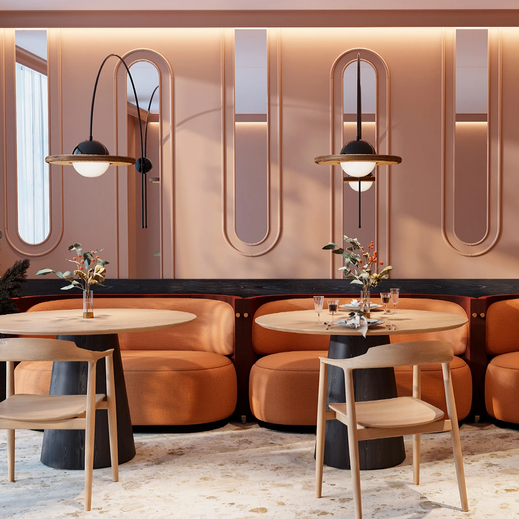
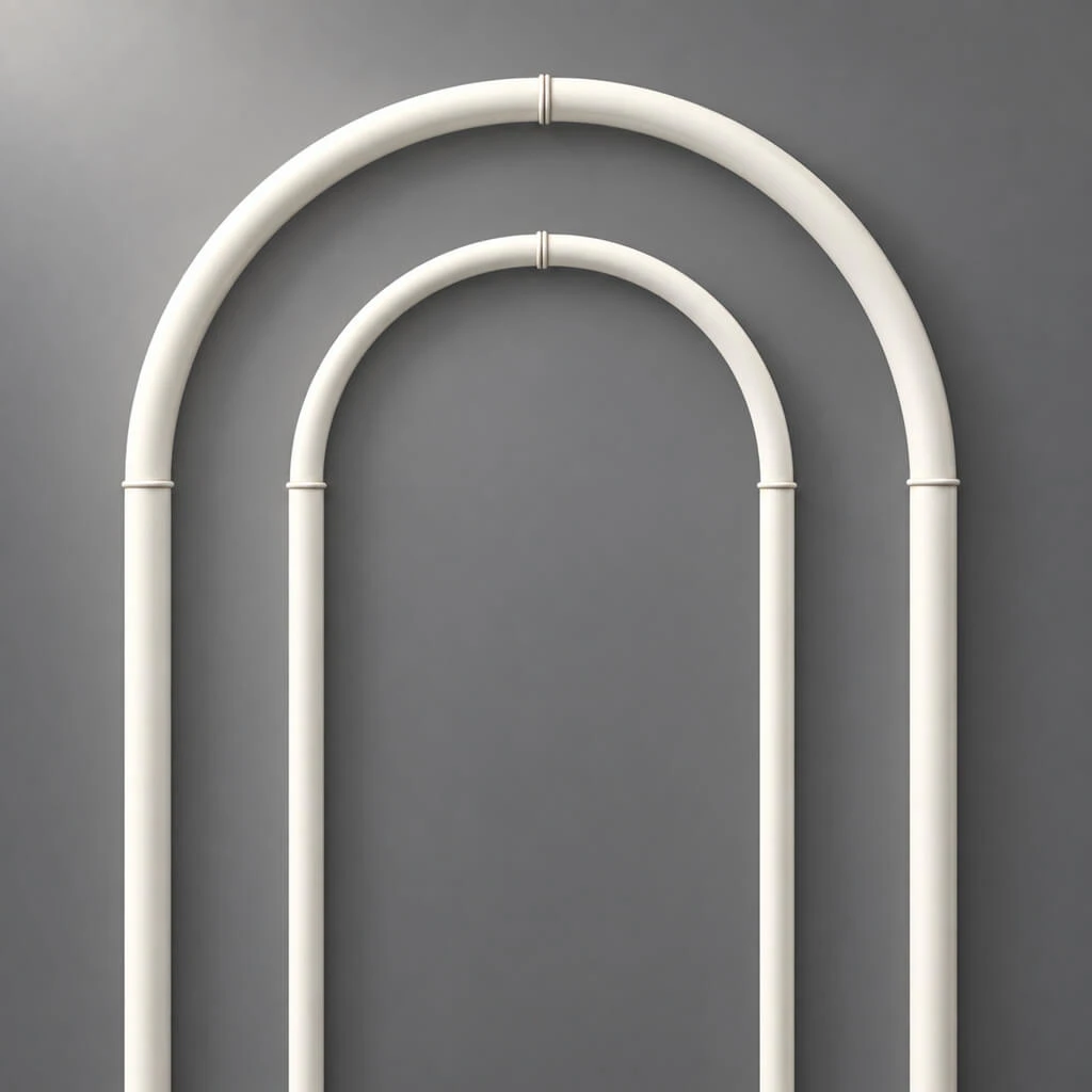



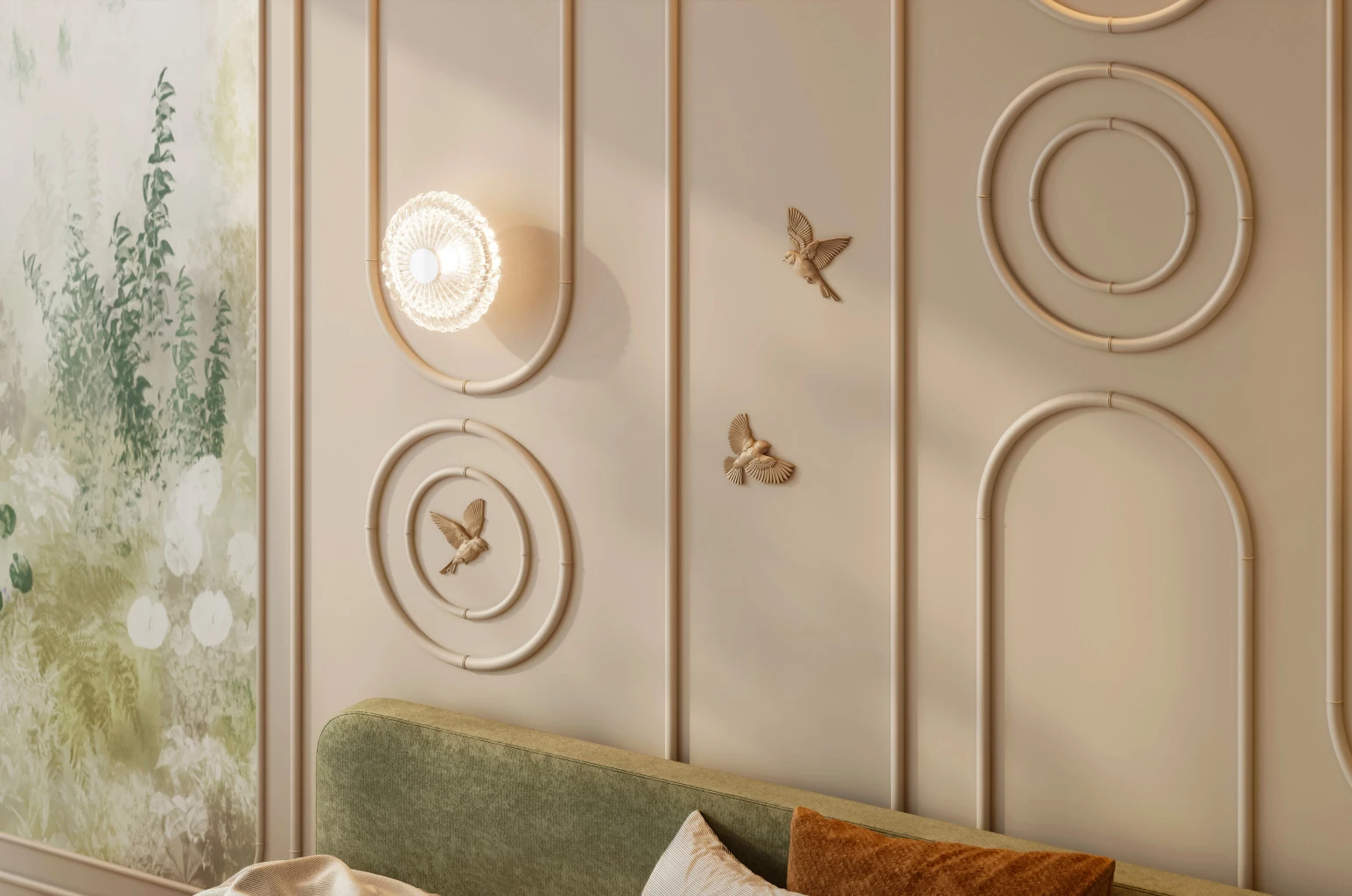
The arched shape makes the narrow vertical composition softer and more expressive while preserving the minimalist character of Japandi. A slim molding draws the wall upward, and the geometrically clean curves create a calm rhythm without ornamental overload. This format is especially suitable for a wall pier or repeated vertical decor.
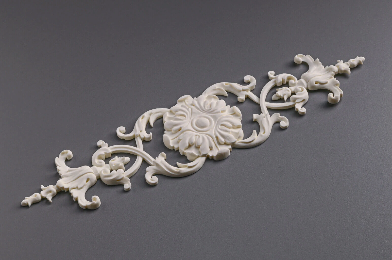
A ready-made set of stucco wall decor already unites coordinated elements into a single frame. It can be used on its own, repeated in a rhythm, or combined with other CPU pieces from the Japandi collection. For a custom layout, the collection's elements can be selected separately and assembled into a composition for a specific wall.
We have been on the market for over 20 years and are ready to offer you the best combination of aesthetics, quality, and practicality. Our polyurethane is not just a material, but a reliable foundation for flawless details, resistance to moisture and cracks, as well as convenient and quick installation. The company's success began in 2002, when two artists – Andrey Ragozin and Evgeny Tsapko – created a small creative workshop for making carved wooden products. The work of the craftsmen was quickly noticed, and within a year they were invited to participate in the reconstruction of the Konstantinovsky Palace in Strelna.
Every product in our range is the result of years of experience, thoughtful technology, and attention to detail. We constantly update our collections, follow and shape trends in interior design ourselves. From elegant neoclassicism to bold Art Deco, you will find the perfect accent for the interior of your dreams.
Choose durable polyurethane decor STAVROS — beauty proven by time and real projects, not just words.
We save your time, peace of mind, and budget
We solve your tasks with maximum speed
Streamlined process reduces all risks
Quality service regardless of order volume
Reliable partner — the foundation of your business
Our showrooms are located in Saint Petersburg and Moscow. Production is located in Saint Petersburg.
Moscow contacts: /contacts_all/
Contacts of Saint Petersburg: /contacts_all/
Send us the product codes, quantities and delivery destination. Contact our team to confirm availability and order details.
Please contact us to confirm shipping availability, costs and delivery times for your destination.
Delivery cost depends on the size, weight of the item, and delivery address.
Please ask our team to confirm shipping costs and delivery arrangements for your destination before placing an order.
Prices and availability of items on the website are always current. Data is updated daily.
Note: items in stock are stored on the warehouse in unpolished form and shipped within 3 working days.
If the item is not in stock, average production time: 5–10 working days.
This is the quality of polishing of the items.
Standard — machine polishing, at a more attractive price.
Prestige — detailed hand polishing, items do not require further work.
More details: /information/kachestvo/
This is the type of veneer of the items.
Under enamel: produced by gluing wooden laminates without color and texture matching. Contrast tonal and textural differences are noticeable. This blank should be chosen if the item is intended for opaque coating.
Under tinting: produced by gluing wooden laminates with color and texture matching. Tonal and textural differences may occur. This blank should be chosen if the item is intended for semi-transparent finish.
More details: /information/kachestvo/
Beech — dense, non-porous wood, most often used for items covered with enamel.
Oak — dense, porous wood with clearly visible natural grain. Due to its strength and decorative properties, it is often used in items with semi-transparent coating, highlighting the wood pattern.
Custom-made, if non-standard items are required, we can produce products from other types of wood, including blanks provided by the customer, manufactured according to our technical specifications.
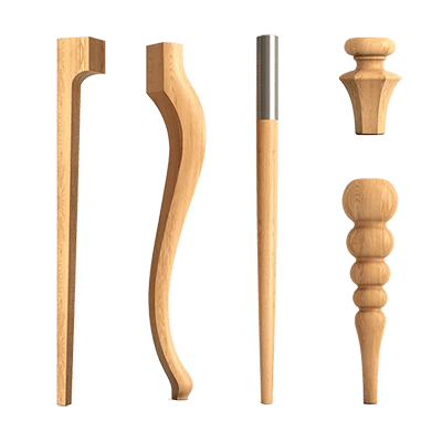
All our furniture legs can withstand a vertical load of at least 100 kg.
Average production time for custom-made items: 5–10 working days.
Most items are stored on the warehouse in unpolished form. We need time to polish and pack orders.
Yes, we manufacture non-standard items according to individual projects, but we only accept orders with a minimum quantity.
We can manufacture items of the desired size, but we only work with bulk orders. For details, please consult the sales department manager.
Yes, some of our products can be used outdoors. For example, polyurethane items, as well as carved door casings made of pine.
Other items are produced to order using PUR glue, if minimum quantity is available. No warranty is provided for such products, as outdoor conditions are considered aggressive.
Please contact our team to confirm available finishes, minimum quantities and a quotation for your order.
More details: /information/sovety/
Apply adhesive to the decor. Place it on the surface and press briefly. Then, lift the decor from the surface and leave it open for 3–5 minutes. Press the decor firmly onto the surface and hold for 5–10 seconds.
More details: /information/sovety/
Ideally, you should prepare a design project before placing an order.
You can do this yourself by downloading drawings of our products from our website, or you can order a project from us.
If the number of decorative elements and fittings is small, our company's manager can assist you with selection.
Unfortunately, this service is not provided.
The packaging method depends on the type of items, but in each case, we ensure sufficient protection for safe transportation.
We most often use corrugated cardboard and stretch film. Fragile items are additionally secured on a rigid base to prevent damage during transport.
Please confirm the minimum order quantity for your selected products and finishes with our team.
Please contact our team to discuss measurement and installation requirements for your project and destination before ordering.
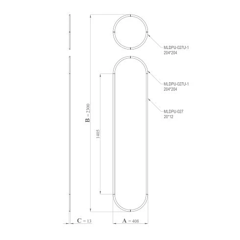
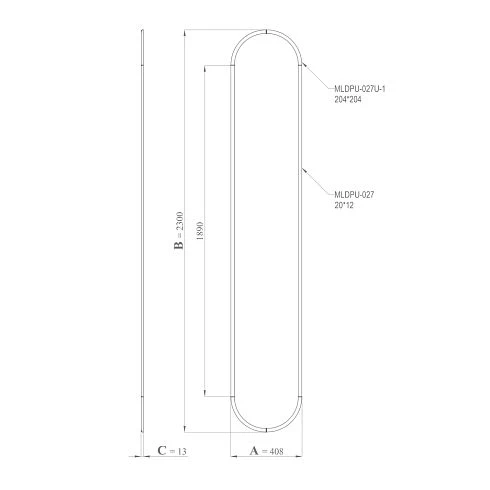
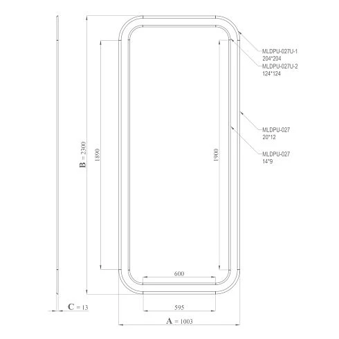
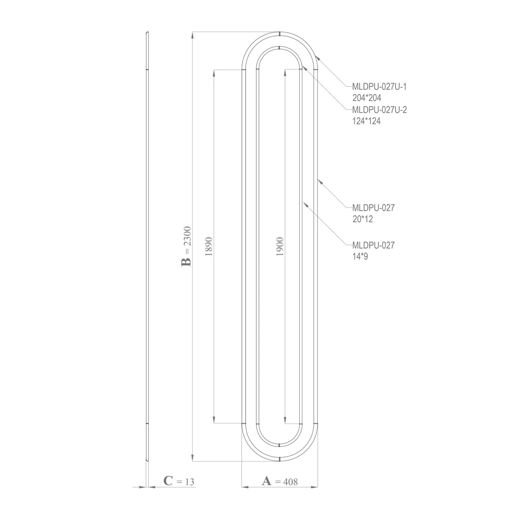
CPU-3-4 is a narrow polyurethane wall molding composition from the STAVROS Japandi Collection. Its reference layout measures 408 × 2300 × 13 mm (16.06 × 90.55 × 0.51 inches), making it an option to consider when a tall decorative accent must fit into a comparatively slim area of wall. The design brings together two scales of curved corner detailing and two sizes of the MLDPU-027 half-round molding. Rather than treating the wall as a surface that needs a bulky panel, the arrangement uses raised architectural lines to define a quiet, vertical feature.
That combination matters. CPU-3-4 is not simply a length of trim, a solid wall panel, or a copy of the wider CPU-3-3 frame. It is a reference configuration whose selected component sizes must be kept together when adapting the design. The large MLDPU-027U-1 corner works with the 20 × 12 mm straight profile; the smaller MLDPU-027U-2 works with the 14 × 9 mm profile. Checking those pairings is as important as choosing the overall look.
The dimensions below identify the manufacturer's referenced composition and its listed component variants. Measurements for the decorative corner pieces come from their individual drawings; they should not be mistaken for the outer width and height of the finished wall arrangement.
| Part or dimension | Manufacturer specification | What it means for your project |
|---|---|---|
| CPU-3-4 reference layout | 408 × 2300 × 13 mm | 16.06 × 90.55 × 0.51 in; narrow, tall proposed arrangement |
| MLDPU-027U-1 corner | A 204, B 204, C 13, D 23, L 287 mm | Larger curved ornament; use with the 20 × 12 mm molding |
| MLDPU-027U-2 corner | A 124, B 124, C 10, D 17, L 174 mm | Smaller curved ornament; use with the 14 × 9 mm molding |
| MLDPU-027, wider variant | 20 × 12 × 2600 mm | Straight half-round polyurethane molding for U-1 |
| MLDPU-027, finer variant | 14 × 9 × 2600 mm | Straight half-round polyurethane molding for U-2 |
| Component material | Polyurethane | Both straight profiles and the two listed corner elements |
The stock molding length is 2600 mm, about 102.36 inches. The reference composition height is 2300 mm, about 90.55 inches. These numbers describe different things: one is the supplied length of an individual straight profile, while the other is the overall proposed height of the wall design. A cutting plan is still needed, particularly when more than one profile size is used.
Before placing an order, compare the live product composition and dimensional drawing with the particular wall where CPU-3-4 will be installed. The public product table lists the four component types, but the number of each component supplied in a selected order should be confirmed in the live configuration rather than inferred from a narrative description.
A 408 mm overall width—just over sixteen inches—creates a very different visual effect from a broad picture frame molding layout. A narrow outline can give an uninterrupted section of wall a clear architectural rhythm without drawing attention away from a nearby doorway, artwork, or furniture. In a room with several openings, the available wall area can be more important than the total wall length. A compact upright composition makes it possible to study those smaller fields individually.
The reference width does not mean that any clear space of exactly 408 mm will automatically accommodate the design. Adjacent casings, wall corners, outlet plates, furniture, and the decorative element's actual junction points require allowance. Make a full-scale paper layout and examine it at normal viewing distance.
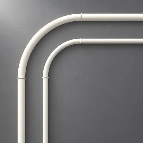
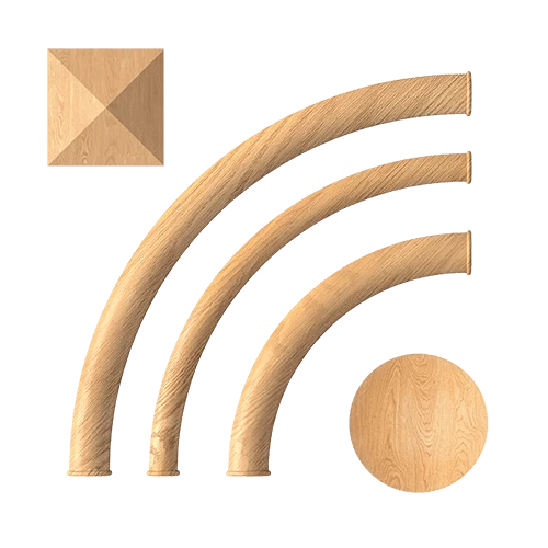
The set brings together the larger MLDPU-027U-1 curved detail and the smaller MLDPU-027U-2 detail. Their different A and B dimensions introduce variation within the same rounded design language. A large accent can establish the leading contour while a smaller one can support a secondary line. The exact placement and number of visible curved turns should be read from the CPU-3-4 drawing rather than invented from a product photo.
This is a measured form of ornament: the sculpted line can have character without floral carving or large classical rosettes. When both curves are painted to match the wall, their proportions become more noticeable through shadows than through strong color contrast.
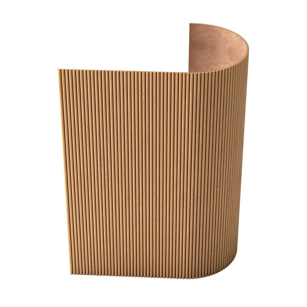
Decorative wall molding creates a raised outline or arrangement on a prepared background. The manufacturer lists polyurethane molding profiles and corner elements—not a rigid, full-surface board sized to 408 × 2300 mm. The area within an outline remains part of the existing wall unless a separate finish or panel material is deliberately specified.
This difference matters for both design and purchasing. Wallpaper, colored paint, decorative plaster, or another approved wall finish can change the appearance inside the frame, but these finishes are separate design decisions. The molding kit alone should not be presented as acoustic paneling, structural wall cladding, or a ready-to-install solid board.
The larger selected corner element is MLDPU-027U-1, A = 204 mm and B = 204 mm. Its additional drawing dimensions are C = 13 mm, D = 23 mm, and L = 287 mm. For a continuous profile junction, the manufacturer identifies the corresponding straight piece as MLDPU-027, 20 × 12 × 2600 mm. This is the wider of the two listed straight molding variants.
The 20 mm figure identifies the face width of that straight molding option and 12 mm its listed thickness in the product table. The corner's C and D dimensions come from a different drawing; comparing those numbers directly to 20 and 12 does not establish compatibility. Use the manufacturer-specified pair, then inspect the actual joint during dry fitting.
The more compact selected detail is MLDPU-027U-2, A = 124 mm and B = 124 mm, with C = 10 mm, D = 17 mm, and L = 174 mm. It belongs with the thinner MLDPU-027, 14 × 9 × 2600 mm profile. Its narrower face and lower listed projection help provide a calmer secondary line.
The part number MLDPU-027 appears on both straight products. That common designation does not make the two profile cross-sections interchangeable. The full cross-section must be written on the order and on the cut schedule. The U-1 and U-2 corner codes identify different parts, not a generic universal corner sold in two arbitrary sizes.
A 14 × 9 mm straight section placed directly against a U-1 corner may leave a visible step, even if its overall length is correct. Similarly, a 20 × 12 mm piece may be too broad for the U-2 transition. Filling the mismatch with adhesive or paint will not recreate the intended continuous profile. STAVROS documents the two pairings in its MLDPU-027 corner-to-molding compatibility guide.
When checking a purchase specification, list all four entries separately: U-1, U-2, MLDPU-027 20 × 12, and MLDPU-027 14 × 9. Include the length and the selected corner dimensions. For a project using both systems in one design, never combine their stock lengths into a single undifferentiated quantity.
Measure from the finished floor and finished baseboard up to the ceiling and any crown or ceiling trim. Mark nearby door casing edges, switches, outlets, wall sconces, vents, and furniture. The reference 2300 mm height is approximately seven feet six and one-half inches, but it is not a universal ceiling-height recommendation. Above and below the proposed molding, retain margins that work with the architecture of the actual room.
For a narrow wall between two openings, measure the clear field at several heights. Walls and casings are not always perfectly parallel. Select the narrowest relevant measurement, allow a reasonable visual margin, and verify that the curved elements do not intrude into the adjoining trim.
The dimensions A and B describe the corner element as shown in its technical drawing; they are not necessarily interchangeable with the length occupied along any imagined frame centerline. It would be unsafe to estimate the straight pieces by simply subtracting 204 mm twice from the overall width. The larger and smaller corner systems could also follow different paths within the reference layout.
Transfer the actual junction points from the drawing onto a scaled wall elevation. Mark where each straight segment begins and ends. From those points, record the required finished lengths separately for the 20 × 12 and 14 × 9 mm profiles. This is especially useful for CPU-3-4 because the relatively narrow overall footprint leaves less tolerance for guesswork.
Painter's tape, kraft paper, or removable templates can show the outer dimensions and approximate corner outlines. View the mockup from the doorway, the primary seating area, and the far end of a hallway. An accent that feels elegant up close may look crowded when repeated on multiple short wall sections; a slightly smaller detail can sometimes improve the balance.
Do not assume the mockup proves that a particular cut will fit. It tests placement and visual proportion. The technical drawing and a dry assembly of the real components confirm the junction geometry.
A hallway may have several doors, small clear sections, and limited room for freestanding furnishings. A narrow decorative wall molding treatment can introduce a recurring vertical rhythm without occupying floor space. CPU-3-4 may be explored as a feature on a clear wall segment, or as a reference when developing a coordinated series of accents. Consistent top and bottom alignment matters more than filling every section with identical decoration.
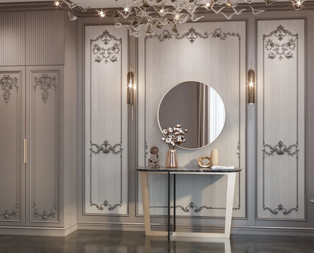
An entry wall is often seen from several angles in quick succession. A compact vertical design can act as a subtle companion to a narrow console, mirror, or small framed artwork. For this setting, keep enough open wall around the molding so the curves read clearly rather than merging into nearby trim. If an entry door swings toward the decorated surface, check all clearance requirements.
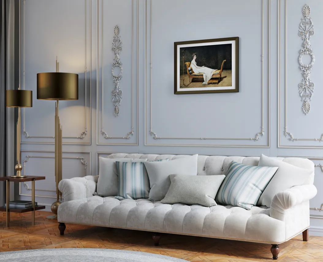
In an understated living room, a larger centerpiece such as a sofa or shelving system can dominate the main wall. A narrow polyurethane frame may therefore be better used on an adjacent side wall or on a carefully selected architectural pier. The soft half-round molding can connect the architectural outline to curved furniture edges and gentle lighting, without recreating a heavy traditional paneled room.
A bedside wall may have limited width after the headboard, nightstand, and lamp are positioned. A vertical accent can organize a clear strip of space if it does not collide with electrical fittings. In a dressing area, the composition can relate to mirror proportions or built-in cabinetry. The finish may be chosen to match the wall, keeping the decorative contour restful rather than highly contrasting.
A soft curved detail may be useful in studies, waiting areas, or other rooms that need architectural definition without ornate trim. Keep the design proportionate to the surface and coordinate it with door heights, shelving, and lighting. The set is decorative rather than structural, and should not be selected as a substitute for a protective corner guard or other functional building component.
Japandi interiors frequently combine warm restraint with controlled geometry. CPU-3-4 fits this direction through its half-round molding and curved accents rather than through an elaborate floral relief. It is not necessary to cover every wall with frames. A single carefully positioned reference composition can provide contrast against larger unornamented areas.
Balance can also come from coordinating the molding with the shapes of a side table, rounded mirror, or upholstered furniture. Where the room already contains strong patterns, keep the applied architectural outline simple.
Warm white, greige, stone, pale taupe, soft clay, and muted olive are possible finish directions, not factory color promises. Painting the molding and wall the same shade creates a soft shadow line. A two-tone treatment makes the frame more apparent and should be chosen with care, particularly where both the larger and smaller profiles appear in one arrangement.
Test the selected coating on compatible samples of the polyurethane surfaces and follow the paint manufacturer's preparation recommendations. The goal is an even, integrated appearance without obscuring the profile transitions with excess filler or thick paint.
Natural side lighting reveals curved relief through gradual shadows. A wall facing a window may make the outlines look stronger at some times of day than others. Directional sconces can highlight joints as well as the intended forms. Inspect the dry layout under the lighting that will actually be used, because imperfections in the curved-to-straight transitions can become conspicuous after a monochromatic finish.
Prepare one cutting schedule for MLDPU-027 20 × 12 × 2600 mm and another for MLDPU-027 14 × 9 × 2600 mm. Each should identify the intended position of the finished piece, its measured length, the end condition, and any allowance required by the installation method. This prevents a near-matching strip from being cut and installed at the wrong corner.
The 2600 mm stock length is useful for understanding joint planning, but it does not by itself tell you how many sticks are required. The number of segments, their exact endpoints, waste, the saw kerf, and any rejected or damaged pieces can affect material usage. The full kit quantity should be checked in the live order details and adjusted only through a verified specification.
A typical right-angle picture-frame molding arrangement can involve mitered straight profiles. CPU-3-4 includes shaped polyurethane corner elements, so a connection may follow a manufacturer-defined geometry rather than a plain 45-degree cut. Study the part drawing, confirm the intended meeting surfaces, and dry-fit one example of each corner-profile pair before cutting the full batch.
Keep cut components marked by size and location. Avoid touching up a mismatch by removing material from the face profile, because that can alter the shape along a line meant to continue smoothly from a molded corner.
For a run of several wall accents, calculate the first full composition, review its visual placement, and then create a schedule for the remaining wall fields. Measurements may vary around doors or along an older wall, so don't simply multiply one nominal length by the number of features. The outer dimensions of the reference kit are a starting point for design, not a substitute for a job-specific cutting plan.
Examine the existing surface for loose paint, unstable plaster, dust, grease, or uneven patches. A decorative molding system can only be as reliable as the underlying finish and the selected mounting method. A wall with significant irregularities may cause otherwise compatible components to sit at different elevations. Correct the surface condition using materials appropriate to that substrate before attempting the final dry fit.
Select an adhesive specifically compatible with polyurethane and the existing wall finish. Follow the adhesive manufacturer's requirements for preparation, application, holding method, cure time, and environmental conditions. Adhesives are not universally compatible with wallpaper, fresh paint, glossy coatings, or high-moisture environments; do not assume an item is included with the kit unless the live specification says so.
Where joints need filling, use an appropriate finishing compound and verify that it can be painted with the chosen coating. Keep filler work limited and neat so the distinctive half-round line retains its intended shape. The manufacturer drawing should remain the authority for orientation and part order.
Set out both sizes of corner element and their matching straight moldings on a clean surface. Check one U-1 to 20 × 12 connection and one U-2 to 14 × 9 connection, then mark all wall reference lines. Review symmetry, clearance, and spacing before the first permanent fixing. Do not rely on a verbal description of the finished frame when the drawing identifies specific component positions.
After installation, follow the relevant finishing system for joint preparation and painting. Do not announce that a particular adhesive will set in minutes or that the kit can be installed on every substrate without testing; those outcomes depend on the materials and conditions.
The CPU-3-2 narrow arched molding set also has a published reference width of 408 mm and a height of 2300 mm. Its itemized product list centers on MLDPU-027U-1 and the corresponding wider 20 × 12 mm MLDPU-027 profile. CPU-3-4 lists both U-1 and U-2 along with both straight profile sections. That makes component pairing and the detailed drawing particularly important for CPU-3-4.
The CPU-3-3 mixed-corner wall molding set has a published reference width of 1003 mm, or about 39.49 inches, rather than 408 mm. Both catalog compositions list the same four component types, but their reference proportions differ considerably. Do not copy a CPU-3-3 cut schedule or 1003 mm layout into a CPU-3-4 project.
The STAVROS Japandi Collection includes other rectangular and arched wall molding reference sets with varying visual scale. Select among them based on the dimensions of the clear wall field and the intended relationship with furniture. The Japandi wall-panel design idea INTPU-012 is also a useful source of general placement inspiration; individual component and material choices still need to be checked for the selected SKU.
The manufacturer lists a reference composition of 408 × 2300 × 13 mm, approximately 16.06 × 90.55 × 0.51 inches. Consult the actual technical drawing before translating this reference geometry into a particular wall's cut list.
The specified components in the CPU-3-4 product composition are polyurethane: both corner types and both MLDPU-027 straight molding variants. This differs from STAVROS sets that combine primed MDF with polyurethane ornament.
Use MLDPU-027 with a 20 × 12 mm cross-section and 2600 mm stock length. Record the full dimensional modification, not just the shared family number 027.
Use MLDPU-027 with a 14 × 9 mm cross-section and 2600 mm stock length. It is the finer line of the two polyurethane profile systems listed for CPU-3-4.
The published reference width is the main immediate difference: CPU-3-4 is 408 mm, while CPU-3-3 is 1003 mm. Both list U-1, U-2 and both MLDPU-027 sizes, so the drawing and arrangement—not the component names alone—must guide product selection.
A tone-on-tone finish is a natural design option for discreet architectural relief. Use the polyurethane surface preparation and paint system recommended for the products and the conditions of the room; test the selected color and sheen before completing the visible installation.
The answer depends on the actual order configuration, cut schedule, and whether the reference design is adapted. Because the two profile sizes are not interchangeable, calculate each type separately and confirm the quantities supplied in the selected kit.
Do not assume that a decorative component's polyurethane material makes the entire installation suitable for continuous moisture. Confirm the manufacturer's intended use, substrate, adhesive and finishing system for the specific location.
Do not assume that installation consumables are included. Check the active product listing or supplier quotation for the exact parts and any additional materials required.
A repeated arrangement may be designed if each wall field offers sufficient clearance and the horizontal and vertical alignment is considered. Prepare a layout for the full hallway, then measure each section individually before cutting.
CPU-3-4 offers a distinctive combination: a tall, narrow 408 mm reference format, rounded polyurethane decorative corners in two scales, and straight half-round moldings in corresponding 20 × 12 mm and 14 × 9 mm cross-sections. The most useful starting point is not a broad promise about minimalist design, but a precise match between the wall space, component drawings, and the two compatible profile systems.
Review the MLDPU-027 polyurethane molding options alongside the selected corner drawings. Confirm exact quantities and placement with the current product specification, dry-fit the joints, and finish the composition in a color and sheen suited to your interior. The result can be a calm architectural accent with deliberate proportions instead of another generic decorative wall treatment.
Our manager will contact you within 5 minutes