

Article Contents:
- The basket looks correct until we compare the cross-section
- Which pair is actually compatible
- Why trimming won't fix the mismatch
- Why the error becomes more noticeable after painting
- Size 84 × 84 mm
- Size 124 × 124 mm
- Size 164 × 164 mm
- Size 204 × 204 mm
- A and B do not replace the external layout
- C and D are not chosen instead of the straight molding size
- L helps understand the development of the decorative line
- Where to check the technical scheme
- Full order line
- Why the length of 2600 mm affects the number of joints
- One article number — two product modifications
- U-1 and U-2 are not size designations of one angle
- Why "almost matched" is not enough
- Four contours to draw
- Proportion of angle to straight side
- Equal angles in one frame
- Equal frames in one room
- Start with the canvas work area
- 84 mm angle on the door
- Angle 124 mm
- Angle 164 mm
- Angle 204 mm
- Handle check
- Ready idea CPU-3.1
- First, the furniture plan
- Side lighting enhances the relief
- One large frame
- A series of small frames
- Double outline
- What to measure
- Check when opening
- Size 84 mm
- Size 124 mm
- Sizes 164 and 204 mm
- Base and glue
- Formula
- Four corners per one frame
- Eight corners per two frames
- Is a spare corner needed
- Basic principle
- Formula after reading the drawing
- Why measuring with installed templates is more reliable
- Theoretical minimum
- Actual quantity
- Example of a simple map
- Example where the sum deceives
- Cut
- Technological allowance
- Straight horizontal parts
- Straight vertical parts
- Total length
- Cutting map
- One frame
- Two frames
- Short insert looks random
- Specific mounting adhesive
- What needs to be laid out
- What is being checked
- Check on a horizontal surface
- Check directly on the surface
- What counts as a completeness defect
- Define the baseline lines
- Check the diagonals
- Start with the four corners
- Do not mark each side independently
- Uneven wall
- Painted door
- Furniture front
- Old stucco molding
- Numbering
- Sequence
- Check before the final cut
- Joint of two straight planks
- Possible sequence
- Do not use glue as putty
- The joint must continue the profile
- One material does not guarantee one shade without a common technology
- Paint before or after installation
- Side lighting
- Frame color
- Corner article number
- Angle size
- Straight molding article number
- Straight molding cross-section
- Length of the strip
- Error 1. Rely only on the number 027
- Error 2. Order MLDPU-027 14 × 9 mm for U-1
- Error 3. Consider U-1 and U-2 as different sizes of the same part
- Error 4. Choose the angle from a photo
- Error 5. Order one sample and mentally multiply the impression by four
- Error 6. Use A instead of the occupied length without a drawing
- Error 7. Compare C × D with 20 × 12 arithmetically
- Error 8. Calculate the perimeter without subtracting corners
- Error 9. Divide the total footage by 2600 without a map
- Error 10. Ignore the cut
- Error 11. Use a universal ten percent
- Error 12. Order four planks for four sides
- Error 13. Save on the long side with a joint
- Error 14. Buy one corner per frame
- Error 15. Count doors instead of frames
- Error 16. Mix sizes 124 and 164 mm
- Error 17. Choose 204 mm for a small facade
- Error 18. Not account for the door handle
- Error 19. Not open the door with the mockup
- Error 20. Glue without dry assembly
- Error 21. Use glue to compensate for the step
- Error 22. Not check the base
- Error 23. Paint parts separately without a sample
- Error 24. Paint before checking dimensions
- Error 25. Not labeling cut parts
- Error 26. Losing leftovers
- Error 27. Choosing glue by name
- Error 28. Ordering decor and forgetting the straight profile
- Error 29. Ordering profile and forgetting corners
- Error 30. Starting installation without final invoice
- Corner Elements
- Straight molding
- Dry joint
- Installation materials
- Documents
- Which molding is compatible with MLDPU-027U-1?
- Will MLDPU-027 with dimensions 14 × 9 mm fit?
- Why do both profiles have the same article number MLDPU-027?
- Is it enough to write "MLDPU-027"?
- What sizes are available for MLDPU-027U-1?
- What do C and D mean?
- Why is C × D not equal to 20 × 12 mm?
- What does L mean?
- Which angle should be chosen for the door?
- Is 84 mm suitable for any door?
- When should 204 mm be chosen?
- How many angles are needed for one frame?
- How many angles are needed for two frames?
- Can three angles be ordered?
- Is a spare angle needed?
- How to calculate straight molding?
- Can it be calculated by perimeter?
- What is the length of one plank?
- How to convert meters into planks?
- Why can the cutting map increase the quantity?
- Do I need to account for the saw kerf?
- What percentage of extra should I add?
- Can I join two short pieces on the visible side?
- Can leftovers be used?
- Can I trim the corner piece itself?
- Can I mix 84 and 124 mm corners?
- Can I use U-1 on top and U-2 on the bottom?
- Can I paint the corners and molding in the wall color?
- Can I make them contrasting?
- Paint before or after gluing?
- What glue is needed?
- Will wood glue work?
- Can it be glued onto wallpaper?
- Can it be installed on a painted wall?
- Can it be installed on an MDF door?
- Is it suitable for a kitchen cabinet front?
- Can it be used on the ceiling?
- How to check compatibility before ordering?
- What to do if a 14 × 9 mm profile has already been purchased?
- What to do if the corners are already glued?
- What to do if the straight section turned out negative?
- What to do if 20 mm remains between the corners?
- What to do if one side is longer than 2600 mm?
- Where is the best place to position the joint?
- Do I need to order the molding in one batch?
- How to store 2600 mm strips?
- Can the strips be transported in a passenger car?
- How to check the size upon delivery?
- Where can I see the current price for MLDPU-027U-1?
- Is the price the same for all sizes?
- Where can I buy decor for moldings?
- Where to buy wall molding for decoration?
- What is included in a full order?
- Is a ready-made set needed?
- Can I order one corner as a sample?
- Do I need to order a strip for a sample?
- What is the main question to ask the manager?
- What question should be asked to the installer?
- What question to ask a designer?
- What question should I ask myself?
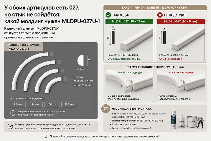
There are two products with the same number 027 in the cart. The first is the corner element MLDPU-027U-1. The second is the straight molding MLDPU-027. The names look consistent, the material is the same, the pattern is similar, the series matches. It seems you can choose any available size of the linear profile: 14 × 9 or 20 × 12 mm. What difference does it make if the article numbers belong to the same system?
The difference is discovered not on the screen, but during dry assembly. The corner turns out to be more massive than the straight strip, the relief does not continue the line, the transition height changes, and instead of a solid frame, a visible step is obtained. Trimming does not help: the mismatch is not in the length, but in the cross-section. The buyer chose the correct decorative corner, but placed an unsuitable straight profile next to it.
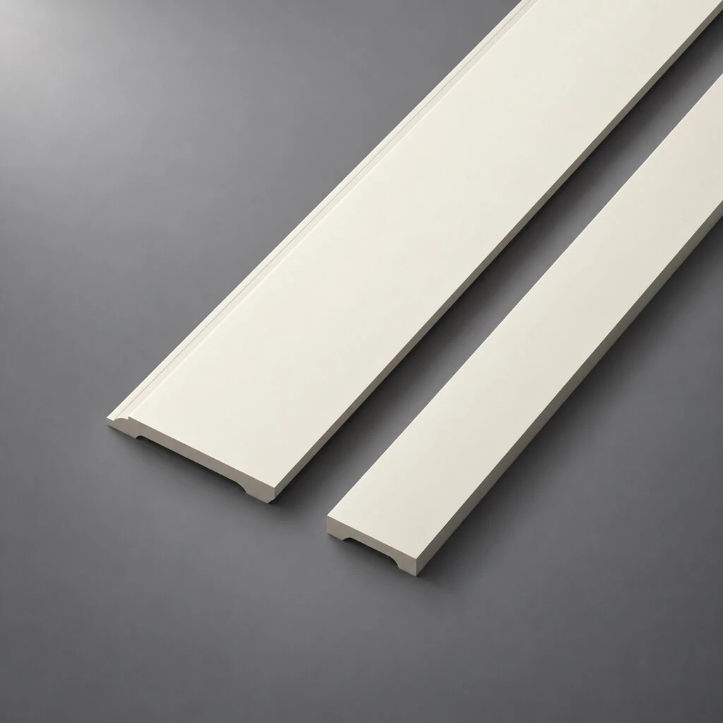
For MLDPU-027U-1, you need the molding MLDPU-027 with dimensions 20 × 12 × 2600 mm. The variant MLDPU-027 with dimensions 14 × 9 × 2600 mm belongs to a thinner system and is combined with MLDPU-027U-2. The matching number 027 helps determine the family, but does not cancel the check of the full article number, the U-1 or U-2 index, and the size line of the straight molding.
This is exactly where you need to start the order. Not with the color of the future wall, not with the number of frames, and not even with the choice of a large or small corner. First, a compatible pair is fixed:
MLDPU-027U-1 + MLDPU-027 20 × 12 × 2600 mm.
Only after this, one of the four sizes of the corner element is selected, the corners to be decorated are counted, the straight sections between the decors are measured, a cutting map for strips 2600 mm long is drawn up, a justified allowance is added, and mounting materials are selected. This order protects against the most expensive mistake: all items have arrived, the quantity is correct, but they cannot be assembled into a single line.
If the task has already been measured and the system is confirmed, you can buy the corner element MLDPU-027U-1, choosing the version 84 × 84, 124 × 124, 164 × 164, or 204 × 204 mm. But the corner card is only the first half of the order. The second half is the compatible straight profile, the quantity of which is determined by the actual layout.
The main practical conclusion can be formulated right now:
The same number 027 in the article numbers does not mean that any MLDPU-027 will fit any corner of this series. For MLDPU-027U-1, order MLDPU-027 with a cross-section of 20 × 12 mm. The 14 × 9 mm profile is used with MLDPU-027U-2.
Then begins not theory about polyurethane molding, but normal work with the future frame: size, proportions, joints, cutting, quantity, and the complete set.
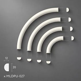
The cart looks correct until the cross-section is compared
An erroneous configuration rarely looks absurd. On the contrary, it seems very logical. The buyer sees:
-
MLDPU-027U-1;
-
MLDPU-027;
-
one material;
-
one series number;
-
same purpose;
-
the ability to decorate a door, wall, or furniture facade.
The problem lies hidden inside the linear molding card. MLDPU-027 is available in two cross-sections:
-
14 × 9 mm;
-
20 × 12 mm.
The length of both strips is 2600 mm. If you look only at the name, the two options are perceived as interchangeable scales of one profile. But the corner element must continue not the general mood of the pattern, but the exact line of the specific cross-section.
Which pair is truly compatible
| Corner element | Compatible linear profile | Result |
|---|---|---|
| MLDPU-027U-1 | MLDPU-027 20 × 12 × 2600 mm | A more pronounced system with a consistent transition |
| MLDPU-027U-2 | MLDPU-027 14 × 9 × 2600 mm | A thinner and lighter system |
| MLDPU-027U-1 | MLDPU-027 14 × 9 × 2600 mm | Incompatible cross-section combination |
| MLDPU-027U-2 | MLDPU-027 20 × 12 × 2600 mm | The straight profile will turn out larger than the intended angle |
The buyer can choose the correct molding number and still make a mistake if they do not specify 20 × 12 mm. Therefore, the entry “MLDPU-027 — 4 pcs.” is incomplete. The invoice must include the full dimension line.
The correct wording is:
Polyurethane molding MLDPU-027, cross-section 20 × 12 mm, length 2600 mm, quantity — according to the cutting plan.
Such an order can be checked before payment. If 14 × 9 mm appears in the invoice, the error is visible immediately, not after unpacking the corners.
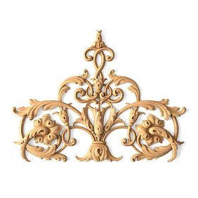
Our factory also produces:

Why trimming will not fix the mismatch
Length is adjusted by cutting. Cross-section is not.
You can shorten a 2600 mm strip to the required straight section. You can perform precise end cutting. You can adjust a small technological allowance. But you cannot turn a 14 × 9 mm profile into a 20 × 12 mm profile without changing its shape.
When there is a mismatch, several defects appear at once:
-
different relief height;
-
step at the transition;
-
uneven line width;
-
gap in light and shadow;
-
visible edge after painting;
-
difficulty filling the joint;
-
violation of symmetry of the entire frame.
A thick layer of glue doesn't help either. Glue connects parts to the base, but should not model the missing volume of the decorative profile.
Get Consultation
Why the error becomes more noticeable after painting
While the parts lie separately, a small difference seems insignificant. After installation, the frame becomes one continuous line. Side light emphasizes the relief, and monochrome painting unifies the surface while revealing any step.
The discrepancy is especially noticeable:
-
on a smooth wall;
-
under directed lighting;
-
on a dark color;
-
around a tall door;
-
in a symmetrical pair of frames;
-
on a facade viewed from a close distance;
-
in a minimalist interior with few distracting details.
Saving on the correct cross-section turns into a permanent visual defect. Therefore, compatibility is checked before calculating the quantity.
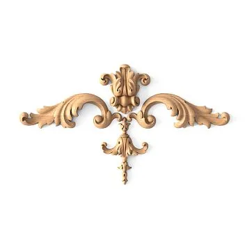
MLDPU-027U-1: four sizes of one corner element
MLDPU-027U-1 is available in four versions. They differ in the angle size and the length of the decorative line, but maintain constant values of C = 13 mm and D = 23 mm.
| A × B, mm | C, mm | D, mm | L, mm | Visual scale |
|---|---|---|---|---|
| 84 × 84 | 13 | 23 | 117 | Compact |
| 124 × 124 | 13 | 23 | 174 | Medium |
| 164 × 164 | 13 | 23 | 231 | Large |
| 204 × 204 | 13 | 23 | 287 | Maximum in the line |
These versions do not change the compatible linear molding. For each MLDPU-027U-1, an MLDPU-027 of 20 × 12 mm is still required. The size of the corner decorative element is chosen based on the composition, while the cross-section of the straight profile is determined by system compatibility.
These are two different tasks:
-
What angle scale fits the frame?
-
Which profile continues its line without a step?
The answer to the first question can be 84, 124, 164, or 204 mm. The answer to the second remains unchanged: 20 × 12 mm.
Size 84 × 84 mm
The most compact version is suitable for small compositions where a large decorative turn would take up too much space. It can be considered for:
-
a narrow door frame;
-
a small furniture front;
-
a compact wall panel;
-
an inset frame within a larger composition;
-
an area with limited distances to the edge;
-
calm decor without heavy corner accents.
But the word "compact" does not mean "inconspicuous." The decorative line has a pronounced profile corresponding to MLDPU-027 20 × 12 mm. Even a small corner requires sufficient space and careful centering.
Before ordering, it is useful to cut out four paper squares of 84 × 84 mm and place them on the project surface. One sample in hand does not show the rhythm of the entire frame.
Size 124 × 124 mm
Medium execution increases the presence of corners, but does not yet turn them into a dominant part of the composition. It is considered for standard door leaves, medium-format wall frames, and furniture facades where a noticeable but not excessive decorative transition is required.
The difference between 84 and 124 mm is 40 mm on each side. On paper, the number seems small. In an assembled frame, four corners increase simultaneously, so the composition changes more significantly.
When choosing, you need to check:
-
distance to the edge of the door;
-
distance to the casing;
-
the width of the straight section;
-
handle position;
-
the adjacent frame;
-
the height of the plinth;
-
the free space inside the composition.
If after placing the corners the straight molding remains only as a short fragment, the size may be too large.
Size 164 × 164 mm
A large corner becomes an important part of the pattern. It is chosen not only for connecting straight slats, but also for the expressive shape at each vertex of the frame.
The 164 × 164 mm execution is suitable for larger walls, tall doors, and wide facade compositions. However, it requires long straight sections. If the frame is small, four large corners begin to crowd each other.
Useful check:
-
Mark the external size of the future frame.
-
Place a 164 × 164 mm template in each corner.
-
Connect them with strips of width matching the straight profile.
-
Assess the remaining length of the straight sections.
-
Look at the composition from the distance from which it will be perceived after installation.
The corner should complete the line, not absorb it.
Size 204 × 204 mm
The maximum version is designed for a large scale. It can work in a tall door composition, on a large wall, around a significant decorative field, or in a project where corners should become the main accents.
On a small facade, the 204 mm size can take up almost the entire side. Then MLDPU-027 between adjacent corners either turns into a short insert or stops fitting altogether.
The buyer must check not only the external dimensions of the surface, but also the free zone:
-
to the handle;
-
to the hinge;
-
to the edge of the facade;
-
to the adjacent profile;
-
to the switch;
-
to the socket;
-
to the door casing;
-
to the baseboard;
-
to the ceiling cornice;
-
to the furniture adjacent to the wall.
A large angle cannot be reduced after purchase without destroying proportions. If the layout does not fit, a smaller version is chosen.
A, B, C, D and L: how to read dimensions without improvisation
The size table looks simple, but the letters cannot be renamed by guesswork. The exact position of each line is shown in the drawing.
For four versions, the values are known:
-
A and B — 84, 124, 164 or 204 mm;
-
C — 13 mm;
-
D — 23 mm;
-
L — 117, 174, 231 or 287 mm.
The buyer may assume that C × D equals the cross-section of the corner element, and then compare 13 × 23 with the linear profile 20 × 12. The numbers do not match, and doubt arises: is this really one system?
They cannot be compared by direct arithmetic equality. The dimension lines of the corner piece and the straight molding may be oriented along different axes and describe different parts of the geometry. Compatibility is confirmed by the system card, not by rearranging numbers.
A and B do not replace the external layout
Since A and B are equal, the corner has a symmetrical dimension in two directions. But using 84, 124, 164, or 204 mm in the calculation of the straight section is only possible after understanding from which point to which point the dimension line is drawn.
You cannot automatically write:
length of straight section = frame width − 2 × A
without checking the drawing. Such a formula may be correct for a specific scheme if A indeed shows the occupied length along each side from the vertex. But the article should not present an assumption as a universal rule.
Correct sequence:
-
Open the drawing of the selected size.
-
Find the start and end of A and B.
-
Transfer these points to the layout.
-
Measure the free section between adjacent corners.
-
Only after this count MLDPU-027.
C and D are not chosen instead of the size of the straight molding
The compatible profile is already defined: 20 × 12 mm. No need to find a mathematical way to get these numbers from C = 13 and D = 23.
The erroneous logic looks like this:
-
at angle C = 13, so a molding around 14 mm is needed;
-
D = 23, so the 20 mm option almost matches;
-
you can take any.
The correct logic is different:
-
the corner element has its own drawing;
-
the linear molding has its own cross-section;
-
the catalog assigns MLDPU-027U-1 to MLDPU-027 20 × 12 mm;
-
dry assembly confirms the continuation of the relief.
L helps to understand the development of the decorative line
The value of L increases with the size of the angle:
-
117 mm;
-
174 mm;
-
231 mm;
-
287 mm.
The exact trajectory of line L should be viewed in the figure. It cannot be automatically considered a straight segment along the facade or a length to be subtracted from the perimeter.
This parameter is useful for comparing scales: the larger version has a more extended decorative contour. However, the calculation of the straight molding is still based on the actual points of contact.
Where to check the technical diagram
Before placing an order, open the product card and study the drawing of each version. If necessary, print the diagram to scale and compare it with the facade or wall.
The technical drawing answers questions that a photo does not show:
-
where the straight joint begins;
-
how the profile is oriented;
-
what part the corner occupies;
-
which side is the front side;
-
how the element is positioned in the left and right corner;
-
what size needs to be transferred to the surface.
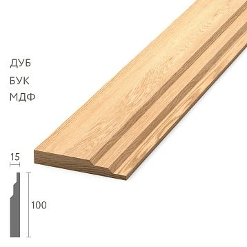
MLDPU-027 20 × 12 mm: straight profile that continues U-1
After selecting the corners, you need to buy molding MLDPU-027 20 × 12 mm. The length of one strip is 2600 mm.
The MLDPU-027 card includes two sections. Therefore, in the cart, it is not enough to see the correct article number. Check the specific modification.
Full order line
MLDPU-027, 20 × 12 × 2600 mm.
Here:
-
20 × 12 mm — cross-section;
-
2600 mm — length of one strip.
The quantity is specified in pieces, not just in linear meters. The buyer can calculate the total length of straight sections, but whole strips will need to be purchased.
Why the 2600 mm length affects the number of joints
A long straight section can exceed 2600 mm. Then a joint of two planks appears. Its position needs to be determined in advance.
You should not automatically place the joint in the middle of the most visible side. Sometimes it can be:
-
shifted to a less visible area;
-
positioned symmetrically;
-
linked to the architectural axis;
-
distributed among several frames;
-
eliminated by using a different cutting layout.
The exact solution depends on the dimensions of the composition and the surface requirements.
One article — two product modifications
MLDPU-027 shows why an article cannot be read without dimensions. If only the name is specified in the request, the supplier and the buyer may understand it differently.
Next to each line should be:
-
cross-section;
-
length;
-
quantity;
-
purpose in cutting.
For example:
| Position | Modification | Quantity | Purpose |
|---|---|---|---|
| MLDPU-027 | 20 × 12 × 2600 mm | 3 pcs. | Door frame D-01 |
| MLDPU-027 | 20 × 12 × 2600 mm | 4 pcs. | Two wall frames C-02 and C-03 |
Such a list is easy to check upon acceptance.
Why MLDPU-027 14 × 9 mm does not fit U-1
A thinner profile does not become a bad product. It simply belongs to a different system.
MLDPU-027 sized 14 × 9 mm should be considered together with MLDPU-027U-2. This pair creates a lighter line. The buyer chooses it when:
-
the frame is small;
-
a thin contour is required;
-
the large cross-section 20 × 12 mm seems heavy;
-
decorative corners U-1 take up too much space;
-
the facade has a small free field;
-
the composition should be calmer.
You can view the corner element MLDPU-027U-2 and compare the two systems before ordering.
U-1 and U-2 are not size designations for one corner
The index should not be perceived as a serial number of the package. It separates different compatible solutions.
| Criterion | System U-1 | System U-2 |
|---|---|---|
| Corner element | MLDPU-027U-1 | MLDPU-027U-2 |
| Linear profile | MLDPU-027 20 × 12 mm | MLDPU-027 14 × 9 mm |
| Line character | More pronounced | Thinner |
| Can they be mixed | No, without a special design solution | No, without a special design solution |
| Do I need to check the angle size | Yes | Yes |
| Is a dry assembly needed | Yes | Yes |
Mixing U-1 and U-2 in one frame is possible only as a deliberate authorial technique with a separate development of the transition. For standard configuration, such an experiment is not needed.
Why “almost matched” is not enough
In the decorative line, there is no useful concept of an “almost compatible profile.” If the relief differs by a few millimeters, the eye perceives a violation. The task of the system is precisely to avoid manual modeling of the transition.
When a standard neat result is needed, a confirmed pair is chosen.
The choice of corner size starts from the outer border of the frame.
The buyer often chooses the size of MLDPU-027U-1 based on the total area of the wall or door. This is not enough. The specific zone where the frame will pass is important.
On a door, not the entire panel is measured, but the free field between edges, handle, panel, glass, and other details. On a wall, furniture, sockets, switches, and neighboring frames are taken into account. On a furniture facade, hinges, gaps, milling, and the opening line are checked.
Four contours that need to be drawn
For an accurate selection, it is useful to mark four boundaries on the surface or plan:
-
outer frame size;
-
inner size;
-
zones occupied by corner elements;
-
straight sections of MLDPU-027.
If only the outer line is marked, the buyer does not see how much space will remain inside after installing large corners.
Proportion of the corner to the straight side
The corner should be perceived as a completion, and the straight molding as a connecting line. When decorative elements are too large, the frame breaks apart into four separate corners. When too small, they can get lost on a large wall.
For a preliminary assessment, compare:
-
size A/B;
-
length of the straight section;
-
total frame height;
-
total width;
-
viewing distance;
-
number of adjacent compositions.
There is no universal coefficient. A paper mockup is more reliable than a formula that does not account for the interior.
Identical corners in one frame
All four vertices of a rectangular composition are finished with one size, MLDPU-027U-1, unless the project specifies a different pattern. Mixing 84 and 124 mm will disrupt symmetry and change the lengths of straight sections.
The invoice specifies the full modification:
MLDPU-027U-1 164 × 164 mm — 4 pcs.
Identical frames in one room
If several identical frames are located on the wall, it is better to order the corner elements in one batch. This simplifies:
-
layout;
-
painting;
-
acceptance;
-
replacement;
-
symmetry control;
-
distribution of straight molding.
If the frames differ in size, it is not necessary to change the corners. One scale can tie the composition together, while the lengths of straight sections will vary.
Door: the corner must fit between the edge, handle, and facade pattern
Door decor with moldings is perceived from a close distance. Here, joints, uneven painting, and frame displacement are noticeable.
Start with the working area of the canvas
From the total door width, exclude:
-
required edge offset;
-
handle zone;
-
lock location;
-
glass insert;
-
existing panel;
-
ventilation grille;
-
other decorative elements.
The remaining field determines the maximum frame.
84 mm corner on the door
Compact execution allows preserving long straight sections even on a relatively narrow panel. It is suitable when the decor should be light or there are several frames.
Angle 124 mm
The medium format makes the corners more noticeable. On a standard door, it can be a good compromise between a thin line and decorative expressiveness, but the decision is verified with a mockup.
Angle 164 mm
The large size requires a tall or wide door. On a small panel, the inner field quickly decreases.
Angle 204 mm
This execution is suitable only with sufficient scale. Four elements occupy significant areas of the sides. Layout without a drawing is risky.
Handle check
Open the door and grasp the handle. The hand and fingers should not touch the molding. Measure not only the distance from the center of the hardware, but also the actual trajectory of the hand.
Ready idea CPU-3.1
To understand the proportions, you can look at the door design with moldings CPU-3.1. The ready solution helps to see how thin and more pronounced systems differ in composition.
But the photo cannot be copied without measurements. The size of a specific door, indents, and the number of parts are calculated anew.
Wall frame: consider furniture, light, and neighboring lines
The query "where to buy moldings for wall decor" arises when the overall composition is already conceived, but the set is not yet calculated. In the catalog, you can Buy Decor for Moldings, and then connect the selected corner with the correct linear profile.
First, the furniture plan
The wall frame should not accidentally extend behind a cabinet, sofa, or headboard. Sometimes the lower part may be hidden by design, but this decision is made in advance.
On the plan, note:
-
furniture dimensions;
-
the height of the baseboard;
-
sockets;
-
switches;
-
wall sconce;
-
TV;
-
paintings;
-
air conditioner;
-
curtains;
-
Door trims.
Only after this is the outer contour of the frame formed.
Side light enhances the relief
MLDPU-027 20 × 12 mm creates noticeable chiaroscuro. With side lighting, the line looks more voluminous. The larger the MLDPU-027U-1, the stronger the corner reads.
Place the paper mockup and look at it in the evening with the lights on. Diffuse daylight can hide future expressiveness.
One large frame
Large sizes of 164 and 204 mm get enough space. However, straight sides may exceed the length of one plank of 2600 mm, so joints need to be distributed in advance.
Series of small frames
A size of 84 or 124 mm usually leaves enough straight profile between vertices. With a dense grid, large corners can touch.
Double contour
In nested frames, the inner and outer contours do not have to use the same corner size. But mixing requires a project. For a calm result, it is easier to choose one system and change the sizes of rectangles.
Furniture facade: every millimeter affects opening
Polyurethane decor can be used on furniture facades if the dimensions, base, gluing method, and operation are coordinated. There is less free space here than on a wall, so the choice of corner is especially precise.
What to measure
-
width and height of the facade;
-
thickness;
-
distance to the edge;
-
hinge position;
-
handle zone;
-
gap between doors;
-
opening direction;
-
the protrusion of the adjacent facade;
-
milling depth;
-
outer edge radius.
Check when opening
The layout must go through a full cycle of movement. The decor must not touch the adjacent door, body, or countertop.
Size 84 mm
Most often, the check starts on a small facade. But even it can turn out to be large on a narrow drawer.
Size 124 mm
Suitable for a wider furniture field. Need to ensure that the corners do not displace the straight molding.
Sizes 164 and 204 mm
Require a large facade or a special composition. On a regular door, they may take up excessive space.
Base and adhesive
The compatibility of the mounting material is checked with polyurethane, the facade coating, and the expected load. Universal adhesive cannot be chosen solely based on the word "mounting."
Ceiling composition: size is perceived differently
On the ceiling, decor is viewed from a greater distance. A 84 mm angle may get lost, while 164 or 204 mm may look proportional. But ceiling layout requires separate verification of the base, lighting, and installation technology.
Wall calculations cannot be automatically transferred:
-
viewing distance is different;
-
light line changes;
-
joints are harder to control;
-
installation is performed overhead;
-
the base may have deviations;
-
Painting requires a well-thought-out sequence.
If MLDPU-027U-1 is considered for the ceiling, first assemble a test piece on a horizontal template and evaluate it from below.
How many MLDPU-027U-1 to order
The principle is simple: one corner element per corner to be decorated.
But not every composition has four corners.
| Composition | Number of corners to be decorated | Preliminary number of MLDPU-027U-1 |
|---|---|---|
| One closed rectangular frame | 4 | 4 |
| Two separate frames | 8 | 8 |
| Three frames | 12 | 12 |
| Open U-shaped composition | 2 | 2 |
| Frame without decorative bottom corners | 2 | 2 |
| Panel with six designable vertices | 6 | 6 |
| Two nested closed frames | 8 | 8 |
| One frame on each of the four doors | 16 | 16 |
Formula
Ncorners = sum of all vertices where MLDPU-027U-1 is installed per the project.
You cannot count by the number of doors or walls. One door may have two frames, one wall may have five, and an open composition may have only two decorative turns.
Four corners per frame
For a standard closed rectangle, four identical elements of the same size are ordered. Their orientation is checked against the product shape and installation diagram.
Eight corners for two frames
If the frames are identical, it is useful to lay out all eight pieces at once. This helps to notice differences in orientation and check the overall rhythm.
Is a spare corner needed?
The universal rule of "add ten percent" works poorly with piece items. For four corners, ten percent does not yield a whole piece.
Reserve is ordered when there is a specific reason:
-
complex self-installation;
-
removed object;
-
large batch;
-
risk of damage during trimming;
-
need for test painting;
-
future replacement;
-
limited possibility of reordering.
For one frame, a spare element may be useful, but it is not automatically mandatory.
Straight sections: measure the space between joint points
After placing the corners, a clear task appears: fill the gaps with MLDPU-027 20 × 12 mm molding.
You cannot take the outer perimeter of the frame and simply divide it by 2600. Corner elements already occupy part of each side.
Basic principle
For each side, determine separately:
S = distance between the end point of the first corner element and the start point of the second.
Where S is the finished length of the straight molding on a specific side.
For a rectangular frame, you will get four values:
-
the top;
-
bottom;
-
left side;
-
right side.
With perfect symmetry, the top equals the bottom, and the side parts are equal to each other. But it is still better to record them separately.
Formula after reading the drawing
If the technical drawing confirms that each corner occupies a length P along the side, you can use:
S_hor = W_frame − P_left − P_right;
S_vert = H_frame − P_top − P_bottom.
Do not automatically substitute A or B as P. First, make sure that these lines indeed correspond to the occupied projection.
Why measuring with installed templates is more reliable
Even an accurate drawing does not know where the buyer will draw the outer boundary of the frame. Paper templates of the selected corners allow you to mark the actual contact points and measure the gap with a tape measure.
This method takes into account:
-
specific external dimensions;
-
angle orientation;
-
actual position;
-
indents;
-
surface features;
-
design solution.
Calculation of MLDPU-027 strips 2600 mm long
After obtaining all straight lengths, a cutting map is compiled.
Theoretical minimum
First, sum the straight sections:
Ltotal = S1 + S2 + S3 + … + Sn.
Then divide by 2600 mm:
Ntheor = Ltotal ÷ 2600.
The result is rounded up. But this is only a theoretical minimum. It does not account for whether individual parts can be laid out across whole planks.
Actual quantity
Nactual = number of 2600 mm planks according to the cutting map, taking into account the saw kerf, joints, and allowance.
Nactual may be greater than Ntheor. The reason is the same as when calculating any long material: the total amount of material does not show whether specific pieces fit.
Example of a simple cutting map
Four straight parts are needed:
-
1700 mm;
-
1700 mm;
-
700 mm;
-
700 mm.
Total length is 4800 mm. Theoretically, two planks are enough: 5200 mm.
Map:
-
plank No. 1: 1700 + 700 = 2400 mm;
-
bar No. 2: 1700 + 700 = 2400 mm.
There remains 200 mm before accounting for the cut. Two bars look realistic.
An example where the sum deceives
Three pieces of 1700 mm are needed.
Total length is 5100 mm. Two bars give 5200 mm. By the total sum, they seem sufficient.
But from one 2600 mm bar, you cannot get two pieces of 1700 mm. Each requires a separate blank.
The actual quantity is three bars.
Cut
Each cut removes a small part of the material. The exact width depends on the tool. Therefore, a "zero-clearance" layout cannot be considered safe.
If the pieces occupy exactly 2600 mm in total, the bar is insufficient for a guaranteed clean cut.
Technological allowance
The master may leave extra length for precise fitting on site. Its value is agreed before ordering.
Conditional calculation of the frame around the door
Let's consider the method using a conditional example. This is not a ready-made specification for any door.
For example:
-
external frame size — 1000 × 2100 mm;
-
selected MLDPU-027U-1 164 × 164 mm;
-
the drawing and mockup confirmed that the corner occupies 164 mm on each side from the vertex;
-
MLDPU-027 20 × 12 × 2600 mm is used.
Straight horizontal parts
1000 − 164 − 164 = 672 mm.
Need two pieces of 672 mm each.
Straight vertical parts
2100 − 164 − 164 = 1772 mm.
Need two pieces of 1772 mm each.
Total length
672 × 2 + 1772 × 2 = 4888 mm.
Theoretically, two planks give 5200 mm.
Cutting map
From one plank:
1772 + 672 = 2444 mm.
From the second:
1772 + 672 = 2444 mm.
Before accounting for the saw kerf, 156 mm remains. In such a conditional scheme, two planks may be sufficient.
But before ordering, they check:
-
actual junction points;
-
allowance;
-
the saw kerf width;
-
end condition;
-
the need for a test piece;
-
possible measurement error.
If a significant reserve is needed, a third plank is ordered. The decision is made based on the drawing, not on a universal percentage.
Conditional calculation of two wall frames
Suppose each frame has an external size of 1200 × 1800 mm. A 124 × 124 mm angle is chosen, and the drawing confirms the corresponding projection along the sides.
One frame
Horizontal piece:
1200 − 124 − 124 = 952 mm.
Vertical:
1800 − 124 − 124 = 1552 mm.
Total length of one frame:
952 × 2 + 1552 × 2 = 5008 mm.
Two frames
5008 × 2 = 10016 mm.
Theoretically:
10016 ÷ 2600 = 3,85.
Minimum — four planks.
Four planks give 10400 mm, leaving only 384 mm of total allowance before accounting for the cut. Need to check the actual layout.
Possible option:
-
strip 1: 1552 + 952 = 2504 mm;
-
strip 2: 1552 + 952 = 2504 mm;
-
strip 3: 1552 + 952 = 2504 mm;
-
strip 4: 1552 + 952 = 2504 mm.
Each leaves 96 mm before the cut. The layout is very tight. If the ends require alignment or the craftsman allows for a margin, a fifth strip will be needed.
The example shows: rounding by total length gives direction, but the final order confirms the cutting plan.
When adjacent corners almost touch
On a small frame, large MLDPU-027U-1 elements may leave several centimeters of straight section between them. Sometimes decorative elements even overlap each other.
This is a signal to check the size.
A short insert looks random
A straight molding 30–50 mm long between large corners is often perceived as a technical offcut, not a deliberate line.
Possible solutions:
-
reduce the size of the corner;
-
<
Specific mounting adhesive
The website features a card where you can view TYTAN Prof. Classic Fix mounting adhesive. Before purchasing, you need to verify the composition's purpose, permissible substrates, application procedure, and operating conditions against your project.
Mentioning adhesive alongside decor is not a universal guarantee of compatibility. Responsibility for selection lies with the installation technical scheme and the material's instructions.
Dry assembly: the moment when a mistake hasn't ruined anything yet
No element is glued immediately after unpacking. First, the system is assembled dry.
What needs to be laid out
- all corners of MLDPU-027U-1;
- straight segments MLDPU-027 20 × 12 mm;
- outer frame template;
- side markings;
- sample of the future joint;
- layout on the surface.
What is checked
- All corners are the same size.
- The linear profile has a cross-section of 20 × 12 mm.
- The relief transitions without a step.
- The ends join along the intended line.
- The straight sections have the required length.
- The entire frame is symmetrical.
- The inner field is not distorted.
- The decor does not interfere with the handle.
- The frame does not conflict with outlets and furniture.
- The joints are located in the planned places.
Check on a horizontal surface
Assemble the frame on a clean floor or large table using full-size layout. This method helps to see the overall geometry before transferring to the vertical.
Check directly on the surface
After horizontal assembly, temporarily secure the parts in a safe manner that does not damage the base. Evaluate the composition from different distances.
What counts as a defect in the kit
- profile 14 × 9 mm next to U-1;
- mixed corner sizes;
- insufficient quantity;
- short straight parts;
- pattern mismatch;
- damaged edges;
- lack of space for the frame;
- Unintended joint on the visible side.
Markup: corners are not placed "approximately symmetrically"
A beautiful frame starts with coordinates.
Define the baseline lines
On the wall, it is convenient to set:
- the vertical axis of the composition;
- horizontal axis;
- the top boundary;
- the bottom boundary;
- the left and right sides.
On the door, the geometry of the panel is additionally taken into account, not the opening.
Check the diagonals
For a rectangular frame, the diagonals must match the design geometry. Equal diagonals help detect skew.
First, the four corners
Place the MLDPU-027U-1 at the vertices and check the distances. Only then mark the straight profile between them.
This order reduces the risk that the molding will be longer or shorter than the actual gap.
Do not mark each side independently
If the top is measured from the ceiling, the bottom from the baseboard, and the sides from the door opening, errors from different bases may not align.
Use a single coordinate system.
Base preparation: adhesive does not fix the wall
The surface must meet the requirements of the chosen mounting system. You cannot glue decor to dust, peeling paint, or a loose base and hope that a strong compound will hold it all together.
Check:
- strength;
- cleanliness;
- dryness;
- evenness;
- coating compatibility;
- absence of grease;
- quality of old paint;
- drops;
- possibility of marking.
Uneven wall
The flexibility of a small element does not mean that it should repeat a significant bend. When forcibly pressed, the relief line deforms, and the joint with the straight molding opens.
Painted door
You need to make sure that the coating is firmly bonded to the base. The adhesive will hold the decor no better than the paint itself holds on the facade.
Furniture facade
The installation method is coordinated with the facade material. You cannot use a compound just because it works well on the wall.
Old stucco molding
If MLDPU-027U-1 is added to an existing composition, the profile and material of the old part must be checked. Matching the external pattern does not guarantee system compatibility.
Cutting MLDPU-027: first the map, then the tool
Straight molding is cut according to the cutting list. Each part should have a small technological allowance if specified by the master.
Numbering
Example:
- R-01-V — top;
- R-01-N — bottom;
- R-01-L — left side;
- R-01-P — right side.
Sequence
It is rational to first cut the longest parts, then distribute the short ones among the leftovers. An error on a long section more often leads to the loss of an entire plank.
Control before final cut
First, make a test cut from the stock and connect it with MLDPU-027U-1. If the line matches, proceed to the batch.
Joint of two straight planks
When the side is longer than 2600 mm, the position of the joint is fixed in the project. It is not left to the installer's decision at the last moment.
Installation of corners and straight planks as a single system
The order may vary depending on the composition and the object, but the logic remains common: the parts must form a single frame.
Possible sequence
- Prepare the surface.
- Transfer the base lines.
- Perform a dry layout.
- Check the joints.
- Label the parts.
- Install the corner elements.
- Check their position.
- Fit the straight parts.
- Assemble MLDPU-027.
- Process the joints according to the technology.
- Prepare the surface for painting.
- Apply the agreed system.
- Check the frame under side light.
The exact order of gluing corners and straight sections is determined by the master. On some objects it is more convenient to assemble parts sequentially, on others — to control the entire frame at once.
Do not use glue as putty
A thick layer should not compensate for incorrect size or crooked cutting. Excess can come out on the front surface and complicate painting.
The joint should continue the profile
After joining, the gaze should not stop at the transition. For this, you need:
- compatible parts;
- precise end cutting;
- correct height;
- clean surface;
- neat finishing;
- uniform painting.
Painting: the corner and the straight molding should become one line
Even a compatible system can look disjointed if parts are painted differently.
One material does not guarantee one shade without a common technology
MLDPU-027U-1 and MLDPU-027 are made of polyurethane, but the surface of individual batches and the treatment of joints may not accept the finish uniformly. A test sample is needed for the entire system.
Paint before or after installation
Both approaches have limitations.
Pre-painting provides convenient access to parts, but joints after installation may require touch-up. Painting the assembled frame helps unify connections, but requires protecting the wall, door, or furniture.
The sequence is coordinated with the finisher.
Side light
Before the final coat, turn on the lighting under which the frame will be used. The light will reveal:
- steps;
- waves;
- glue marks;
- uneven joints;
- height differences;
- misalignments;
- preparation defects.
Frame color
The composition can be:
- painted in the wall color;
- made contrasting;
- linked to the door;
- repeated in the trim shade;
- emphasized in the inner field;
- united with the baseboard or cornice.
Color does not fix an incorrect scale. Geometry is established first.
How not to confuse four different concepts
The order contains similar words at the same time: angle, angle size, profile, profile section. They need to be separated.
Angle article number
MLDPU-027U-1.
It determines the type of corner element and system compatibility.
Angle size
84, 124, 164, or 204 mm by A × B.
It determines the scale of the decorative top.
Straight molding article number
MLDPU-027.
It determines the linear profile of the series.
Straight molding section
20 × 12 mm.
This is exactly the modification needed for U-1.
Plank length
2600 mm.
It determines the cutting layout and the number of product units.
Five parameters must be present simultaneously in the list.
Specification for one frame
Example of a working record:
Corner element MLDPU-027U-1, size A × B = 164 × 164 mm, C = 13 mm, D = 23 mm, L = 231 mm — 4 pcs.
Molding MLDPU-027, cross-section 20 × 12 mm, length 2600 mm — 2 pcs. per cutting layout: two pieces of 1772 mm and two of 672 mm. Dimensions are conditional, confirm after dry layout.
Mounting compound — according to the approved system for polyurethane and the specific substrate.
Finish — according to the agreed sample.
This specification shows not only products but also their purpose.
Specification for two frames
MLDPU-027U-1 124 × 124 mm — 8 pcs.
MLDPU-027 20 × 12 × 2600 mm — 5 pcs. per cutting map with technological allowance.
Straight parts: four horizontals of 952 mm, four verticals of 1552 mm.
Final quantity to be confirmed after accounting for the saw kerf and end condition.
What to check in the invoice
Before payment, find:
- full article number MLDPU-027U-1;
- selected size;
- number of corners;
- MLDPU-027;
- cross-section 20 × 12 mm;
- length 2600 mm;
- number of planks;
- mounting materials;
- delivery conditions;
- absence of MLDPU-027U-2, if it is not needed;
- absence of a 14 × 9 mm profile;
- absence of mixed corner sizes.
If there is no cross-section in the molding line, ask to clarify the document.
Thirty errors due to which the frame does not assemble
Error 1. Relying only on the number 027
The family number matched, but the profile size did not.
Solution: check the full article number and cross-section.
Error 2. Ordering MLDPU-027 14 × 9 mm for U-1
The straight line will turn out thinner than the corner.
Solution: choose 20 × 12 mm.
Error 3. Considering U-1 and U-2 as different sizes of the same part
Indices denote different systems.
Solution: match compatible pairs.
Error 4. Choosing an angle from a photo
The scale on the surface turned out to be different.
Solution: make templates.
Error 5. Ordering one sample and mentally multiplying the impression by four
The overall rhythm is not verified.
Solution: place four mockups simultaneously.
Error 6. Using A instead of the occupied length without a drawing
Straight parts are calculated incorrectly.
Solution: determine the junction points.
Error 7. Comparing C × D with 20 × 12 arithmetically
Dimension lines refer to different geometry.
Solution: rely on system compatibility.
Error 8. Calculating the perimeter without subtracting corners
More molding is ordered, but the segments do not match the frame.
Solution: count the gaps.
Error 9. Dividing the total footage by 2600 without a map
Some parts do not fit into the planks.
Solution: lay out each segment.
Error 10. Ignore the saw kerf
Cutting to zero does not work.
Solution: leave a technological allowance.
Error 11. Use a universal ten percent
The allowance is not related to actual cuts.
Solution: count in whole planks.
Error 12. Order four planks for four sides
Short parts can be combined in the cutting layout.
Solution: optimize the map.
Error 13. Save on the long side using a joint
The joint ended up in the center of the visible line.
Solution: choose the position in advance.
Error 14. Buy one corner per frame
Four vertices were not taken into account.
Solution: count every point.
Error 15. Count doors instead of frames
There are two compositions on one door.
Solution: keep a list of contours.
Error 16. Mixing sizes 124 and 164 mm
Symmetry is broken.
Solution: one frame — one size.
Error 17. Choosing 204 mm for a small facade
The straight section disappeared.
Solution: check the free field.
Error 18. Not accounting for the door handle
The brush touches the decor.
Solution: check the grip trajectory.
Error 19. Not opening the door with the mockup
The stucco touches the adjacent facade.
Solution: perform the full opening cycle.
Error 20. Glue without dry assembly
Error detected after fixation.
Solution: assemble the entire system in advance.
Error 21. Use glue to compensate for the step
The profile remained incompatible.
Solution: replace the molding.
Error 22. Not checking the base
The paint peels off along with the decor.
Solution: evaluate surface strength.
Error 23. Paint parts separately without a sample
The joint differs in tone.
Solution: unified finishing system.
Error 24. Paint before checking dimensions
The unsuitable angle has already been changed.
Solution: try on first.
Error 25. Do not label cut parts
The left and right sides got mixed up.
Solution: mark the cutting layout.
Error 26. Losing remnants
No material left for a test joint.
Solution: store useful offcuts.
Error 27. Choosing glue by name
Composition not verified for the base.
Solution: read the instructions.
Error 28. Ordering decor and forgetting the straight profile
Only corners in the box.
Solution: assemble the system.
Error 29. Ordering profile and forgetting corners
The installer is forced to cut another composition.
Solution: cross-check the list.
Error 30. Start installation without final invoice
The missing plank was found on site.
Solution: accept the entire set in advance.
Who MLDPU-027U-1 suits
Choose this system if:
- a pronounced decorative line is needed;
- the 20 × 12 mm profile matches the scale;
- one of the four corner sizes fits;
- Straight sections remain quite long;
- The base allows installation;
- The frame will be painted with a single system;
- The quantity is calculated by corners;
- The slats are calculated according to the cutting layout;
- A dry assembly was performed;
- U-1 is not accidentally mixed with U-2.
When it is better to choose MLDPU-027U-2
A thinner system is more appropriate if:
- the facade is small;
- The straight profile 20 × 12 mm looks heavy;
- large corners take up too much space;
- a light graphic line is required;
- the frames are located close together;
- the decor should be less embossed;
- the project is already calculated for 14 × 9 mm.
When no system fits
You need to choose a different decor if:
- the frame is too small;
- the corners overlap;
- the base does not allow gluing;
- the profile interferes with operation;
- a different style is required;
- the straight section has a complex curved shape;
- the dimensions do not allow maintaining symmetry;
- the mounting compound is incompatible with the surface;
- the composition requires a non-standard transition.
In the general catalog you can You can buy ready-made stucco matching the Baroque style. Calculate the quantity: linear meters of cornices and moldings, number of rosettes, pilasters, consoles, corner elements. Add a ten to fifteen percent allowance for trimming. and choose another system by scale and purpose.
Where to buy moldings for wall decor and not assemble a set blindly
A wide selection of straight profiles is presented in the section where you can order polyurethane moldingsBut when working with MLDPU-027U-1, the commercial route must be narrow and precise:
- Open the MLDPU-027U-1 card.
- Select the angle size.
- Count the number of vertices.
- Open MLDPU-027.
- Select 20 × 12 × 2600 mm.
- Calculate straight sections.
- Create a cutting map.
- Add mounting materials.
- Check the bill.
- Arrange delivery.
- Accept the kit.
- Perform a dry assembly.
- Only after this proceed to installation.
After confirming the specification, you can check payment and delivery terms for STAVROS. Long planks of 2600 mm require pre-planned delivery and storage.
Order acceptance
Corner elements
Check:
- article U-1;
- size A × B;
- quantity;
- same modification;
- edge condition;
- orientation;
- absence of damage.
Straight molding
Check:
- MLDPU-027;
- cross-section 20 × 12 mm;
- length 2600 mm;
- quantity;
- geometry;
- Surface condition.
Dry joint
Connect one plank to one corner. The line should continue without a visible step.
Installation materials
Check the expiration date, instructions, permissible substrates, and application conditions.
Documents
Keep the invoice and the dimension sheet until installation is complete.
Frequently asked questions about MLDPU-027U-1
Which molding is suitable for MLDPU-027U-1?
MLDPU-027 with a cross-section of 20 × 12 mm and a length of 2600 mm.
Will MLDPU-027 with dimensions of 14 × 9 mm fit?
No, for the standard U-1 system. The thinner profile belongs to MLDPU-027U-2.
Why do both profiles have the same article number MLDPU-027?
These are two dimensional modifications of one linear model. When ordering, the cross-section must be specified.
Is it enough to write "MLDPU-027"?
No. You need to write 20 × 12 × 2600 mm.
What sizes are available for MLDPU-027U-1?
84 × 84, 124 × 124, 164 × 164, and 204 × 204 mm.
What do C and D mean?
For all four versions, C = 13 mm, D = 23 mm. The exact position of the dimension lines is shown on the drawing.
Why is C × D not equal to 20 × 12 mm?
The angle and straight profiles have different technical schemes. Dimension lines cannot be compared by simple equality. Compatibility is confirmed by the system.
What does L mean?
This is a separate drawing parameter: 117, 174, 231, or 287 mm. Its geometric position should be checked in the card.
Which angle should be chosen for the door?
The one that fits into the free space, does not interfere with the handle, and leaves proportional straight sections.
Is 84 mm suitable for any door?
No. This is the most compact option, but compatibility depends on the layout.
When should 204 mm be chosen?
For a large composition with sufficient space. A full-size mockup is mandatory.
How many angles are needed for one frame?
For a closed rectangle — four.
How many corners are needed for two frames?
Eight.
Can I order three corners?
Yes, if the project actually has three corners to be framed. For a regular rectangular frame, this is not enough.
Do I need a spare corner?
Only with a clear purpose: trial, reserve, or complex installation.
How to calculate the straight molding?
Measure each gap between the points where two corners meet and create a cutting map.
Can I calculate by perimeter?
The perimeter is useful as a starting value, but you need to exclude sections occupied by corner elements from it.
What is the length of one strip?
2600 mm.
How to convert meters into strips?
Divide the total length by 2600, round up, and then check the map of individual segments.
Why can a cutting layout increase the quantity?
Because long pieces don't always fit two per plank, even if the total length is theoretically sufficient.
Do I need to account for the saw kerf?
Yes. Cutting exactly at 2600 mm without reserve is unreliable.
What percentage of reserve should be added?
A universal percentage is not confirmed. The reserve is calculated based on the number of cuts, piece lengths, base condition, and work complexity.
Can two short parts be joined on a visible side?
Technically, joining is possible per the design, but an extra seam worsens the visual result. It's better to optimize the cutting layout.
Can remnants be used?
Yes, for short sections, test joints, painting, or repairs, if the length fits.
Can the corner piece itself be trimmed?
Without a special project, it is not recommended. Trimming disrupts proportions and the junction line.
Can you mix 84 and 124 mm corners?
Not in a standard symmetrical frame. Different sizes require a separate composition.
Can I use U-1 on top and U-2 on the bottom?
Only as a special design with developed transitions. For a regular order, one system is chosen.
Can the corners and molding be painted to match the wall color?
Yes, after selecting a compatible system and preparing the surface.
Can they be made contrasting?
Yes, but the joints and geometry will be more noticeable, so installation must be especially careful.
Paint before gluing or after?
The order is determined by the finishing technology. Dry assembly is performed before both options.
What glue is needed?
A composition compatible with polyurethane and the specific substrate. A universal name cannot be given without testing.
Will wood glue be suitable?
Not automatically. You need to read the purpose of the composition.
Can it be glued onto wallpaper?
The possibility depends on the type of wallpaper, the strength of its adhesion, and the requirements of the adhesive. The reliability of the entire system is limited by the weakest layer.
Can it be installed on a painted wall?
Yes, if the coating is durable and compatible with the mounting compound.
Can it be installed on an MDF door?
The possibility depends on the facade coating, the adhesive, the dimensions, and the conditions of use.
Will it fit for a kitchen facade?
Need to check opening, humidity, cleaning, base, and coating.
Can it be used on the ceiling?
Such a scenario requires a separate layout and installation check.
How to check compatibility before ordering?
Compare cards U-1 and MLDPU-027 20 × 12 mm, then perform a dry joint after receipt.
What to do if a 14 × 9 mm profile has already been purchased?
Do not try to compensate the difference with glue. Consider MLDPU-027U-2 or replace the straight molding with 20 × 12 mm.
What to do if the corners are already glued?
Stop further installation and assess the method of dismantling or replacement together with the craftsman. Do not continue with an incompatible profile.
What to do if the straight section turns out to be negative?
The corners overlap. You need to reduce the size of the decor or increase the frame.
What to do if there are 20 mm left between the corners?
Evaluate the composition with a mockup. Most likely, the selected size is too large.
What to do if one side is longer than 2600 mm?
Provide for a joint of two planks and choose its position.
Where is the best place to position the joint?
In a less noticeable area or according to a symmetrical scheme agreed with the project.
Do I need to order the molding in one batch?
For one composition, this simplifies control of geometry and finishing.
How to store planks 2600 mm?
According to the manufacturer's recommendations, protecting against damage and deformation. The site is prepared before delivery.
Can the planks be transported in a passenger car?
Depends on the car and safe placement. The profile should not be bent or damaged for the sake of transportation.
How to check the size upon receipt?
Measure the cross-section and length of the control plank, verify the marking and count.
Where can I see the current price for MLDPU-027U-1?
In the product card after selecting the size.
Is the price the same for all sizes?
The current cost of each version must be checked in the card. The price of one size cannot be transferred to another.
Where to buy decor for moldings?
In the STAVROS profile section with corner and other system elements.
Where to buy moldings for wall decor?
In the catalog of polyurethane molding products, selecting the required cross-section.
What is included in the full order?
Corners U-1, MLDPU-027 20 × 12 mm, mounting materials, and finishing system according to the project.
Is a ready-made kit needed?
A ready-made solution is convenient as a reference, but individual items still need to be calculated for the specific surface.
Can I order one corner as a sample?
Yes. It will help assess the scale and check the joint with the 20 × 12 mm profile.
Do I need to order a strip for a sample?
For a full check, at least a short piece of compatible MLDPU-027 is useful.
What is the main question to ask the manager?
Confirm that the MLDPU-027U-1 selected in my order specifies MLDPU-027 exactly as 20 × 12 × 2600 mm.
What question to ask the installer?
What finished lengths of straight sections are obtained between joint points after placing the corners?
What question should you ask the designer?
Do the selected corners take up too much of the frame, and is the required scale of straight lines maintained?
What question should you ask yourself?
Did I choose the elements because they have the same number, or did I actually verify full compatibility?
A matching number is only the beginning of the check
MLDPU-027U-1 and MLDPU-027 do belong to the same system. But the linear molding has two modifications, and only the 20 × 12 × 2600 mm profile fits the U-1 corner element. The 14 × 9 mm option should be left for MLDPU-027U-2.
After selecting a compatible pair, the task becomes sequential. First, the corner size is determined — 84, 124, 164, or 204 mm. Then the number of framed vertices is calculated. After a full-size layout, straight sections are measured, a map of 2600 mm planks is compiled, and a justified technological allowance is added. Mounting materials are included in the cart, and the entire system is dry-fitted before gluing and painting.
Do not try to save on the main check. An incompatible cross-section cannot be fixed with neat trimming, thick glue, or paint. The error will remain visible at every vertex of the frame.
STAVROS company allows assembling not a random set of similar article numbers, but a coordinated decorative system: the MLDPU-027U-1 corner of the required scale, the MLDPU-027 20 × 12 mm straight piece, polyurethane decor, mounting materials, and delivery. When the invoice specifies full dimensions, quantity, and a cutting map, the number 027 ceases to be a trap and becomes a clear designation of a truly compatible set.