Article Contents:
- Long corridor with slat panels: why a continuous horizontal line is needed
- Wooden border MLD-043 76 × 17 mm: what the product card confirms
- Wooden molding, wall border, or trim: how to correctly name MLD-043
- Why a profile 76 mm wide is suitable for finishing slat cladding
- Border made of MDF, beech, or oak: which finish to order
- MDF molding for enamel painting
- Wooden border made of beech
- Oak molding with preserved texture
- Comparison for a corridor with five doors
- Working measurement sheet
- Checking depth at each door portal
- Control measurement after base and trim
- MDF length 2600 mm
- Array length 2400 mm
- Cutting map
- Using short leftovers
- Technological allowance
- Arithmetic for MDF
- Arithmetic for a beech or an oak
- What the comparison shows
- How to account for the second corridor wall
- Return to the wall
- Trim to the trim profile
- Transition through the insert
- Continuation around the portal
- How to choose a single node
- Paint before installation
- Painting after installation
- Combined system
- Foundation Preparation
- Marking
- Cutting and dry fitting
- Fastening
- Acceptance
- Subtract the width of five doors from the corridor length
- Count different edges as the 1.1 m mark
- Call MDF solid wood
- Order four MDF slats based only on the total of 9800 mm
- Use universal 10% without a map
- Install a short extension at the trim
- Do not measure the trim protrusion
- Buy oak 'under enamel' for transparent tinting
- Cut the strips before installing the trims
- Attach the border only to the tops of the slats
- Do not check the path of introduction
- Mix batches on the most visible wall
- Lock in the price and balance in the article or long-term estimate
- Checklist before payment
- What to do if one of the five openings does not yet have a casing?
- How to proceed if the casings of the five doors have different widths?
- Can the border be interrupted by a built-in wardrobe at the end of the hallway?
- What to do if an electrical panel or inspection hatch is located at the border mark?
- How to run MLD-043 through an internal corner after the fifth door?
- What to do with a very short wall section between the casing and the corner?
- Can MLD-043 made of MDF and oak be joined on the same line?
- How to account for returns to the wall in the number of strips?
- Can one long leftover be used for both test painting and installation?
- How to mark parts for a hallway with identical doors?
- What to do if one plank noticeably differs in tone after delivery?
- Can planks be stored upright before installation?
- What will change if doors open toward the hallway?
- How to design the area where wallpaper begins above the slats?
- Should the direction of movement be considered when sorting oak planks?
- How to accept the set before starting panel installation?
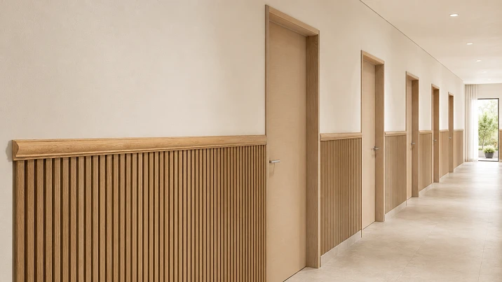
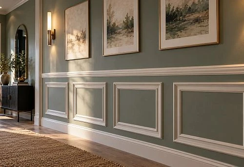
If slat panels in the hallway end at a height of 1.1 m, the MLD-043 border should be ordered not by the total length of the hallway and not by the number of doors. First, measure each physical horizontal section between trims, corners, and ends, then decide where joints are acceptable, and only then lay out the segments across planks 2600 or 2400 mm long. Five door openings do not reduce the task to the formula "perimeter minus door widths": each opening has two junctions, trims may protrude from the wall plane by different amounts, and a short leftover from one plank does not always fit the next wall section.
The main design decision is made before installing the top row of panels. The top of the slat cladding, the axis or bottom edge of MLD-043, door trims, and baseboard should be shown on one elevation. If you first finish the slats exactly at the 1100 mm mark and then apply a 76 mm wide profile, part of the border may end up without support or cover a decoratively important area of the panels. The 1.1 m height should denote an agreed line of the assembly: for example, the top of the slats, the top of the border, or its axis mark. Without such clarification, two installers will read one dimension differently.
For a long corridor, what matters is not so much the physical continuity of the wood through open doorways, but the visual continuity of the horizontal line. MLD-043 ends at each trim and resumes after it at the same height. The line is perceived as unified when the mark, profile orientation, abutment depth, color, and finish character match. If even one segment is raised by 4-5 mm or turned the other way, sliding corridor light makes the error more noticeable than in a separate room.
After reading, you will be able to compile a list of five sections, choose MDF, beech, or oak, calculate the slats without false economy, determine joint locations, and give installers a clear task. If actual dimensions, trim construction, or the base plane are not yet known, it is too early to place a final order: first, a control measurement is needed.
Long corridor with slat panels: why a continuous horizontal line is needed
Panels 1.1 m high work as the lower belt of the wall. In a short hallway, its top can be perceived as local finishing, but in a long corridor, the eye moves along the wall and reads the horizontal line as a whole. Doorways break the material but should not break the composition. The border sets a constant mark above the slats, connects piers of different widths, and explains where the textured lower zone ends and the smooth upper one begins.
This function does not mean that the profile will fix any inaccuracy in the cladding. MLD-043 has its own geometry and is not intended to mask an arbitrary wave of 10-15 mm. If the tops of the slats vary in height, a wide border will either repeat the curvature or leave an uneven gap. Before ordering, check the horizontal base with a laser, and before installing the profile, level the base or adjust the top of the panels according to the agreed node.
Five doors create at least ten abutment points: the left and right sides of each opening. Add to these the beginning and end of the line, internal or external corners, a door portal at the end, a wardrobe, a mirror, an electrical panel, or a technical door. Therefore, the actual number of endings is almost always greater than the number of doors. For each point, one of the following solutions is chosen in advance:
-
straight end butt-jointed to the trim;
-
cutting the profile to fit the trim protrusion;
-
short return to the wall plane;
-
continuation onto the slope, if provided for by the project;
-
end at the corner with mitered cut of two pieces;
-
open decoratively finished end;
-
transition to another profile through a matched connecting element.
In a narrow corridor, a profile with a depth of 17 mm cannot be assessed only from the front. A door casing may protrude by 10–14 mm, a slat system by 15–30 mm including the base, and the upper smooth wall may be in yet another plane. If MLD‑043 is mounted over the slats, its front point shifts further into the walkway. If it is installed on a separate mounting strip above the slats, the thicknesses need to be reconciled so that the border does not look like an accidental shelf.
Before purchasing, it is useful to make a full-size mock-up 500–700 mm long from cardboard, MDF offcut, or inexpensive slat. On it, mark the width of 76 mm and the projection of 17 mm, apply it to the wall at the design mark, and view it along the path of movement. The mock-up answers questions that a small picture cannot resolve: whether the wide line presses in the corridor, whether it conflicts with door handles, switches, signs, and frames, and whether there is enough space between the border and the top of the casing.
If the profile covers too much of the slat area, collides with hardware, or makes a low corridor visually fragmented, MLD‑043 should not be purchased just because it has already been selected in the sketch. It is wiser to reconsider the mark, use a more compact molding, or finish the panels with a flat strip of a different cross-section. A commercial decision begins with compatibility checking, not with mandatory purchase confirmation.
At the start of the project, one can simultaneously buy slat panels for walls for interior finishing and select the top profile, but the specifications must be linked. For panels, the full system projection, width and pitch of slats, background type, mounting method, and actual top mark are fixed. For MLD‑043 — material, orientation, strip length, rear surface position, and the nature of each end.




Wooden border MLD‑043 76 × 17 mm: what the product card confirms
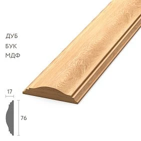
MLD‑043 is presented in the catalog as a wooden border, molding, and casing. It is a linear profile of constant cross-section: it can be used in various assemblies, but this specific article considers a horizontal wall border above slat cladding. This limitation is important. The calculation conditions for a horizontal line across five door openings differ from the calculation of door framing, where one would have to account for two verticals, a top crossbar, and corner joints of each portal.
Verified parameters are collected in the table without prices and current stock levels: they change and must be clarified before payment.
| Execution of MLD‑043 | Profile cross-section | Length of one strip | Typical finishing logic |
|---|---|---|---|
| MDF, sanded "Prestige" | 76 × 17 mm | 2600 мм | Opaque enamel; color of wall, door, or baseboard |
| Beech | 76 × 17 mm | 2400 мм | Solid wood under enamel or agreed translucent finish |
| Oak | 76 × 17 mm | 2400 мм | Solid wood when the wood grain should remain part of the interior |
The card indicates that the available stock item is shipped within three business days, and the average production time for a non-stock item made to order is 5–10 business days. Delivery is available across Russia, with a minimum order of one strip. These conditions are useful for planning, but they do not replace confirmation of the specific configuration: availability of MDF does not mean availability of oak, and today's stock level does not guarantee the same level after project approval.
The cross-section 76 × 17 mm is read as the external profile dimension, but it does not replace the drawing. The width of 76 mm shows the size that the border occupies on the wall facade; the depth of 17 mm is the maximum projection relative to the mounting plane. The back side may have a relief and may not contact the base over its entire area. Before preparing the embedded part or strip, you need to download the product drawing or obtain a sample.
In the card for MDF, "Prestige" and "for enamel" are indicated. "Prestige" refers to the quality of sanding. The enamel-ready version is oriented toward an opaque coating. For solid wood under translucent tinting, it is necessary to confirm the corresponding blank category and make a test coat: the same wood species name does not guarantee a match with the slats in shade, texture, and gloss.
The current price, availability, possibility of a single batch, and preparation time are checked directly in the MLD‑043 card. Do not transfer figures from an old estimate or a saved card image: with a long corridor, even a difference of one slat noticeably affects the final budget, especially for oak.
Our factory also produces:
Wooden molding, wall border, or architrave: how to correctly name MLD‑043
All three names are acceptable because they are specified by the manufacturer, but they denote different roles of the same profile. "Molding" is the broadest name for decorative trim. "Border" accurately describes a horizontal dividing line. "Architrave" indicates possible use around an opening. In the specification, it is better to write: "MLD‑043, horizontal wall border above slat panels." This way, the manager sees the article number, and the installer sees the function.
The term "wooden" in a commercial request covers the category, but in the bill of materials, materials are separated. MDF cannot be called solid wood. Correct lines look like this:
-
MLD‑043, MDF, 76 × 17 × 2600 mm, for enamel;
-
MLD‑043, beech, 76 × 17 × 2400 mm, finish category subject to confirmation;
-
MLD‑043, oak, 76 × 17 × 2400 mm, finish category subject to confirmation.
The words "slat" or "plank" in this article refer to the form of supply and segments of the original trim, but they do not replace the product name. Otherwise, confusion arises with slat panels. In the cutting plan, it is convenient to write "original plank MLD‑043 No. 1," and designate the finished part as "border segment A1."
Orientation is recorded separately. A shaped profile has a top and bottom. If one section is rotated 180°, its shadows and protrusions will not align with the rest of the line. On the drawing, an arrow "top" is placed, and on the back side of the segments, marking is done with a pencil or painter's tape. This is especially useful when parts are painted before installation and laid out in another room.
The correct name also affects the calculation. If MLD‑043 is perceived as a regular door casing, the craftsman may automatically run it vertically around five openings. This is a different volume: vertical posts and lintels will be added to the horizontal sections. If the task is only to connect the line above the panels, vertical framing is not included without a separate decision.
Get Consultation
Why a 76 mm wide profile is suitable for finishing slat cladding
The 76 mm width makes MLD‑043 a standalone horizontal element, not a thin masking strip. On a wall with a vertical rhythm of slats, this size creates a noticeable pause and holds the long perspective of the corridor. But the profile works convincingly only with coordinated proportions.
First, determine what the 1100 mm mark means. Three schemes are possible:
| What is at a height of 1100 mm | Position of the 76 mm wide profile | Practical implication |
| Top of slat panels | MLD‑043 is installed above them or partially overlaps the edge | The common top point of the border will be above 1100 mm |
| Top of MLD-043 | The profile occupies an area approximately from 1024 to 1100 mm | The slats end below or extend under it according to the section |
| Axis of MLD-043 | The profile is positioned approximately 38 mm up and down from the axis | Top and bottom are determined after checking the actual profile |
The dimensions in the table describe geometric logic, not installation tolerance: shaped edges and the rear form are clarified according to the drawing. In practice, it is more convenient to set one measurable edge, usually the top or bottom, rather than a conditional axis. Then the laser line is transferred to all walls without recalculation.
The second parameter is the height of door handles, switches, and other hardware. There is no standard universal mark here: doors and electrical systems are designed for a specific object. If the border crosses a socket or switch, you cannot simply cut a rectangular hole in the shaped profile without assessing the appearance. Usually, electrical hardware is moved, a different mark is chosen, or a symmetrical gap is designed in advance.
The third parameter is the width of the door casing. The horizontal MLD-043 can be wider, narrower, or comparable to it. Matching width is not necessary, but the hierarchy should be clear: the portal remains an independent frame, the border approaches its side part and ends cleanly. If both profiles are shaped and equally active, the meeting point may look overloaded. A full-size sample shows this better than visualization.
The fourth parameter is depth. Suppose the casing protrudes from the painted wall by 12 mm, and the MLD-043 has a maximum extension of 17 mm. With a direct joint, the border will be 5 mm ahead. Leaving such a step with an open end is undesirable: the back part will be visible and a sharp protrusion will appear in the passage. Possible options include return, decorative end cutting, adjustment of the mounting plane, or choosing a deeper casing. These figures are an example of the method; actual extensions are measured on site.
The fifth parameter is the total thickness of the slat system. If the slats protrude by 24 mm, and the MLD-043 is mounted on a smooth wall with an extension of 17 mm, its front point will be 7 mm deeper than the slats. This can be a meaningful step, but not an automatic result. To make the surfaces flush, the back plane of the border would have to be extended by approximately 7 mm; the exact value depends on the relief of its face and the method of joining.
MLD-043 is not suitable without adjustment if a strip narrower than 76 mm remains above the panels, if casings cross its ornament without a neat junction, if the wall has significant curvature, or if the profile narrows a regulatory significant passage. In the latter case, the solution is checked by the designer based on actual dimensions and requirements for the specific object; a decorative article does not replace structural calculation.
Border made of MDF, beech, or oak: which finish to order
The material is chosen before cutting. MDF has a length of 2600 mm, solid beech and oak — 2400 mm, so changing the finish changes not only the surface treatment, but also the number of planks, joint coordinates, and the amount of waste. You cannot first calculate the corridor for 2600 mm, then choose oak and keep the previous list.
MDF molding under enamel
MDF is rational when the horizontal line must be painted with an opaque coating in the color of the upper wall, doors, casings, or baseboard. A uniform surface is convenient for enamel, and the length of 2600 mm allows covering more short wall sections without a joint. In a corridor with five doors, this is significant: many sections are shorter than a full plank, and waste can be redistributed.
MDF is not intended for displaying natural texture under a transparent coating. It cannot be chosen just because the plank is 200 mm longer. The room conditions need to be checked: the entrance area may receive wet shoes, wet cleaning, and microclimate fluctuations. Protection of fresh ends and joints is part of the finishing system; the suitability of a specific material for the object's conditions is confirmed separately.
If an opaque white color is chosen, not only the code but also the gloss is compared. A matte wall, semi-matte casing, and glossy MLD-043 will differ even with the same shade number. A practical sample includes primer, intermediate sanding, and all finish layers on the same material.
For such a solution, one can consider MDF molding under enamel, but the final quantity is determined not by the catalog, but by the map of five sections.
Wooden border made of beech
Beech is a solid wood with a calmer texture compared to oak. It is suitable if the project requires wooden trim, but the finish remains opaque or is done according to an approved sample. For a painted hallway, beech can tie together wooden door elements and panels without forcing a pronounced oak grain to be displayed.
A length of 2400 mm changes the cutting layout. A wall section of 2350 mm fits into one plank with a small nominal remainder, while a section of 2450 mm already requires a joint or a different scheme. The difference of 50 mm turns a solid piece into two, so a control measurement after installing the casings is mandatory.
When tinting, beech and oak give different results under the same composition. Selecting a shade from a paint fan is not enough. A test coat on a piece of MLD‑043 or on a blank of the same species and category is needed, next to the slat panel and casing under the hallway lighting.
Oak molding with preserved texture
Oak is chosen when the horizontal line should continue the natural wood theme: for example, panels are veneered with oak, doors have an oak finish, and the baseboard is made in a similar species. The expressive texture turns every joint into a visually sensitive area. Matching the profile cross-section does not guarantee a calm connection: the direction of the fibers, the tone of the lamellas, and the nature of the cut may differ.
For a semi-transparent finish, the category "for tinting" is confirmed in advance, if it is available for the required configuration. A blank "for enamel" may have contrasting lamellas that an opaque coating will hide, while a transparent one will emphasize. It is desirable to receive all planks in one batch, sort them before cutting, and turn them so that adjacent sections do not create a sharp color jump.
Oak should not be purchased just as a formally "most expensive" option. If the entire profile will be covered with dense enamel, and adjacent elements do not require solid oak, the visual advantage of the texture disappears. Then the decision is made based on construction, budget, requirement for solid wood, and cutting layout, not on a price hierarchy.
Comparison for a corridor with five doors
| Criterion | MDF | Beech | Oak |
| Plank length | 2600 мм | 2400 мм | 2400 мм |
| Main finish | Opaque enamel | Enamel or agreed tinting | Translucent finish or enamel per project |
| Texture as part of the design | No | calm | Pronounced |
| Sensitivity of joints to pattern matching | Low after quality enamel | Medium | High with transparent coating |
| Risk when reordering | Possible difference in finish batch | Possible difference in wood and tone | Especially noticeable difference in texture and tone |
| What determines the choice | Color, conditions, map 2600 mm | Requirement for solid wood, finish, map 2400 mm | Visible wood, batch, stain sample, map 2400 mm |
After selecting the material, checking the finish, and preliminary calculation, you can buy the wooden border MLD-043. The request includes not only the number of planks, but also the material, blank category, requirement for a single batch, desired deadline, and a question about current availability.
How to measure five wall sections between doorways
Measurements are taken after the finished boundaries are known. The rough door frame and the installed casing give different lengths of the wall section. If you order molding based on the masonry and then add casings 80–100 mm wide, each segment will be longer than needed. With five openings, the error will repeat multiple times and create useless offcuts.
First, the corridor is depicted as a flat layout, not as a top-down plan. The horizontal line must be visible in full. Each wall is assigned a designation, for example K-1 and K-2, and each section — A1, A2, A3, A4, A5. Doors are marked D1–D5. If there are additional openings on the opposite wall, they cannot be mixed into one sequence: cutting can be combined later, but geometry is tracked for individual walls.
For each section, record:
-
the clear length between actual junction points;
-
the type of left end;
-
the type of right end;
-
the mark of the top or bottom edge;
-
condition of the base;
-
the allowance for a direct joint within the section;
-
the visibility of the section from the entrance;
-
the presence of switches, hatches, and other obstacles;
-
full removal of battens, curb, and trim;
-
requirement for the direction of the wood grain pattern.
Net length is measured along the installation line of the back side of the profile. One section cannot be measured from the face point, another from the wall, and a third between the decorative tops of the trims. For a shaped profile, the length of the face edge near the corner may differ from the length of the back line. For a straight joint to the trim, this difference is usually controlled by a template and the method of end processing.
The measurement is repeated at least at two close marks: at the supposed top and bottom of MLD-043. If the distance between the trims differs, the pier or portals are not parallel. The profile cannot be cut "by average" without a decision. The craftsman selects a reference edge, takes a template, and determines where a minimal compensation gap or adjustment is acceptable.
The height is transferred with a laser from one permanent base. Measuring 1100 mm from the finished floor near each door is risky if the covering has unevenness, thresholds, or different levels. It is necessary to decide what is more important: the absolute horizontal level by laser or a constant distance from the local floor. In a long corridor, the horizontal level is usually read, but on a stair landing or with a pronounced slope, the decision may be different.
Working measurement sheet
| Section | Net length, mm | Left | Right | Joint acceptable | Comment |
| A1 | As per actual | Start of wall / trim | Door trim D1 | Yes / no | View from entrance |
| A2 | As per actual | Door trim D1 | Door trim D2 | Yes / no | Switch, light |
| A3 | As per actual | Door trim D2 | Door trim D3 | Yes / no | Most noticeable pier |
| A4 | As per actual | Door trim D3 | Door trim D4 | Yes / no | Possible short remainder |
| A5 | As per actual | Door trim D4 | Casing D5 / end | Yes / no | Corner or open end |
If there are physically six, seven, or more sections, the table is expanded. The number "five" in the topic is a design situation, not a rule forcing different wall pieces to be combined. An error in numbering is dangerous: a strip cut for A3 may have the correct length but incorrect endings for A4.
Checking the depth at each door portal
Using a short ruler or template, measure how much the casing protrudes relative to the mounting plane of the border. Values are recorded separately on the left and right: one portal may be installed with a slight step due to wall curvature. Then a profile fragment or its cross-section template is applied, and the joint is selected.
If the casing is deeper than MLD‑043, the border can be carefully brought to its side plane with a straight end. If MLD‑043 is deeper, a machined ending, return, or base modification will be required. If the profiles are flush, even a small cutting error will be visible, so a clean perpendicular cut and gap control are needed.
Control measurement after the base and casings
The first measurement is needed for the budget and preliminary quantity. The final one is for cutting. Between them, plaster, paint thickness, door portal position, panel tops, and mounting strip may change. Strips can be ordered in advance with a reasonable reserve, but cutting into finished parts before re-measurement should not be done.
For remote ordering, millimeters are provided to the manager, not rounded meters. A note like "wall section about 1.7 m" is suitable for preliminary estimation, but not for a cutting map. The correct note is "A1: 1694 mm along the rear mounting line, both ends straight, right side adjoining casing D1".
How to calculate the number of wooden molding strips
The calculation consists of two different tasks. The first is to determine the sum of net lengths. The second is to place all finished segments into the original strips. It is the second task that answers the question of how many items to buy.
Let's denote the lengths of the five sections as L1…L5. Net footage:
Lnet = L1 + L2 + L3 + L4 + L5.
Arithmetic minimum for MDF:
Nmin = round up (Lnet ÷ 2600).
For beech or oak:
Nmin = round up (Lnet ÷ 2400).
This is only the lower bound. It does not account for whether each solid segment fits into a strip, how many straight joints are allowed, how much length is lost in trimming, whether the remainder can be used with the required orientation, and whether a reserve from the same batch is needed.
MDF length 2600 mm
Any section up to 2600 mm can theoretically be made solid from one strip. A section of 2601 mm already requires a joint, even if the excess is only 1 mm. Therefore, dimensions close to the full length are checked after installing the casings. The nominal allowance of 20–30 mm may disappear when removing a damaged end and performing final trimming.
Short piers are advantageous to combine. For example, parts 1250 and 1200 mm give 2450 mm from one plank, leaving 150 mm before accounting for cuts. But two pieces of 1400 and 1300 mm already give 2700 mm and do not fit. The total length of the pair differs by only 250 mm, but the consumption is a whole plank.
Array length 2400 mm
For beech and oak, the threshold for a solid part is lower. A pier of 2350 mm mathematically fits, but the 50 mm allowance is too small for end trimming and fitting. A section of 2450 mm must be divided. With transparent finishing, the joint coordinate is chosen not only by length but also by the wood grain pattern.
Array remnants are more valuable as repair material from the same batch. However, storing a long piece makes sense only with marking and under proper conditions. A warped or unidentifiable offcut is not a full-fledged reserve.
Cutting map
First, desired joints are placed on the layout. Then each future part is recorded as a separate line and distributed across planks. You cannot start by filling a plank with random pieces: this way the joint appears where it is more convenient for arithmetic, not for composition.
| Source plank | Total length | Part 1 | Part 2 | Cut losses | Remainder | Remnant assignment |
| № 1 | 2400/2600 | By map | By map | By actual tool | Calculation | Sample / repair / other area |
| № 2 | 2400/2600 | By map | If present | By actual tool | Calculation | Is specified |
| № 3 | 2400/2600 | By map | If present | By actual tool | Calculation | Is specified |
The kerf depends on the tool and the blade, so it should not be invented in the article. The contractor specifies the actual value in the map. If three parts are obtained from one plank, losses occur between them and during final preparation of the original ends. Zero remainder on paper almost always means a shortage on site.
Use of short remnants
A remnant is useful if it matches an actual part. A 420 mm fragment can be used on a 400 mm wall section if the allowance is sufficient and both ends fit. But the same fragment cannot replace a 650 mm part, no matter how much total footage remains in other offcuts.
With enamel, short parts can be used more freely because the color and joint can be finished with an opaque system. With transparent tinting, every additional seam is more visible. A short 80–150 mm "extension" near a trim often looks like a cutting error. It is better to shift the joint, redistribute parts, or order another plank.
Technological allowance
Universal 10% does not replace a map. For five short sections, 10% may provide enough total length, but not the required combination. For one long section, it may turn into a useless short remnant. The reserve is accepted in one of the following ways:
-
a separate full plank for a complex oak project;
-
a confirmed long remnant capable of replacing a specific part;
-
an allowance on each segment up to the control trimming;
-
a reserve for an external corner or open end;
-
a general project reserve if MLD‑043 is used on several walls.
The solution depends on the cost of stopping work. In a private corridor, reordering a single plank may be acceptable. In a hotel, office, or facility with a fixed opening date, crew downtime and repeat delivery are often more expensive than a pre-planned reserve.
Example calculation of MLD-043 for five corridor sections
Let's consider a training example. These are not dimensions of a real object, but a demonstration of the method. After installing five door portals, the following sections were obtained:
| Section | Net length | Feature |
| A1 | 1700 мм | We see from the entrance, a solid element is needed |
| A2 | 1250 мм | Short wall section between D1 and D2 |
| A3 | 2350 мм | Long visible section |
| A4 | 1450 мм | Can be combined with part of the long section |
| A5 | 3050 мм | Always has a joint regardless of material |
Sum:
1700 + 1250 + 2350 + 1450 + 3050 = 9800 mm.
Arithmetic for MDF
Four planks of 2600 mm each give:
4 × 2600 = 10,400 mm.
Nominal excess:
10,400 − 9,800 = 600 mm.
At first glance, four planks are enough. But if A1, A2, A3, and A4 must remain whole, they already occupy four original planks or require favorable packing. A5, 3050 mm long, needs to be divided into at least two parts. Attempting to place it with one additional joint in the remaining capacities does not work.
Free spaces after the whole pieces are:
-
after A1: 900 mm;
-
after A2: 1350 mm;
-
after A3: 250 mm;
-
after A4: 1150 mm.
To make A5 from only two parts, you need two fragments with a total length of 3050 mm. No pair of free spaces gives 3050 mm: 1350 + 1150 = 2500 mm, 1350 + 900 = 2250 mm. Therefore, four planks cover the total length only at the cost of splitting A5 into at least several short pieces. For a visible horizontal line, this is poor economy.
Practical variant with one joint on A5 uses five planks:
| MDF plank | Layout | Nominal remainder before accounting for cuts |
| № 1 | A1 — 1700 mm | 900 мм |
| № 2 | A2 — 1250 mm + part of A5 — 1350 mm | 0 мм |
| № 3 | A3 — 2350 mm | 250 мм |
| № 4 | A4 — 1450 mm | 1150 мм |
| № 5 | part of A5 — 1700 mm | 900 мм |
A5 is assembled from 1350 + 1700 mm. The joint coordinate is chosen based on light, visibility, and base, not automatically at a distance of 1350 mm from the left edge. If the joint needs to be shifted, the sizes of the two parts change, but it is checked whether the first part fits next to A2.
In line No. 2, zero remainder means that the finished sizes of 1250 and 1350 mm occupy the entire plank. The actual cut and end preparation will require length. Therefore, such a map cannot be sent to production as final without allowance. Three solutions are possible: change the A5 split, use part of another remainder, or keep the sixth plank as a safe reserve. This edge case shows why even a practical table must account for the tool.
For example, A5 can be split into 1320 + 1730 mm. Then plank No. 2 contains 1250 + 1320 = 2570 mm and leaves 30 mm before accounting for cuts. The second fragment of 1730 mm fits into plank No. 5. The margin is still small, so the executor sets an allowance according to their process. If 30 mm is not enough, a different combination is required.
Arithmetic for beech or oak
Five planks of 2400 mm give:
5 × 2400 = 12,000 mm.
Nominal excess:
12,000 − 9800 = 2200 mm.
The quantity by total length is five. The layout can be built with one joint on A5:
| Solid wood plank | Layout | Nominal remainder before accounting for cuts |
| № 1 | A1 — 1700 mm | 700 мм |
| № 2 | A2 — 1250 mm + part of A5 — 1100 mm | 50 мм |
| № 3 | A3 — 2350 mm | 50 мм |
| № 4 | A4 — 1450 mm | 950 мм |
| № 5 | part of A5 — 1950 mm | 450 мм |
A5 is made from 1100 + 1950 mm. But planks No. 2 and No. 3 have only 50 mm of nominal remainder each. After final trimming and cuts, the margin may be insufficient. A safe layout must be confirmed by the carpenter. A sixth plank, redistribution across other walls, or using a pre-existing long offcut from the same batch is possible.
What the comparison shows
MDF is longer, but in the selected set of sections, its arithmetic minimum of four planks creates an excessively fractional A5. Five planks give an acceptable composition, but one combination is still close to zero margin. Solid wood immediately requires at least five planks by total length and also needs control of allowances.
It cannot be concluded that both materials are 'the same in consumption' in general. The equality arose only for specific five sizes and the requirement of no more than one joint per A5. If A3 is reduced to 2250 mm or A2 is increased to 1320 mm, the packaging will change. Each real corridor is recalculated anew.
How to account for the second wall of the corridor
If MLD‑043 goes on both sides, the maps are combined after independent measurement. The 900 mm remainder from wall K‑1 can cover a 870 mm section on K‑2, reducing the total order. But specific parts need to be combined, not percentages. For solid wood, sorting by tone is additionally considered: a remainder of the correct length that differs sharply in color is better left for a less visible place or sample.
Where to place MLD‑043 joints in a long corridor
The best joint is one that has continuous support, does not fall into the most visible light zone, and does not create a short piece near the door trim. In a corridor, the gaze often goes almost parallel to the wall. This angle emphasizes even a small step between the ends, so the quality of the base and the alignment of the profile are more important than in a frontally viewed room.
The joint should not be placed directly above a gap between slats if the border rests on an intermittent system. Under it, a solid mounting zone is needed that can hold both edges. The coordinates of the connections are transferred to the base before closing the wall.
Compositionally, several options are acceptable:
-
along the axis of a symmetrical pier, if a door, lamp, or panel supports the central line;
-
closer to the less visible corner, but without a short fragment;
-
in the zone covered by the open door during a normal movement scenario;
-
in an area with even diffused light instead of a sliding beam;
-
above the reinforced mounting strip, if the spot visually appears neutral.
Do not automatically hide the seam right next to the trim. An extension piece 100–200 mm long looks like a correction of an error and has weak support. It is better to make two more proportionate fragments or move the joint to an adjacent section using a common layout map.
With enamel, a straight joint can be prepared, filled with a compatible material, and painted.
Return to the wall
If the border protrudes more than the trim, its end can be returned to the wall plane with a short piece using a miter joint. The return covers the cut and turns the profile into a finished shape. However, it consumes additional length, requires precise cutting, and creates a small element that cannot be considered negligible.
The size of the return is determined by the actual depth and shape, not just the number 17 mm. The layout map includes both pieces of each return and allowance for test cuts. With ten endings, even small elements collectively affect the number of planks.
Trimming to match the trim profile
A shaped end can be fitted to the relief of the trim, but this is a labor-intensive joinery connection. It is justified in complex finishing if a straight end and a return disrupt the composition. First, make a template of one joint, then repeat it on the other doors. The trims must be installed identically; otherwise, each joint is fitted individually.
Transition through insert
Sometimes a small smooth transition piece is inserted between MLD-043 and the trim. It resolves the conflict between two active profiles and allows depth alignment. This is a separate specification item: material, size, color, and number of inserts must be calculated. Improvising with offcuts on site without an approved sample is not allowed.
Continuation around the portal
If MLD-043 is also used as a trim, the horizontal can transition into the door framing. Then the task is no longer about calculating five breaks: vertical posts, top lintels, corners, and profile orientation are added. This option is calculated as a separate scheme. It should not accidentally arise after purchasing planks only for a horizontal border.
How to choose a unified node
For each portal, fill in a table:
| Opening | Trim protrusion | MLD-043 protrusion | Base solution | Exception |
| D1 | As per actual | 17 mm from its mounting plane | Direct / return / trimming | Specify |
| D2 | As per actual | Same | Same | Specify |
| D3 | As per actual | Same | Same | Specify |
| D4 | As per actual | Same | Same | Specify |
| D5 | As per actual | Same | Same | Specify |
If the values differ, first check the installation of the platbands and the flatness of the walls. Making five different decorative solutions to compensate for construction inaccuracy is a last resort, not normal practice.
How to align the height of the border with slat panels
The phrase "panels up to 1.1 m" is insufficient for a work specification. A specific edge must be indicated. On the elevation, an absolute mark is set relative to the accepted finished floor level, and a side section is drawn.
The section includes:
-
base wall;
-
adhesive, battens, or panel backing;
-
face slat;
-
top end of the panel;
-
mounting plane MLD-043;
-
profile 76 × 17 mm in the correct orientation;
-
smooth finish above;
-
door casing in the junction area.
There are three common schemes. In the first, the slats fit under the bottom edge of the border, and the profile is attached to a separate strip above. This gives a clear separation but requires precise alignment of the tops of the slats. In the second, MLD-043 partially overlaps the top of the panels and masks a small technical edge. Then the rear plane must account for the full projection of the slat system. In the third, the border is placed in front of the panels, and the slats are adjusted to it later. This order is only convenient with accessible mounting and a pre-prepared base.
Do not glue a wide profile only to the tops of individual slats without checking the structure. The support will be intermittent, the joint may fall between protrusions, and adjacent slats may have different depths. A continuous strip or another calculated zone connected to a solid base is needed.
In a long corridor, the mark is checked at several points and at all doors. The laser shows the horizontal level but does not guarantee the straightness of the wall in plan. The rule reveals waves in depth. If the mounting strip bends, MLD-043 will follow it or detach from the base in dips.
Special attention is paid to corners. If the line transitions to the end wall, two mounting planes must meet without a step. An internal or external miter cut will not fix the depth difference. First, align the base, then cut the profile.
Wooden baseboard under slat panels: how to assemble the lower part of the wall
The border forms the top of the lower belt, the plinth forms its base. Between them are panels about 1.1 m high. These elements do not have to have the same cross-section or material, but must be part of one system.
If MLD‑043 is painted in the color of the doors, the plinth can be continued in the same color. Then the vertical casings connect the upper border and the bottom of the wall. If MLD‑043 is tinted to match the oak slats, and the plinth is white, the horizontals get different weight: the top emphasizes the wood, the bottom supports the doors and the smooth wall. Both solutions are possible after checking the layout.
The plinth should not accidentally protrude beyond MLD‑043 so much that the lower part of the wall seems heavier than the upper part. Compare the maximum projection of both profiles, the thickness of the panels, and the position of the casing. At the door, three parts meet in a small area; if each has its own depth, a cascade of steps appears.
Before buy wooden skirting board, form a combined cross-section node. Check the height, projection, method of termination at the casing, material, and finish. The plinth is calculated separately: door openings also break the lower line, but corners, furniture, and built-in wardrobes may differ from the upper border.
The lower edge of the slatted panels must be protected and neatly finished. You cannot assume that any plinth will automatically cover the gap. If the slats protrude more, the plinth may go under them; if the plinth is deeper, a dust shelf forms above it. The solution is shown in a section before ordering both types of trim.
When to paint MDF molding — before or after installation
There is no universal order. The choice depends on the quality of the base, requirements for joints, method of fastening, and conditions on site. For a corridor with many doors, a combined scheme is often used: the main preparation and part of the layers are done before installation, joints and fastening points are finished on the wall, then a common finish is applied.
Painting before installation
Advantages — convenient access to the profile, no risk of staining panels and doors, the ability to work in a prepared painting area. Each strip can be inspected in good light. Ends and back areas are treated according to the technical map, especially if they may come into contact with moisture.
Disadvantage — after cutting, fresh ends appear, and fastening may damage the coating. Joints remain visible if the finish does not unify the parts. Fully finished long elements require careful transport and storage.
Painting after installation
Advantage — a single color line and the ability to finish joints on the wall. Disadvantage — you need to carefully protect slatted panels, casings, floor, and upper wall. In a narrow corridor, the painter works next to finished surfaces, and through traffic increases the risk of dust and touches.
Combined system
The profile is primed and prepared before installation, installed, joints and fasteners are finished, then a final coat is applied. Specific compatibility of primer, adhesive, filler, and enamel is confirmed by material manufacturers and the contractor. Random compounds cannot be used just because each one is individually intended "for wood."
For oak under a transparent finish, most of the finishing can be conveniently coordinated on samples in advance. Filling the joint with opaque putty may disrupt the grain pattern. The craftsman chooses the joint and touch-up, considering that completely hiding the boundary between two wooden pieces is not always possible.
Official STAVROS recommendations include dust removal, priming, sanding after the primer dries, and applying the topcoat. The specific number of coats and drying times are taken from the instructions of the chosen system, not mechanically transferred from a general article.
How to install a wooden border on a prepared wall
Installation begins not with adhesive, but with acceptance of the substrate and dry layout. All pieces are laid out by section, checking markings, orientation, color, and allowance. A template for the end is placed near each doorway.
Preparation of the Base
The substrate must be strong, dry, level, and compatible with the chosen adhesive and mechanical fastening. Weak paint, dusty putty, or soft acoustic backing does not become a reliable support just after applying the mounting compound. The load is transferred to a solid wall or a calculated embedded anchor.
The mounting strip is checked with a straightedge along the corridor. Local protrusions are removed or corrected before installation. Attempting to level the profile with a thick layer of adhesive creates floating depth and a step at the joint.
Marking
A laser sets the selected edge of MLD-043. The boundaries of the pieces and coordinates of connections are transferred to the wall. The layout is checked at doors: the line should arrive at the same part of the trim, unless the project specifies exceptions.
Hidden utilities are marked on the wall. Fasteners must not hit cables or pipes. The presence of a switch near the line requires a known route in advance, not drilling "at a safe distance" based on assumption.
Cutting and dry fitting
Each piece is cut with an allowance according to the master's technique, then fitted to actual dimensions. First, the most critical ends and corners are done, after which the straight joint is refined. If you start with the final size of the central piece, there will be nothing to correct an inaccurate portal with.
Dry fitting means that the entire section is assembled without final fixation. Check the level, tightness of joints, oak grain pattern, alignment of relief, and absence of an unexpected short filler piece.
Mounting
The method depends on the material, weight of the piece, substrate, and finish. Adhesive is chosen based on surface condition; mechanical fixation can hold the profile during curing and increase reliability if the joint allows it. The specific step and type of fastener are determined by the installer. A universal number without knowing the wall would be a fabrication.
Official manufacturer recommendations distinguish between compounds for unpainted and painted or primed substrates. Before work, check the current recommendation and compatibility with the actual material. Adhesive does not replace a solid substrate and does not compensate for a wavy wall.
Acceptance
The line is checked not only up close, but also from the beginning and end of the corridor under working lighting. Check:
-
matching height on all sections;
-
identical profile orientation;
-
absence of steps in straight joints;
-
a unified joint at five doors;
-
cleanliness of ends and returns;
-
absence of damage to the slats and trims;
-
uniformity of color and gloss;
-
preservation of the marked repair remainder.
A small gap, unnoticeable from the front, can become a dark line in perspective. Acceptance is carried out before dismantling the protection and the crew leaves, when the joints can still be adjusted according to the accepted technology.
Mistakes when buying MLD‑043
Subtract the width of five doors from the length of the corridor
The error occurs when the room plan is taken as a cutting map. The resulting sum does not show the number of individual parts, the types of endings, or the ability to place them in the planks. The consequence is a formally sufficient footage and a shortage of the needed long piece. Prevention — the A1–A5 list and packing parts according to the original planks.
Counting different edges as the 1.1 m mark
The designer means the top of the panels, the installer means the top of the border, the painter means the color boundary. As a result, the line shifts by tens of millimeters. Prevention — a side cut and one signed control edge.
Calling MDF solid wood
Such simplification hides the difference in material, length, and finish. After switching to oak, the 2600 mm map becomes invalid. Prevention — full naming of each specification line.
Order four MDF strips only by the total of 9800 mm
In the training example, four strips give 10,400 mm, but force excessive splitting of the 3050 mm section. Consequence — several visible seams instead of one. Prevention — limit the allowable number of joints before cutting and check the packaging.
Use a universal 10% without a map
Percentage does not guarantee the required remainder length. You can have 1000 mm of total offcuts and not get a solid 700 mm piece if the remainders are distributed as 300, 350, and 350 mm with unsuitable ends. Prevention — assign a specific role to each useful remainder.
Place a short extension near the trim
It appears when a long segment is cut without a general layout. A 100–150 mm piece highlights the error and holds worse. Prevention — redistribute the joint before cutting or use an additional strip.
Fail to measure the trim protrusion
MLD‑043 with a depth of 17 mm may protrude forward and expose the end. Consequence — a visible step and a hazardous sharp edge in the passage. Prevention — a cross-sectional template of the assembly at each door.
Buy oak "under enamel" for transparent tinting
For the covering category, lamellas may not be matched by color and texture. A transparent finish will reveal differences. Prevention — confirm the category for tinting and perform a test coat before ordering the entire batch.
Cut the planks before installing the trims
Finish boundaries change, parts turn out longer or shorter. Prevention — preliminary calculation for purchasing and control measurement for cutting.
Attach the border only to the tops of the slats
Intermittent support does not hold the joint edges and repeats the depth difference. Prevention — a solid, strong base according to the design cross-section.
Not checking the delivery path
Planks of 2400 and 2600 mm may not fit into the elevator, stair turn, or an already installed door portal without risk of damage. Prevention — check the route, horizontal storage location, and delivery order before payment.
Mix batches on the most visible wall
For enamel, the difference may appear in preparation, for oak — in texture and tone. Prevention — order the required quantity in one batch, sort the parts, and store a marked reserve.
Fix the price and balance in the article or long-term estimate
Commercial data changes. Consequence — a decision is made based on an outdated figure. Prevention — before payment, open the card, confirm the current price, availability, terms, and packaging.
When it's better not to buy MLD‑043
A profile is not needed if the task comes down to hiding a rough transition that should be corrected with a base. The border will follow the wave or emphasize it. First, level the top of the panels and the wall.
You should refuse the purchase or switch to a more compact cross-section if the 76 mm strip overlaps an important part of the slat pattern, collides with switches, ends up too close to the door lintel, or visually divides a low hallway into many narrow horizontals.
MLD‑043 is impractical under a transparent finish if only a version that doesn't match the slat selection is available, and the wood difference is unacceptable. In that case, choose enamel, another material, or a profile with a confirmed category.
You should not buy the product before measuring if the trim hasn't been chosen yet. Their width and projection determine the length of five sections and the type of ten junctions. You can preliminarily set a budget, but the final quantity remains unconfirmed.
Finally, a separate border may be unnecessary if the slat panels already have a factory top finish that matches the doors and looks cohesive. Adding a second active profile will make the wall heavier. A full-size mockup helps make an honest decision before purchase.
What to order along with the wooden molding
The set is formed based on the assembly, not on the principle of "everything from one category." In addition to MLD‑043, you may need slat panels, baseboard, mounting strip, finishing materials, approved adhesive, mechanical fasteners, protective materials, and samples. The exact set is determined by the contractor.
If the project uses several wooden profiles, it's convenient to order wooden linear products one agreed specification. This helps to check the breed, finish category, batch, and combination of cornice, molding, and plinth. The link does not mean that MDF should be replaced with solid wood: materials are selected separately.
Useful before ordering:
-
sample MLD‑043 or profile drawing;
-
fragment of a slat panel with a full base;
-
sample of a door casing;
-
color swatch on the selected material;
-
template for direct abutment and return;
-
map of five sections and joints;
-
list of source slats;
-
marking of corridor and door sides.
The mounting compound is purchased after determining the base. The same adhesive is not automatically chosen for raw wood, primed MDF, painted walls, and laminated surfaces. Compatibility is confirmed by the manufacturer's instructions for the compound and the contractor's recommendations.
For alternative sections, you can Buy wooden molding in the profile section. Such a link is useful if the MLD-043 layout, 76 mm wide, turned out to be too large, or its 17 mm projection does not align with the casing. You should compare not only the front view, but also the length of the strip, material, back shape, and available finish categories.
How to buy MLD-043 and slat panels as one set
A joint order starts with a single list, but the items remain separate line items. For panels, the area or modules are calculated according to the manufacturer's system; for the border, segments and strips are calculated. You cannot convert square meters of cladding into the quantity of MLD-043 without the length of the horizontal line.
In the request to the manager, specify:
Need MLD-043 76 × 17 mm as a horizontal border above the slat panels in the hallway. Material — [MDF/beech/oak], finish — [specify]. There are five sections with a length of [list in mm] and five doorways. Please confirm the length of the strip, current price and availability, the category of the blank, the possibility of a single batch, preparation time, and delivery conditions. Preliminary quantity — [number] strips according to the attached cutting map. Final cutting is performed after a control measurement of the casings.
Installers are given a separate task:
The control edge of MLD-043 runs at the mark [mm] from the accepted finished floor level. The orientation of the profile is shown in the section. A solid base is required along the entire line. Coordinates of straight joints: [list]. At doors D1–D5, the [name] assembly is used; exceptions are specified separately. The slat panels end [under the border/at its lower edge/according to another agreed assembly].
Commercial and installation documents should not be combined into one message. The manager needs the article number, material, quantity, and deadlines. The builder needs geometry, base, marks, and junctions. When this data is mixed, the price or warehouse stock distracts from critical installation information.
Pre-payment checklist
-
exact material MLD-043 selected;
-
length confirmed as 2600 or 2400 mm;
-
five sections measured between finished boundaries;
-
each end has a designated node;
-
permissible connections marked on the layout;
-
all parts placed in original strips with allowances considered;
-
reserve has a specific purpose;
-
category for enamel or tinting confirmed;
-
batch, current price, availability, and lead time verified;
-
delivery, packaging, and introduction path are calculated;
-
the base for the curb is coordinated with the installer;
-
the 1.1 m mark is interpreted as a specific edge;
-
the baseboard, trims, and panels are checked for depth;
-
the finishing sample is approved under actual lighting.
If at least the measurement of finished trims and a cutting map are missing, you can reserve a budget, but do not consider the order finally ready.
Result: how many MLD‑043 slats to order for the corridor
There is no single number without the dimensions of five sections. The correct answer is obtained in four stages: measure the clean segments between trims, assign allowable connections, lay out parts across 2600 or 2400 mm slats, then add a justified reserve. The profile width of 76 mm affects the mark and composition, the depth of 17 mm affects the junction with trims and the plane relative to the battens.
In the training example with sections of 1700, 1250, 2350, 1450, and 3050 mm, the clean length is 9800 mm. Four MDF slats of 2600 mm formally give 10,400 mm, but require excessively splitting the long section. Five slats allow keeping one joint, although allowances still need to be checked. For beech or oak, the arithmetic minimum is five slats of 2400 mm; the map is also close to the limit on individual cuts and requires confirmation by a craftsman.
The material is chosen not by a single length. MDF is rational under enamel, beech — when solid wood with a calm texture or a covering finish is needed, oak — when the natural pattern must remain visible. For a semi-transparent finish, the blank category and batch are confirmed.
A horizontal line through five doorways becomes convincing when all ten junctions are resolved identically, the profile is oriented with one side, the joints rest on a continuous support, and the height is transferred from a common base. After such preparation, the customer orders not abstract linear meters, but a set of parts for a specific hallway.
Frequently asked questions about the wooden border MLD-043
What to do if one of the five openings does not yet have a casing?
For a preliminary estimate, you can use the design width of the selected casing, but the finished piece next to this opening is not cut. In the list, the point is marked as unconfirmed. After installing the portal, take the final size and check the offset: a change in width affects the length of two adjacent sections at once, and a change in depth affects both junction nodes.
What to do if the casings of five doors have different widths?
A single horizontal line is still possible if the control mark and the method of finishing MLD-043 match. Each section is measured between its actual boundaries; you cannot use one standard correction for all doors. On the layout, it is useful to show the width of each casing so that a short wall segment does not disappear after installing a wider portal.
Can the border be interrupted by a built-in wardrobe at the end of the hallway?
Yes, if the end point is designed. The profile can be brought to the side panel of the wardrobe, finished with a return to the wall, or continued along the visible part of the furniture as a separate agreed element. Behind the wardrobe, MLD-043 is usually not used without reason, but possible furniture dismantling should be considered: after it, an unfinished line will remain on the wall.
What to do if an electrical panel or inspection hatch is located at the border mark?
The decorative profile should not block opening and maintenance. Consider a gap with two identical endings, moving the mark, changing the hatch position at the design stage, or designing the cover as a separate element. Add two more end points to the map; the door length cannot simply be subtracted from the total footage without resolving the edges.
How to route MLD-043 through an internal corner after the fifth door?
The line is continued onto the adjacent wall with two pieces fitted to the actual corner. The length is measured along the accepted mounting edge of each plane. The room corner cannot be assumed in advance to be exactly 90°: first check the base with a template, then set the cut. Both segments are included in the overall cutting plan.
What to do with a very short wall section between the trim and the corner?
First, check whether the full MLD-043 profile fits on it and whether two terminations can be safely made. A fragment 60–100 mm long may look random and be poorly secured. Sometimes it is more rational to extend the trim to the corner, abandon the border on that segment, or modify the portal assembly. The decision is made on a full-size mockup.
Can MLD-043 profiles made of MDF and oak be joined on the same line?
Technically, the profiles have the same cross-section, but mixing materials complicates finishing and joint behavior. Under a clear coating, MDF will not continue the oak texture; under enamel, the visual difference is reduced, but the substrates and fresh ends are prepared using their own techniques. If the mixing is caused only by a shortage of one strip, it is safer to recalculate the set for a single material.
How to account for returns to the wall in the quantity of strips?
Each return is a separate piece, not a free offcut. It requires a length based on the actual profile depth, two compatible cuts, and an allowance for fitting. With ten terminations, the sum of returns and test cuts can change the order. First approve one sample of the assembly, then add all pieces to the plan.
Can one long leftover be used for both test painting and installation?
Yes, but first reserve the final length of the future piece with an allowance. The test coating is done on the part that will definitely remain waste. If the entire leftover is coated without marking, it may no longer match the painting sequence of the main set or may end up shorter than the required segment after removing the test area.
How to mark parts for a hallway with identical doors?
One length is not enough. On the back side, indicate the wall, section, left and right end, top of the profile, number of the original plank, and installation sequence. For example: "K-1 / A3 / left to D2 / top ↑ / plank 4". Apply the marking in a way that will not show through the finish and will not damage the front surface.
What to do if one plank noticeably differs in tone after delivery?
Before cutting, compare it with the rest of the batch under working lighting. For clear oak, the differing piece can be distributed to less noticeable areas or a replacement can be agreed upon; for enamel, assess the quality of the base and compatibility of the preparation. Do not cut the disputed plank until a decision is made, since the possibility of return or replacement depends on the seller's terms and the condition of the product.
Can planks be stored standing up before installation?
The storage method must comply with the manufacturer's recommendations and preserve the geometry of long linear elements. Accidental support on one end or leaning against a wall can create stress and deformation. Prepare a dry, protected place on site in advance, where the parts do not obstruct passage and do not get hit by doors or tools.
What will change if the doors open toward the hallway?
Check the trajectory of the door leaf, handle, and stopper relative to the 17 mm protrusion and the chosen mark. The leaf itself usually passes in a different plane, but the handle or limiter may come close to the border. Identify the conflict on the plan and full-size template; the decorative profile should not become an unplanned door stop.
How to finish the area where wallpaper starts above the slats?
MLD-043 can separate materials if the wallpaper edge is prepared along a straight line and the profile has its own solid base. Decide in advance whether the wallpaper goes under the border or up to its edge, and in what order the painting work is done. The profile should not be held only by the weak top layer of wallpaper.
Should the direction of movement be taken into account when sorting oak planks?
Yes. From the most frequent entry point, a long perspective, joints, and tone changes are visible. More uniform pieces are placed on main wall sections, while expressive or contrasting ones are placed where they are supported by a door, corner, or are less noticeable. Sorting is done before cutting, because after assigning short segments, rearrangement is limited.
How to accept a set before starting panel installation?
Check the article number, material, cross-section, length, and number of planks; inspect the face surfaces and ends; sort the products by tone; apply a transverse template to the trim and mounting strip. Then verify that the cutting map matches the actual delivery. If the configuration differs from the specification, panels should not cover the base until the assembly is clarified.