Article Contents:
- What furniture data is needed before choosing supports
- What changes in a turned leg by height
- The final furniture height is measured from the selected body plane
- Why leg height is not equal to floor clearance
- How to estimate diameter without arbitrary coefficients
- Two real SKUs: what the size tells you and what it does not show
- Top mounting plate: check the actual contact area
- How to check the plate in a bottom view
- Straight and angled installation require different checks
- Fastening is selected for the actual mounting part
- Four identical supports — a set, but not a ready-made strength justification
- One sample checks the fit, the full set checks the assembly
- Turned supports for a chest of drawers and a nightstand
- Turned supports for a sofa and an armchair
- For a table, additionally check the apron and legroom
- Beech or oak: choose the material together with the finish
- Unpainted support or a ready-made coating
- How to record a turned support in the production specification
- Incoming inspection before release to assembly
- What to consider when reordering
- Where to buy turned wooden supports
- Additional questions
- Can a turned support be shortened to the required height?
- Can a load-bearing leg be assembled from individual turned elements?
- Will an adjustable glide help if the cabinet stands unevenly?
- Do you need to keep the wood grain direction consistent?
- Can only one damaged leg be replaced?
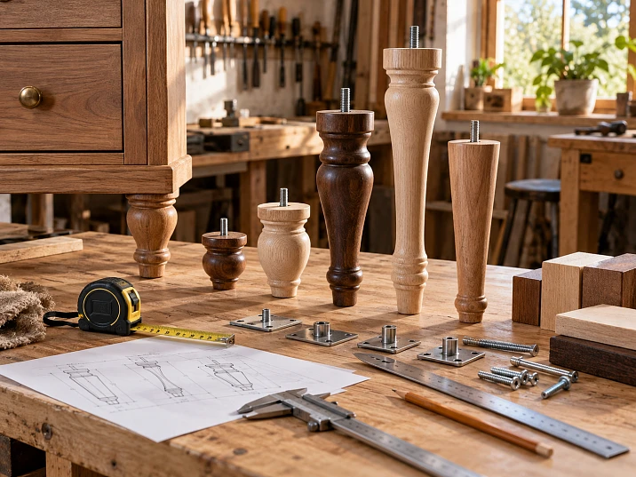
There is enough space under the chest of drawers for four legs, but there is nothing to attach them to yet: the bottom is thin, the corner joints are off to the side, and the chosen mounting plate lands on the lower drawer runner. Visually, the supports fit. To install them, the lower cabinet assembly would have to be changed.
It is useful to do this check before ordering. With a turned wooden support, not only the height and profile pattern matter, but also the top platform, fastener placement, minimum cross-section, and the point where the load is transferred to the cabinet. Even two similar models may require different furniture preparation.
Start with a section of the lower part of the item and a bottom view. On them, you need to link four dimensions: the final height of the furniture, the distance to the mounting plane, the clear space under the cabinet, and the position of the supports on the floor. After that, you can compare specific SKUs and assemble a set.
What furniture data is needed before choosing supports
For a chest of drawers, cabinet, or console, record the dimensions of the body and the estimated weight together with its contents. For a sofa and armchair, the operational load on the seat is also taken into account. An empty frame does not represent all the conditions in which the finished furniture will operate.
Look at which parts of the structure can take the forces from the legs: the bottom frame, corner blocks, side panels, specially provided platforms. The most convenient point on the bottom view is not necessarily suitable for attachment. This is especially noticeable on furniture with a recessed bottom, pull-out drawers, and an open lower tier.
The initial record should include:
- the required final height and minimum clearance from the floor;
- the dimensions and material of the load-bearing part of the body;
- the estimated number of supports and their arrangement;
- load conditions, including asymmetrical filling and use of the furniture;
- the existing attachment, if the supports are being selected as replacements.
If the bottom is not designed for installing legs, the issue is solved by changing the design, not by buying a thicker support. The load path must be clear as a whole: from the body through the mounting assembly and the leg to the floor.




What changes with a turned leg in height
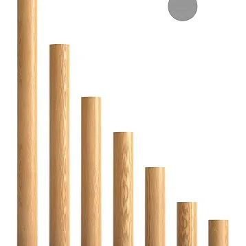
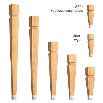
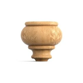
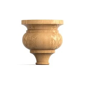
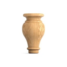
A turned support has a rotational profile: cylindrical sections, cones, necks, rollers, and rounded thickenings may alternate along it. The upper mounting part, however, may have a different shape, including an unturned section for connection to the frame.
Different cross-sections are needed for selection. The maximum diameter shows how much space the widest part will occupy. The minimum helps identify the thin section that must be taken into account when evaluating the structure. The upper cross-section determines possible adjacency to furniture, the lower one — contact with the glide and the floor.
These dimensions do not replace each other. A wide ball in the middle of the leg does not increase the platform at its upper part. A massive base does not eliminate the narrow neck above it. Therefore, the frontal photograph is evaluated together with the dimensional diagram.
In the turned wooden supports first select suitable versions by overall dimensions. Then compare the profile along the entire length and the shape of the mounting part. This order helps exclude options for which an already approved body would have to be redone.
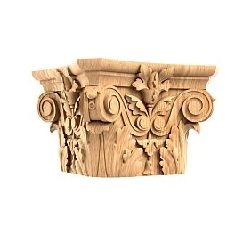
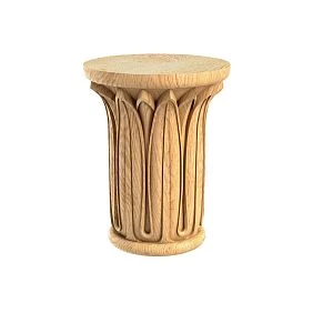
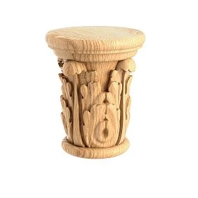
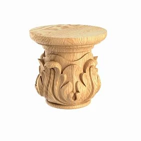
Our factory also produces:
The final height of the furniture is calculated from the selected body plane
To avoid double-counting parts, assign one base plane. For example, the lower surface of the load-bearing frame relative to which the supports will be installed. Measure the body height from this plane to the top point of the finished product, including the top cover, if it is located higher.
The general relationship looks like this:
Furniture height = body height from the base plane + height of this plane above the floor.
The second term consists of the actual vertical height of the support and the dimensions of the mounting unit. Only those layers that actually separate the body and the floor are added. A recessed fit, on the contrary, is taken into account with a minus sign.
Conditional example for direct installation: the mounting plate is located in a recess whose top surface is 18 mm above the base plane of the cabinet. The plate thickness is 5 mm; a support is adjacent to its lower side. This scheme allows the recess depth and the thickness of the connecting part to be accounted for separately.
| Component | Dimension in the example | How it affects the height |
|---|---|---|
| Cabinet from base plane to top | 650 мм | Base cabinet height |
| wooden support | 180 мм | Raises the cabinet |
| Mounting plate thickness | 5 мм | Adds height relative to its installation surface |
| Adjustable foot in working condition | 3 мм | Adds height |
| Depth of the mounting recess above the base plane | 18 мм | Reduces height |
The result is 650 + 180 + 5 + 3 − 18 = 820 mm. All dimensions here are conditional and describe one predefined assembly. For your own project, take them from the drawing and verify them during assembly.
A threaded rod fully inserted into the designated holes does not by itself add its entire length to the furniture height. The mounting plate may also be recessed partially or fully. You cannot simply add up the overall dimensions of all parts from the catalog: you need to calculate the distances between the working surfaces after assembly.
Get Consultation
Why the leg height is not equal to the clearance from the floor
In the example above, the base plane is at a height of 180 + 5 + 3 − 18 = 170 mm from the floor. If the front bottom rail of the cabinet is lowered another 35 mm below this plane, the visible clearance beneath it will be 170 − 35 = 135 mm.
Thus, a 180 mm high support in this design provides a clearance of 135 mm. There is no error in the leg dimensions: part of the height is taken up by the cabinet position and the mounting assembly.
Check the clearance in several places. The front rail may close off the space more than the bottom does, and the center crossbar may sit even lower. For cleaning, what matters is the lowest point along the actual path of the brush or device, as well as the width of the passage between the legs.
If a robot vacuum needs to go under the furniture, use the dimensions of the specific model including protruding parts and clearance requirements. You need a margin for real floor unevenness and installation deviations; it is chosen for your particular case. Matching the device height to the nominal leg height alone is not enough.
On the drawing, it is useful to label the final furniture height and the minimum working clearance separately. Then a change to the cornice, bottom rail, or mounting method will immediately show which of the two parameters no longer matches the task.
How to estimate the diameter without arbitrary coefficients
There is no universal share of furniture width that would determine a suitable leg diameter. An engineering check takes into account the support height, the shape of the transitions, the minimum cross-section, the material properties, the fastening, and the load conditions. A visual check answers a different question: whether the scale of the profile matches the cabinet.
First, rule out the options for which use in your construction is not confirmed. If the product page does not contain data that allows you to assess the load, request it from the manufacturer or provide for calculation and testing of the furniture assembly. You cannot derive the permissible weight of a chest of drawers solely from the maximum diameter of the wooden part.
Then compare the remaining models on the drawing at the same scale. Show the entire cabinet, the plinth area, the fronts, and all four supports. In a separate photo, a leg with a wide collar looks massive; under a large sideboard, the same collar may appear small.
For a compact nightstand or a visually lightweight console, a narrow profile can preserve free space under the cabinet. But a long thin leg requires a separate check of the fastening and lateral rigidity. Visual lightness is not confirmation of permissible load.
Under a wide chest of drawers, a sideboard with a prominent cornice, or a front with a heavy pattern, it is worth comparing more substantial profiles. Check not only the overall diameter: it matters at what height the thickening is located and how much of the support will be visible from under the cabinet.
Two real product codes: what the size tells you and what it does not
In the STAVROS product cards, you can compare, for example, the turned leg MN-145 и MN-194. The tables present the following versions:
| Model | Example of size A × B from the product card | Materials in the size table |
|---|---|---|
| MN-145 | 150 × 44 mm | Beech, oak |
| MN-194 | 150 × 60 mm | Beech, oak |
With the same parameter A, size B differs by 16 mm. For this reason alone, the models need to be repositioned in the bottom view and checked next to the lower part of the cabinet. At the same time, the value B cannot be taken as the diameter of the flat mounting plate or hole without a drawing.
For MN-145, the manufacturer separately states that versions longer than 450 mm are recommended for lightweight wall-mounted consoles and coffee tables. This limitation applies to this model. The presence of a long version in the catalog does not turn it into a universal support for any tall furniture.
Such a comparison provides a list of candidates. The final choice will require information about the top attachment and verification of the entire structure — two dimensions are not enough for this.
Top mounting plate: check the actual contact area
On the upper part of the support, it is necessary to distinguish between the outer contour and the flat surface that will adjoin the mating part. A rounded edge, chamfer, hole, or recess can reduce the available contact area. This is especially noticeable on a turned profile that begins almost immediately below the body.
For the connection, check the width and depth of the upper part or its diameter, the shape of the end face, the position of the hole, and the available depth for the fastener. If the leg is installed through a plate, separately check the contact of the leg with the plate and the fastening of the plate itself to the furniture.
The mounting area of the body must also be suitable. Fastening holes must not accidentally fall on the edge of the board, a void, an old damaged hole, or the runner zone. The required clearances and fastening depth are determined by the hardware and the base material.
A large wooden support does not compensate for a weak section of the body. If the mounting plate turns out to be wider than the available load-bearing zone, its position must be changed, a different connection selected, or the lower frame reworked. Skewing the plate or fastening only the convenient part of the holes is not equivalent to the intended installation.
On finished furniture, measure the assembly after removing the old leg. From an external photo, it is impossible to determine whether there is a captive nut, threaded insert, corner block, or another element inside. Preserving the external height does not guarantee compatibility of the fastenings.
How to check the mounting area in the bottom view
For an initial check, a scaled drawing or full-size paper templates are sufficient. Separately mark the body contour, load-bearing areas, leg axes, contours of mounting parts, and holes. Also indicate internal obstacles: runners, crossbars, fastenings of adjacent assemblies.
The check procedure is as follows:
- Place the support axis relative to the two base edges of the body.
- Overlay the contour of its upper mounting area.
- Add the mounting plate if one is provided.
- Show the location and depth of the mounting holes.
- Check the clearances, tool access, and absence of intersections with other parts.
A conditional example shows why the leg outline alone is not enough. Suppose a round top plate with a diameter of 60 mm is positioned with its axis 35 mm from two outer edges of the cabinet. Its edge is 35 − 30 = 5 mm from each of these edges. This is only a geometric remainder, not confirmation of an acceptable fastening.
If a conditional 90 × 70 mm plate with its center on the leg axis is added to the same joint, its 90 mm side will extend beyond the cabinet boundary by 45 − 35 = 10 mm. The support itself fits in plan, but the plate no longer does. The position or design of the joint will have to be changed.
After checking the contour, measure the hole locations. A plate that fits completely may still have an unsuitable mounting pattern: one screw will hit the edge of the panel, another will land in the empty space next to the side panel. For the final decision, use STAVROS drawings and models and the documentation for the selected hardware.
Straight and angled installation require different checks
With vertical installation, the turning axis coincides with the vertical. With angled installation, the lower point of the support shifts to the side, its vertical projection and the position of contact with the floor change. Therefore, the furniture height and occupied area must be checked again.
The angle cannot be set by simply rotating the leg in the drawing. The connection must ensure the intended joint at the top, and the lower part must provide proper support on the floor. If the end face or the glide is not designed for the selected position, the contact may differ from that of straight installation.
In the STAVROS catalog there is mounting plate FUR-017 with a 10° angleIts product page specifies dimensions of 112 × 70 × 26 mm and a metal M8 threaded insert; fasteners for installing the plate are not included. This is a specific connection part, not permission to tilt any wooden leg.
Check the compatibility of the support model with such an installation, the tilt direction of each leg, and the final position of all supports on the floor. For the pair of front and rear legs, the direction must be fixed on the assembly diagram. Four identical plates may be oriented differently.
The lower part protruding beyond the body also affects furniture use: a person's leg passes nearby, an adjacent object stands there, or a cleaning tool moves past. The maximum product dimension in plan is checked on the assembled structure.
The fastener is selected to match the actual mounting part
For a new design, it is reasonable to first choose a suitable support model, study its upper part, and only then coordinate the hardware. When replacing legs, the existing assembly becomes the initial constraint: the support and a compatible connection will have to be selected simultaneously.
| Fastening element | What it is for | What needs to be matched |
|---|---|---|
| Combination stud | Connects the wooden part and the mating element with metric thread | Both threaded parts, length, installation depth |
| Threaded insert | Creates a threaded socket in the prepared base | Internal thread, outer size, mounting hole and base material |
| Mounting plate | Forms the mounting area and the connection pattern to the body | Dimensions, angle, holes, fastening method |
| Screws and self-tapping screws | Fasten the assembly elements according to the specified pattern | Type, length, diameter and available material thickness |
| Thrust bearing | Provides contact between the lower part of the leg and the floor; in some models allows adjustment | Base size, fastening, added height, purpose |
For example, FUR-001 Kit contains an M8 × 60 metric threaded rod/self-tapping screw and an M8 × 13 metal threaded insert. The identical M8 designation describes the mating metric thread. It does not mean that all pilot holes for these parts must have a diameter of 8 mm.
Drilling diameters, depths and installation method are taken from the instructions for the specific fastener, taking into account the base. The drilling depth cannot be set equal to the full length of the stud: its parts perform different functions and are located in different elements of the joint.
Also check the clearance to the front surface and the internal cavities of the cabinet. When replacing hardware, a longer part may hit the bottom of the hole before the surfaces come together tightly. The absence of a visible gap and the absence of play are checked after correct assembly, without attempting to correct an error by over-tightening.
The suitable one furniture hardware for legs add them to the order as separate line items. Do not assume that the stud, plate, glide foot, and all fasteners are already included in the price of the wooden support.
Four identical supports are a set, but not a ready-made proof of strength
If the project specifies four identical legs, record them as a set of one specification. The item code, size, material, surface preparation, and installation diagram must all match. A model name alone, without the selected size, does not fully define the set.
However, four supports do not necessarily share the load equally. The distribution is affected by the rigidity of the cabinet, the placement of the contents, the position of extended parts, floor unevenness, and assembly accuracy. Simply dividing the total weight of the furniture by four does not replace a structural check.
A wide cabinet may require central support. Its purpose is to participate in load transfer and to limit deformation in the way intended by the design. The number and position of additional supports are determined by the design, not by the external wish to leave only four visible legs under the furniture.
When replacing the supports of a sofa or a long dresser, keep the manufacturer's intended layout until changing it has been verified. Removing an inconspicuous central leg can change how the entire lower frame works, even though the furniture's appearance barely changes.
Stability is considered separately from the strength of an individual part. Raising the cabinet changes the position of its mass relative to the floor. Open drawers also change the weight distribution. If the design includes anchoring the furniture to the wall to prevent tipping, new legs do not remove the need for it.
One sample checks the fit, the full set checks the assembly
For a new item, it is useful to order one support before the main batch. On it, you can measure the mounting part, check the fasteners, evaluate the finish, and perform a trial finish. It is advisable to connect the sample to a fragment of the actual base, not to an arbitrary offcut of another material.
But one leg will not show how four supports work under the cabinet. To check the height of the assembled furniture, the absence of wobbling, the overall scale, and stability, you will need a full trial set and the specified product inspection. An approved appearance does not yet equal an approved design.
In the sample record, separate the results:
- geometry and fit have been checked;
- fastening has been approved for the selected base;
- finish has been approved against the sample;
- the set has been checked on a prototype product.
For evaluating color and texture, the following are available Product samples. They are convenient for a preliminary comparison of wood, but they do not replace the support itself when checking the installation area or the turned profile.
After approval, keep the sample and the inspection date. If the base material, fasteners, or leg height change later, determine which checks need to be repeated. The old approval does not automatically carry over to the modified assembly.
Turned supports for a dresser and a cabinet
For a chest of drawers, first tie the supports to the final height of the top and the position of the upper drawer. If the carcass remains the same, its lift is transferred to all handles and working levels. This is especially noticeable when the chest of drawers must stand next to other furniture at a given height.
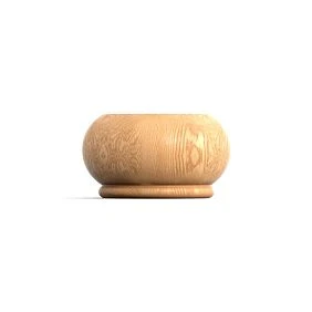
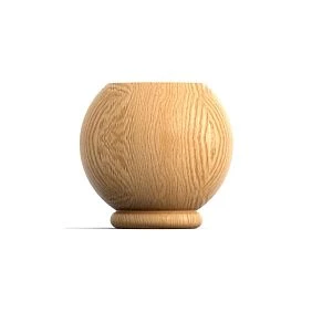
Look at the lower front and the rail — the horizontal part of the frame. They can hide the upper part of the leg and change the visible profile. In the image of the separate support, the expressive bead is well placed, but once installed it almost entirely disappears behind the lower rail. This can be checked on the side section and the full-size template.
For a wide chest of drawers, compare the position of the legs with the vertical dividers and load transfer points. Supports placed at the outermost corners do not necessarily solve the problem of supporting the long bottom between them. If necessary, a lower frame or an additional support is designed.
On a compact cabinet, a scale error is more noticeable. A large base may protrude beyond the carcass, take up passage space, and visually make the cabinet itself look smaller. Recessing the legs too deeply, on the other hand, changes the position of the support points and requires a stability check.
For a bedside cabinet, coordinate the height of the top with the specific bed and the usual way of using it. For a cabinet for equipment, take into account the equipment, cables, and contents. A universal “leg height for a cabinet” does not replace this initial data.
Turned supports for a sofa and an armchair
For upholstered furniture, not only the height of the body is determined, but also the height of the seat. It depends on the position of the frame, the construction of the soft elements, and their deformation when seated. The nominal leg height describes only one part of this chain.
When replacing four identical vertical supports with taller ones, if all other elements and installation conditions remain the same, the rigid frame will rise by the difference in their working heights. But seating comfort is still checked on the assembled furniture. The cushion and the seat tilt contribute to the perception of height.
For a sofa, study the existing corner blocks, central supports, and transformation mechanism elements especially carefully. The new fasteners must not intersect with moving parts. The support is selected for the actual frame load scheme, including use of the seat, and not only by the mass of the empty sofa.
On an armchair, the front and rear supports may perform different tasks and have different geometry. If such a difference is intended by the design, ordering four identical parts will change the position of the seat. First restore the original configuration, then evaluate the permissible replacement.
For furniture with a rocking or reclining mechanism, compatibility of the legs with the existing system must be confirmed separately. An externally suitable turned profile does not indicate whether the required mechanism positions and clearances will be preserved.
For a table, additionally check the apron and legroom
On a table, the upper part of the support interacts with the tabletop and the underframe. Data on the apron, overhangs, joints, and space for a person are needed. The height to the top of the tabletop and the clear distance under the apron are different parameters.
The detailed sequence for this design is covered in the article “Turned legs for a table: how to choose the height, profile, and wooden supports for the tabletop”. To choose a support as a separate component, keep the general principle: match its upper cross-section to the actual joint, and the entire profile to the available space under the furniture.
Beech or oak: choose the material together with the finish
Beech is often considered for furniture intended for enamel finishes, when the legs and the body should receive a single opaque color. Oak is chosen, among other reasons, for its expressive texture under oil, stain, or clear lacquer. These scenarios do not exclude painting oak or applying a clear finish to beech.
The species alone does not make it possible to declare one option structurally better. Two supports with different profiles and fastenings cannot be compared for strength based only on the words “beech” and “oak.” For the selected model, its geometry, the quality of the blank, and the permissible application are taken into account.
In the description quality of solid wood products STAVROS distinguishes between finishes intended for enamel and for tinting. They require different approaches to selecting wood by color and texture. Therefore, in addition to the species, the order must specify the finish intended for the future coating.
If the texture will remain visible, compare the entire set before painting. Four identical item codes from the same species are not required to have an identical grain pattern. Agree on the position of the parts in the finished product and the permissible color variation at the selection stage, especially for a well-lit open furniture base.
Unpainted support or finished coating
Convenient for a workshop with its own finishing from STAVROS open boundless possibilities for designers, furniture makers, and anyone striving to create unique high-quality furniture.. Before applying the coating, dimensions are checked and the specified trial assembly is performed. Then the finishing system is tested on a sample and the set is processed according to the agreed technology.
On a turned profile, color is perceived differently than on a flat board. The raised areas catch the light, the recesses remain in shadow, and different areas of the wood may take stain differently. Evaluate the sample under the lighting that will be present at the furniture, and rotate the support around its axis: the visible side after installation may turn out to be different.
With opaque painting, make sure that preparation and coating layers do not alter the agreed mating surfaces. Threaded elements and technical holes are protected according to the accepted technology. The order of treating joint areas depends on whether contact is required between exposed wood, painted surfaces, or metal hardware.
If you need a fully prepared component, see furniture legs with finish. Check the availability of the specific model, size, and color. The mere existence of a painted category does not mean that any unpainted item is available in the same finish.
Compatible Mounting and finishing materials choose after the joint and finish have been approved. Include the necessary waiting times in the assembly schedule. A surface that is dry to the touch does not always yet allow hardware tightening, packing, or working load.
How to record a turned support in the production specification
The entry "turned leg, oak, four pieces" does not define what exactly needs to be purchased and how to prepare the carcass. The working schedule must link the product card, the assembly drawing, and the approved sample.
Below is the specification form. This is a list of required information, not a ready-made order for a specific model.
| Field | What to record |
|---|---|
| Designation on the drawing | For example, OP-01; the same in all project documents |
| Article number | Full designation from the card of the selected model |
| Dimensional version | All selected dimensions with an explanation of A, B, C according to the diagram |
| Working height of the unit | Distance from the floor to the accepted base plane of the carcass |
| Profile | Maximum overall dimensions, important minimum sections, reference to the drawing |
| Top platform | Shape, contact zone dimensions, holes, and fit |
| Material | Wood species and finish for the agreed coating |
| Mounting | Hardware item codes, layout, depths, and installation direction |
| Thrust bearing | Model, size, working position and added height |
| Finish | Agreed finish type or reference to a finish sample |
| Quantity | 4 pcs. per product, if this exact layout is approved by the project |
| Status | What was checked on the sample and on the assembled product; approval date |
| Product card | Exact page address along with the saved variant parameters |
Hardware is best listed as separate lines. If one mounting kit is required for each of the four legs, then four kits are required for one product. For three identical products, twelve supports and twelve corresponding kits are required. Additional central supports, if provided, are counted separately.
A link to the product page does not replace the size entry. A single page may contain several height variants, different materials, and preparation types. Saved parameters allow you to verify the count and repeat the order without reconstructing the selection from memory.
For a small batch, it is useful to designate the drawing version of the mounting assembly. If the lower frame changes in the next release, the buyer will see that the compatibility of the old support and fasteners needs to be rechecked.
Incoming inspection before assembly
First, the item codes and versions are checked against the bill of materials. Then the set is compared by geometry: the height between identical base surfaces, the top platforms, the position of the holes, and the selected glides. A single method is used for measurements, and the permissible deviations are taken from the agreed requirements.
Check the ends and the areas around the future fastening. A crack near a hole has a different meaning than a shade difference on the visible side. A questionable part should be separated from the kit and agreed with the supplier before drilling, painting, and installation.
Next, assemble a trial assembly with the hardware that will go into production. Check the fit for skewing, the closing of the intended surfaces, and the possibility of tool access. For angled supports, additionally verify the direction of each plate against the drawing.
The finished product is checked on a suitable inspection surface according to the accepted program. If the furniture wobbles, do not start by trimming one leg: the cause may be different glides, incomplete seating of the fasteners, a skewed body, or the floor itself. First determine the source of the difference.
Incoming inspection does not replace testing the furniture for the intended loads. Its task is to prevent a different part or an assembly error from entering an already approved design. For repeatable production, keep the inspection results of the trial set and the agreed inspection method.
What to consider when reordering
A few months later, the same support configuration is needed. A photo of the finished furniture conveys the overall silhouette, but does not show the installation depth of the stud, the dimensions of the mating hole, and the coating composition.
Keep the specification, the assembly drawing, the invoice, and the signed finish sample together. If the supplier offers a substitute item, compare it by height, mounting area, profile, and available hardware. A “similar turned leg” may change the working clearance or require different drilling.
For a series of several items, it is useful to plan purchases in sets. The reserve for a sample, trial finish, or maintenance, if required, is allocated as a separate line with a purpose. There is no universal percentage that suits equally four legs for one chest of drawers and a regular production batch.
Where to buy turned wooden supports
Start the selection with those suitable by design of wooden furniture legs. In the general catalog of solid wood you can coordinate other wooden parts of the project with them, but finalize the choice of support based on its own product page and drawing.
To buy turned furniture legs without re-approval after delivery, provide the supplier with the item code, dimensional version, material, finish requirements, and quantity. If questions about the application remain, attach a bottom view and a section of the assembly indicating the furniture and load conditions. Such a request is more precise than asking to select “four sturdy legs.”
Compare the order cost by the complete set: wooden supports, hardware, glides, specified finish, and delivery. The price of one unpainted part and the price of a component with a coating describe different levels of readiness for assembly.
Workshops should check conditions for manufacturers. Availability and lead time are confirmed for the required sizes, material, and quantity, especially if the order combines several product groups. Payment and shipping terms are given in the section payment and delivery.
Proceed to purchase when the support has been coordinated with the cabinet in three views: front, side, and bottom. The first shows the scale, the second shows the height and clearance, and the third shows the placement of the mounting plate and fastening. Together they provide a sufficiently clear brief for selecting and checking a specific set.
Additional questions
Can a turned support be shortened to the required height?
The possibility of trimming depends on the profile and the design of the ends. At the bottom, the provided seat for the glide can be lost; at the top, the mounting part and fastening depth can be changed. Before processing, check the drawing and confirm that the modification is acceptable. If a suitable size exists in the catalog, choosing it allows the original geometry of the model to be preserved.
Can a load-bearing leg be assembled from separate turned elements?
In the section turned products and construction kit elements parts for composite solutions are presented. However, the availability of elements that can be joined by type does not confirm the load-bearing capacity of the assembled support. Coordinated connections, fixation, load transfer direction, and verification of the entire assembly are required. A decorative module cannot be considered a finished furniture leg based on shape alone.
Will an adjustable glide help if the cabinet is uneven?
It can compensate for a height difference within the specified range if it is compatible with the leg and the load. First, eliminate any skewing of the cabinet and incomplete seating of the supports. Adjustment changes the working height and must maintain acceptable thread engagement; the element must not be unscrewed beyond the permitted position.
Should the same direction of the wood grain be maintained?
For a clear finish, this is a matter of a coordinated appearance for the set. However, with a threaded connection, the position of the support after tightening may not match the desired rotation of the grain. Do not loosen the fastening for the sake of the grain pattern: the ability to orient it must be provided for in the assembly or taken into account when selecting the parts.
Can just one damaged leg be replaced?
Such a replacement can be considered after checking the cause of the damage and the condition of the other assemblies. The new part must match in working height, fit, fastening, and glide. With a clear finish, the appearance is also matched. If the original item code has changed or is unavailable, one similar photo is not enough to confirm compatibility.