Article Contents:
- Why a catalog overall dimension is not enough for a working drawing
- A datum is a clear origin of measurement
- The actual part is measured in its specified position
- The data sheet of a purchased part links the product to installation
- Critical dimensions are determined by the consequences of an error
- The leg is referenced to the mounting plate and the fastening axis
- For a handle, the fastening coordinates are specified on the front
- For a spacer, distinguish contact fit, thickness and thread depth
- The socket is installed from the specified center and direction
- The bracket is anchored to both adjoining surfaces
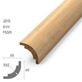
- A specific reference edge is selected on the molding
- The catalog length of the linear stock is transferred to the cutting map
- The dimensional chain is checked between machining and finishing
- After drilling and milling, the part replacement conditions change
- One trial assembly verifies the marking method
- The position must match in the drawing and the specification
- In a series, the datums, orientation, and inspection method are retained
- Where to buy parts for furniture manufacturing with clear project referencing

A handle with an overall length of 160 mm may have a distance between fixings of 128 mm. If the first dimension is transferred to the front instead of the second, the finished part will not fit into the holes. That is why furniture manufacturing parts are linked to the project through mounting surfaces, axes and locating dimensions. Catalogue overall dimensions help to choose a model, but they do not always contain all the information needed for machining the carcass or front.
Before drilling, the workshop needs an unambiguous answer to three questions: which way round the purchased element is installed, from where its position is measured, and what is checked after installation. This information is linked to a specific item code and version so that the designer, purchaser and assembler work with the same part.

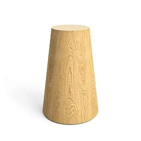
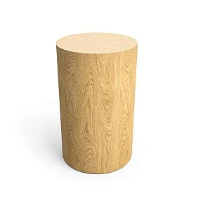
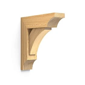
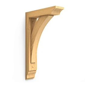
Why a catalogue overall dimension is not enough for a working drawing
The catalogue describes the product: its overall height, width, thickness, length or diameter. A furniture working drawing must additionally show where this part is located relative to the carcass, front and neighbouring elements. Identical overall dimensions of two models do not guarantee identical fixing and arrangement of mounting surfaces.
On a turned leg, the widest section may be below the top platform. On a handle, the overall length includes the decorative ends beyond the fixing points. On an overlay, the most protruding part of the ornament does not coincide with the surface by which it sits against the front. All these dimensions are needed, but they solve different tasks.
Therefore the outer contour, the fit and the position of the fixings are transferred to the project separately. The contour helps to check the adjacency of parts, the fit — the possibility of connection, and the hole coordinates — to carry out machining in the right place. Substituting one group of dimensions for another is discovered too late, when the carcass has already been manufactured.
You can start with drawings and models of STAVROS products. The required document is searched for the selected item code and size. If mounting information is missing, it is clarified or checked on a sample. Dimensions are not reconstructed from a photograph: perspective and image scale do not allow the fit to be determined reliably.




A datum is a clear starting point
In workshop practice, a datum is a chosen surface, line or axis relative to which the position of other elements is specified. For marking out, it is important that the starting point can be determined identically on the drawing, on the actual part and when checking the finished assembly.
For example, for a rectangular front, you can use the face plane, the machined left edge, and the machined top edge. The plane sets the depth position, while the two edges allow you to lay off the hole coordinates. In this case, the drawing must indicate from which side the front is shown.
For a round support, a convenient reference can be the axis of the locating section; for a bracket, it can be the mating surfaces. There is no universal set of rules like "the first datum is always on top, the second is always in the center." The choice depends on how the part connects to the furniture and how it will be held during machining.
Letter designations for overall dimensions in the catalog should not be confused with datum designations on the working drawing. The letter next to a dimension indicates which quantity the product diagram shows; the datum designation indicates the origin of measurement. To pass the task to the craftsman, it is useful to supplement the symbol with a simple explanation: "face plane," "left edge after machining," "axis of the mounting hole."
Our factory also produces:

The actual part is measured in the specified position
Before measuring, verify the item number, size version, material, and surface condition. A sample of a different height or a model with a similar profile does not confirm the mounting dimensions of the selected product. Also check that the drawing being used relates to the same version.
The part is positioned so that the required surface is accessible and no skewing occurs. A flat base is measured along the working areas, not along protruding ornamentation. For a cylindrical fit, the corresponding diameter is checked; for a shaped handle, the distance between arbitrary extreme points is not taken as the center-to-center dimension.
The tool is chosen according to the task. A ruler helps verify the overall dimension, a caliper helps check the accessible cross-section or diameter, and a suitable template helps check a repeated position. But the accuracy of the readings alone does not correct an incorrectly chosen measurement surface. A record with many decimal places may remain useless for installation.
An actual measurement of a single sample does not replace the agreed requirements for a batch. If it disagrees with the documentation, first determine the cause: a different version, an error in the measurement method, or a deviation in the part. Silently changing all the holes in the project to match a single specimen is risky. The record retains the source of the dimension and the condition of the sample on which it was verified.
Get Consultation
The datasheet of a purchased part links the product to installation
A brief card is needed so that installation information does not remain in correspondence or in the designer's memory. It can be kept alongside the specification, but it must indicate both the purchased version and the method of referencing it to the furniture.
| Card field | What to record |
|---|---|
| Position and item number | Designation in the project, supplier item number, selected size |
| Material and condition | Wood species or other material, surface preparation, presence of coating |
| Mounting surface | Where the part contacts the furniture |
| Axes and direction | Reference point for the position, where the top and front side are |
| Dimensions | Dimensions according to the diagram of the specific version |
| Connection | Fasteners, fits, holes and required installation operations |
| Control | Critical dimensions, clearances and assembly condition during inspection |
| Documents | Drawing, its version, data source and approved sample |
For each dimension it is useful to understand its origin: supplier documentation, an agreed workshop drawing or a sample measurement. This shows what has already been confirmed and what still needs clarification before launch.
The data sheet should not promise more than it can deliver. If the back side of the overlay has not been checked for flatness, the entry "flat fit" is not yet confirmed. If the fasteners are sold separately, they are listed as a separate item. These clarifications help avoid a situation where a formally complete order cannot be assembled from the parts actually received.
Critical dimensions are determined by the consequences of an error
A dimension becomes critical when the joint, functionality or agreed position of the furniture depends on it. It is not necessarily the largest one on the drawing. A small hole offset can prevent installation, whereas a noticeable difference in a decorative protrusion is acceptable in a free zone.
| Dimension or characteristic | When special control is required |
|---|---|
| Specified support height | The level of the cabinet or countertop depends on it |
| Hole positions | The fastener must match the purchased part |
| Seating area size | The part must fit into the recess or butt against the base |
| Protrusion from the front | A sash or another part moves nearby |
| Edge and profile cross-section | They are used to assemble the frame or continue the adjacent section |
A reference dimension may mainly be needed to assess proportions, but its role changes with the design. The maximum leg width becomes critical if a rail runs nearby. The decor thickness becomes critical when the clearance is limited.
For important dimensions, specify permissible deviations, the inspection method, and the part condition: before finishing, after finishing, or in the assembled unit. The values are chosen according to the requirements of the specific joint. Assigning the same tolerance to all wooden components just for the sake of table uniformity does not help: different dimensions affect the result differently.
The leg is referenced to the mounting area and the fastening axis
for wooden legs for furniture the upper platform, which connects to the body or mounting plate, often serves as the starting surface. The drawing shows its dimensions, axis position and distances to the edges of the furniture base.
The maximum diameter of the turned profile is specified separately. It is needed to check the outer dimension, but does not automatically determine the area of the upper joint. If the plate is wider than the platform or the fastener falls close to its edge, a beautiful leg silhouette does not solve the connection problem.
The overall height of the furniture is calculated from the installed assembly. The plate, glide and insertion depth are taken into account only to the extent that they actually change the distance from the floor to the body. If part of the fastening is recessed, its full thickness must not be added to the catalogue leg height.
The drawing also indicates the orientation of an angled or directional support. A matching mounting point does not guarantee correct rotation. The required furniture hardware is linked to a specific leg position and its compatibility is checked. After assembly, the position of the body and the operation of the supports are checked together: the dimensions of a single part do not describe the stability of the entire piece of furniture.
For the handle, the coordinates of the mountings on the front are specified
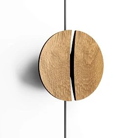
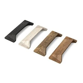
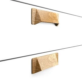
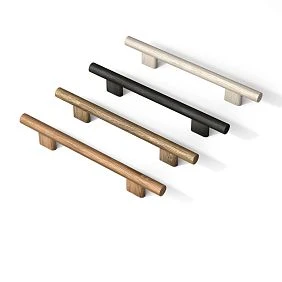
У of a wooden furniture handle the contact surface, number of mounting points, centre-to-centre distance, projection and base size are important. The overall length describes the outer contour. The distance between holes is taken from the installation diagram of the selected version and checked before machining the front.
Example: the width of the finished front is 480 mm. A symmetrical handle is installed in the centre, the distance between its mountings is 128 mm, and the line of holes runs 60 mm from the top edge. In the front view, the front axis is 240 mm from the left edge. The hole centres are located at distances of 176 and 304 mm from it: 240 minus 64 and 240 plus 64.
Both holes receive the same vertical coordinate — 60 mm. The outer length of the handle is not involved in this calculation. It is checked separately together with the grip and possible collisions when opening.
If drilling is performed from the reverse side, the corresponding view is shown on the work order or the reference direction is clearly indicated. For asymmetrical marking, simply turning the front over without changing the reference can produce a mirrored error. The fastener dimensions and its installation depth are agreed with the front thickness and the handle design.
An overlay is characterized by its fit, thickness, and carving depth
for carved furniture overlay the back side facing the front is usually the reference surface. Check which areas actually contact the base and whether their shape allows the chosen mounting method. The relief on the front side does not help determine this from a photograph.
Width and height are compared with the free space inside the frame or between adjacent parts. The position is set relative to the axes and finished edges of the front. For a directional ornament, specify left or right version and orientation. Rotating the part does not necessarily produce the required mirror image.
Overlay thickness and carved ornament depth are different values. If the catalog lists an overall thickness, it cannot be called carving depth. To check clearance, you need the actual protrusion of the installed element relative to the front surface, taking into account the joint design.
The part may fit in width and height but interfere with the adjacent door during movement. Therefore, the protrusion is included in the opening path check. Measuring the free distance only with the furniture closed is not enough. The drawing shows the hazardous adjacency, and a test assembly verifies the required range of motion with the decor installed.
The rosette is installed from the specified center and direction
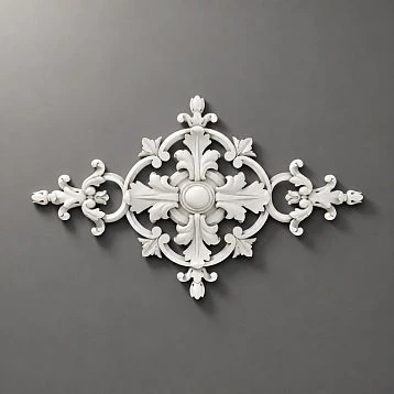
For the central wooden rosette on the front, first set two intersecting installation lines. Their position is measured from the selected edges or other agreed datums. Then the center of the part indicated on its diagram is aligned to the intersection point.
A random petal edge is inconvenient for repeatable marking. On another size or a similar ornament, it may be located differently relative to the center. If the product is asymmetrical, the project separately defines the accepted installation center and pattern direction. The geometric center of the overall rectangle does not always coincide with the desired visual position.
A template with marked axes and clear orientation is used for repetition. Its task is to transfer the approved position onto the facade. The template must not allow the part to be silently rotated or its top and bottom swapped if this changes the pattern.
If the rosette covers the joint of the moldings, not only the center but also the overlap area is checked. Its base must conceal the intended ends of the profiles. With this installation, the position of the rosette is tied to the frame layout, so both parts of the project are checked together. Thickness and fit are considered separately so that the decorative center does not become a source of loose installation.
The bracket is tied to both adjoining surfaces
wooden bracket it often connects to a vertical surface and a horizontal part located above. The project requires their relative position, the size of the contact areas, the projection, and the fastening points. The height of the item alone does not show how it will fit into this corner.
The drawing determines which surface sets the main position and which one is used to check the second junction. If the assembly assumes a right angle, the actual part and the furniture are checked for compliance with this condition. A mismatch must not be corrected by forced tightening in the hope that the ornament will hide the gap.
Two mating surfaces are not always enough to uniquely position the element along the shelf. Therefore, a lateral coordinate or placement axis is additionally specified. It allows the offsets of several brackets to be repeated and linked to the overall furniture composition.
The purpose is specified separately: decorative finishing or participation in supporting the upper part. For load-bearing use, the item, fasteners, and base are assessed together; a massive appearance does not confirm the permissible load. Before processing, access for tools and the installation sequence are checked. A fastening point may be correct in coordinates but inaccessible after the adjacent panel is installed.
a specific reference edge is selected for the molding
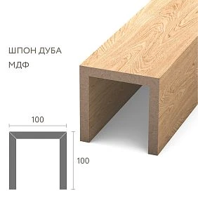
for wooden furniture moulding the mounting plane and the line along which the profile is placed are specified: the outer edge, the inner edge, or a designated center line. The selected reference is used on all corresponding facades.
Conditional example: the facade measures 500 × 700 mm, and the outer edge of the frame is 40 mm from each edge. The outer size of the frame is 420 × 620 mm. If the profile takes up 20 mm inward on each side, the free field is 380 × 580 mm.
In this diagram, the inner edge is located 60 mm from the edge of the front. If the assembler takes the 40 mm dimension as the offset to the inner edge, a different frame will result. That is why the drawing shows which specific line the dimension refers to, rather than limiting itself to the label "moulding offset."
An asymmetric profile is additionally oriented: where its outer and inner sides are, and which section faces the central field. Matching strip width does not prevent a reversal error. The projection above the front is checked separately from the width, especially near an overlay, handle, or moving door.
The catalog length of the linear stock is converted into a cutting map
The length of the purchased strip shows what material will arrive at the workshop. To manufacture the frame, the lengths of specific segments, the profile direction, and the shape of their ends are needed. This information is recorded in the cutting map along with the quantity.
For the flat rectangular frame considered, with an identical profile 20 mm wide and a 45-degree joint, the segment dimensions will differ on the outer and inner sides:
| Segment | By the outer vertices of the cuts | By the inner vertices of the cuts |
|---|---|---|
| Upper | 420 мм | 380 мм |
| Lower | 420 мм | 380 мм |
| Left | 620 мм | 580 мм |
| Right | 620 мм | 580 мм |
The selected method of specifying the length, with a clear depiction of the cut, is passed to production. The two values in the table explain the difference in measurement but do not replace the processing diagram. For a different joint or an inclined profile position, the calculation will be different.
When distributing segments across purchased strips, the saw kerf, the required end preparation, and possible pattern matching are taken into account. The total length of the sides is not yet a finished cutting map. If front sizes vary within a series, each group is assigned its own map while maintaining a common reference system.
The dimension chain is checked between processing and finishing
In a finished assembly, several dimensions work together. The position of the handle depends on the hole coordinates and the dimensions of the front, the height of the cabinet depends on the support and the fastening, and the free field of the frame depends on its outer position and the profile width. What is checked is the resulting outcome, not just each number individually.
For repeated holes, it is convenient to set the position from common agreed datums. Sequential marking "from the previous hole" can carry an error further along the row. At the same time, contradictory duplicate dimensions are avoided on the drawing: the operator must understand which values define the machining and which serve as a check.
Particular attention is paid to the condition of the edge. If the design offset is specified from the finished faced side, but marking is performed on the blank before facing, the difference between these surfaces must be taken into account. Trimming after drilling also changes the distance from the hole to the new edge.
The coating is considered where it affects the fit and the protrusion. A tight recess, threads and precise joints require coordinated preparation. The material, surface condition and finishing requirements are clarified in the description product quality and according to the selected coating system. A universal paint thickness is not substituted into the calculation: the required result is verified using the specified technology.
After drilling and milling, the conditions for replacing the part change
Before machining begins, the position of the element exists in the documentation and marking. After drilling, it is fixed by the holes; after milling, by the groove, recess or machined contour. The new model must correspond to the geometry already produced, or it will require a predefined rework.
For a handle, this limitation is the hole centers and the footprint of the base. For a leg, it is the location of the plate, insert or other fastening. For a decorative element installed in a recess, the contour, depth and position of the mounting surface are important. A part that matches in overall dimensions does not necessarily conform to these limitations.
Before machining the first production batch, the article number, dimensional version and drawing version are approved. This is not a prohibition on further changes, but a clear boundary: after it, any change is verified taking into account the operations already performed.
If a replacement arises, the affected datums, holes, fits and clearances are reviewed. A similar appearance does not allow the previous marking to be retained automatically. At the same time, there is no need to redesign unaffected furniture: the specific changed assembly and its connections to adjacent parts are recorded. The decision is made before continuing drilling or milling, so that mixed variants do not appear unnoticed within the same batch.
A single trial joint verifies the marking method
A full-size printout helps assess scale, axes and composition. Before use, its size is checked against a control segment: print settings can change the scale imperceptibly. But a flat template does not show the seating depth, the handle overhang or the actual fit of the bracket.
A physical sample is needed for a mounting check. The availability of a suitable option can be confirmed in the section product samples; a material sample does not replace the part being installed. Verifying a connection often requires a full product in the selected version.
The trial joint is made with the essential parameters that will be used in the series: base thickness, fasteners, seating treatment and surface condition. It is used to check not only that the holes align, but also whether the part can be held, the tool can be brought in, and installation can be performed in the required sequence.
After fitting, the control dimensions and the movement of adjacent elements are assessed. If an error is found, the drawing or marking method is corrected, then the affected operation is checked again. A successful result is recorded before the remaining parts are processed. For load-bearing joints, such a fitting confirms mounting compatibility, while strength and stability are checked as part of the intended furniture structure.
The position must match in the drawing and the specification
The specification states what to buy, and the drawing states where and how to install it. A single position creates the link between them: for example, "ОП-01" for a support or "РУ-01" for a handle. These are internal workshop designations that do not replace the supplier's item number.
A single position is assigned a specific version with dimensions, material, surface condition and quantity. The drawing shows its location, datums and mounting parameters. If identical items are installed in different places, the quantity and the individual references required for installation are noted.
| Where the information is located | What question does it answer |
|---|---|
| Specification | What to order and in what quantity |
| Purchased part card | Which characteristics and connections are confirmed |
| Assembly drawing | Where to place the part and where to measure dimensions from |
| Operation work card | How to orient the workpiece, secure it, and verify machining |
When a position changes, linked documents are updated. It is not enough to correct the item number in the purchasing list if the old holes remain on the drawing. It is also not enough to change the drawing while leaving the old model in the supplier order. The working set indicates the current version and date, and previous versions are kept separately from the documents used for production.
In a series, the bases, orientation, and inspection method are retained
An approved trial assembly does not by itself ensure repeatability. The craftsman must reproduce the same reference surfaces, workpiece position and fixture settings. For a jig or template, specify which stop rests against the edge and where the face side is located.
Left and right parts must be distinguished with particular care. Flipping the template to the opposite side may require a mirrored arrangement, or it may keep the same reference — the design determines this. The answer must be found in the work order, not decided from memory while drilling.
After setup, the first machined part is checked. Repeat inspection is needed after changing the setup, replacing the template, tool or base version, if this affects the result. A properly functioning jig allows both a correct and an incorrect coordinate to be repeated quickly, so its actual performance on the workpiece is verified.
When receiving the next batch of purchased components, the assembly-relevant parameters are checked in an agreed order. Datum references must not be transferred independently from a similar model. If the part number changes, it is first checked against the existing assembly, then the documents are updated and, if necessary, a trial assembly is performed. This preserves the link between the selected part, the machined front and the method of inspecting the finished furniture.
Where to buy parts for furniture making with a clear link to the project
Select ready-made wooden furniture parts At STAVROS it is convenient to search by the function of the future assembly: support, handle, overlay, socket, bracket or profile. After choosing a model, the dimensional version, material and installation information needed for your own drawing are specified.
For a specific request to the supplier, provide the part number, required dimensions, quantity and questions about the mating surfaces. If a particular contact area or hole position matters, it is useful to mark it on the drawing. A request for "the same size" does not show which parameter determines compatibility.
Workshops with repeat orders should check conditions for manufacturers, and coordinate receipt of the sample and the batch taking into account payment and delivery. The work plan includes time for fitting and approving the assembly before drilling holes and making cutouts in the series.
Furniture manufacturing parts become part of the working project when their mating surface, axes, critical dimensions, and post-assembly inspection are defined. Then a purchased component can be correctly positioned, verified, and reordered, while drilling and milling are performed according to unambiguous data tied to the actual product.